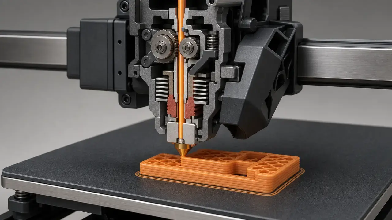

Summary: FDM Printing Guide
This FDM printing guide explains how filament-based 3D printing works, which settings change which outcomes, how common material families differ, and when filament printing is a better fit than resin printing for a given job. [5] [22]
The most useful way to think about fused deposition modeling is as a chain of linked decisions rather than a search for universal “best settings.” Filament is fed, melted, deposited as a bead, cooled, and bonded to previous roads, so visible results such as layer lines, warping, support scars, and directional strength follow from both process physics and setup choices. [5] That is why this guide treats layer height, nozzle diameter, line width, speed, temperature, cooling, walls, infill, and supports as interacting variables; compares PLA, PETG, ABS, ASA, TPU, nylon, PC, soluble supports, and filled composites as families rather than single magic numbers; and frames FDM vs SLA as a requirements decision about geometry, finish, workflow, and material behavior. [2] [13] [18] [22]
Terminology: Material Extrusion, FFF, and “FDM”
In standards language, the formal process category is material extrusion, not “FDM” or “FFF.” Standard-based: ISO/ASTM 52900:2021 is Edition 2, published in 2021-11, listed by ISO as 28 pages, and confirmed in 2025, making it the current vocabulary anchor for additive manufacturing terminology. [1] For this article, the standards-derived definition to use is: “an additive manufacturing process in which material is selectively dispensed through a nozzle or orifice.” [4] In everyday maker use, FFF usually means filament-based material extrusion, but the process family is broader than any one consumer label or printer brand. [1] [4]
NIST draws the same boundary: its polymer additive manufacturing report describes material extrusion as selectively dispensing a thermoplastic polymer through a nozzle, and notes that Stratasys trademarked FDM® for its systems that use this technique. [5] That matters because “FDM” is common shorthand in hobby, education, and engineering conversations, while material extrusion is the formal category name used in standards and metrology contexts. [5] Stratasys also states that “Fused Deposition Modeling” and “FDM” are trademarks, so the careful wording is that FDM is a common-use term that roughly maps to filament-based material extrusion or FFF in consumer practice, without implying that ordinary generic usage is actively policed in everyday discussion. [9]
Key terms in one glance
| Term | Plain-language meaning | Scope note |
|---|---|---|
| Material extrusion | Formal AM process category where material is dispensed through a nozzle or orifice. [1] [4] | Standards term; broader than consumer brand labels. [1] |
| FFF | Common consumer name for filament-based material extrusion. [4] [5] | Common-use label, not the formal ISO/ASTM process family name. [1] |
| FDM | Common shorthand for filament printing, but also a Stratasys trademark. [5] [9] | Best treated as a common term in use, with trademark awareness. [9] |
| Vat photopolymerization | AM family that cures liquid resin with light. [22] | Parent category for SLA, DLP, and MSLA/LCD. [22] |
| SLA | Laser-based vat photopolymerization. [22] | Use when laser scanning matters to the point being made. [22] |
| DLP | Projector-based vat photopolymerization. [22] | Whole image exposure per layer rather than point scanning. [22] |
| MSLA/LCD | Masked vat photopolymerization using an LCD-style mask. [22] | Common in consumer resin printers. [22] |
| Accuracy | Closeness of the printed geometry to the target geometry. [3] | Not the same as repeatability. [3] |
| Precision | Consistency across repeated prints or measurements. [3] | A print can be precise but inaccurate. [3] |
| Resolution | A partial descriptor of feature capability, not a full quality score. [3] [18] | Needs process-specific context to be meaningful. [3] |
Historical snapshot
The core FDM patent record shows a filing and priority date of 1989-10-30 and a publication date of 1992-06-09. [7] A Stratasys SEC filing says the company was incorporated in 1989 and “sold our first commercial product” in April 1992. [8] That is the clearest historical anchor: late-1980s invention and patenting, followed by an early-1990s commercial launch, rather than broad claims that desktop-style filament printing was already widely commercial earlier than the cited record supports. [7] [8]
Technical principles of fused deposition modeling technology
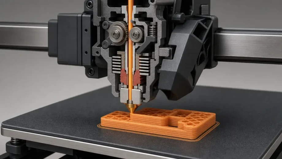
Fused deposition modeling technology works by pushing solid thermoplastic filament from a spool, or from a drybox when moisture control matters, through an extruder drive into a heated hotend. The hotend melts the filament, the nozzle meters the flow, and the motion system places the molten bead on the bed or on the previous layer. NIST describes the process as melting filament, extruding material through a nozzle, and placing the bead onto the substrate, with successive beads layered to create the final three-dimensional structure. [5]
The most important physics happens after the bead leaves the nozzle. The new road is hotter than the material it touches, so heat flows into the previous bead or layer and allows polymer diffusion across the interface. NIST describes the resulting fusion as dependent on temperature gradient, polymer structure, and bead geometry, which is why identical slicer settings can behave differently across materials and hotends. [5] As the roads cool, they contract, which can leave residual stress. If neighboring lines do not merge well enough, small voids remain between beads. If the thermal history changes too quickly, interlayer bonding can weaken. Because the part is built from aligned roads stacked in layers, NIST also describes material-extrusion parts as highly anisotropic, with anisotropy that can vary non-linearly with processing parameters. [5]
Those mechanics also show up visually. Layer lines reflect the deposited bead stack. Support marks show where extra material touched the part. Warping reflects uneven contraction and restraint. Small gaps or weak seams often point to poor bead fusion or moisture-related extrusion problems. Even surface quality is partly a map of bead placement, cooling, and geometry rather than a single printer trait. [5]
Core elements of an FDM printer
- Spool or drybox: stores feedstock and, for hygroscopic filaments, helps control moisture exposure. [14]
- Extruder drive: grips and pushes filament at a controlled rate into the hotend. [5]
- Hotend and nozzle: melt the polymer and meter the bead size at deposition. [5]
- Heated bed: improves first-layer adhesion and reduces thermal shock. [13]
- Motion system: places the nozzle or bed to build the toolpath in layers. [5]
- Part cooling: changes overhang behavior, bridging, and thermal history between layers. [5]
- Slicer and G-code: convert geometry and process settings into machine instructions. [23]
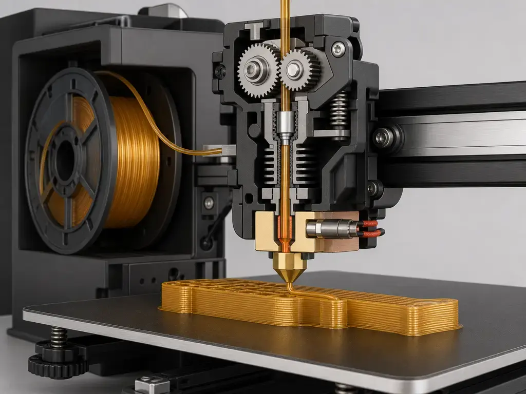
Fused deposition modeling process: from CAD model to printed part
The fused deposition modeling process starts well before plastic leaves the nozzle. In a software-agnostic workflow, you model or import the geometry, orient it on the build plane, assign print settings, generate the additive toolpath, preview the result, and post-process the toolpath into a G-code print file for the machine. [23] Autodesk’s FFF workflow description is useful here not because it is brand-specific, but because it captures the generic sequence most slicers follow: orientation, print settings, slicing, simulation or preview, then machine-ready output. [23]
Typical FDM workflow
- Create or import the CAD model and check that it is manifold and printable. [23]
- Choose a material family and hardware setup that match the part’s use case. [23]
- Orient the part for support strategy, visible surfaces, and expected load direction. [23]
- Apply a validated print profile, then adjust key slicing settings only where needed. [23]
- Generate supports, brims, or rafts when geometry or warping risk requires them. [23]
- Slice and preview the toolpath, layer sequence, walls, infill, and support interfaces, then export G-code. [23]
- Print, inspect, post-process, and measure the part against the design intent. [23]
Orientation, support generation, and profile choice determine many outcomes before printing begins. A vertical hole may print very differently from a horizontal one. A cosmetic face placed on support will usually need more cleanup than the same face angled or reoriented. A part with a small first-layer footprint may need a brim or redesign even if the upper geometry seems simple. Good FDM practice is therefore front-loaded: use the preview to inspect walls, thin sections, unsupported spans, contact patches, and toolpath intent before committing time and material to the build. [23]
Printer architectures and how they change print outcomes
Printer architecture matters because it changes how the same material and toolpath are physically executed. Cartesian, CoreXY, and delta systems can all produce good parts, but they do not excite vibration in the same way and they do not carry the same moving mass. The practical consequence is simple: a motion system that rings or overshoots at the chosen acceleration and pathing will leave ghosting or waviness on surfaces even if extrusion settings are correct. Direct-drive and Bowden extrusion paths matter for a different reason: the filament path changes how quickly the machine can start and stop flow, so flexible materials such as TPU usually benefit from tighter filament control and gentler pressure dynamics than a long, springier path provides.
Enclosures and heated chambers change thermal stability, not just appearance. A warmer, more stable environment generally helps warp-prone materials such as ABS, ASA, nylon, and PC by slowing uneven cooling across the part. That is different from air-quality control: an enclosure can reduce drafts and improve thermal consistency, but it is not automatically fume extraction. Multi-material machines, soluble-support setups, and toolchangers widen what geometry is practical, but they also add purge behavior, idle-tool management, and more opportunities for support workflow to dominate total job time rather than printing alone. [20] [21] [24]
FDM printer settings that matter (and how they interact)
There are no universal best FDM printer settings because the result depends on material, nozzle, hotend throughput, geometry, environment, and the part objective. The same machine may want one setup for a quick enclosure bracket, another for a clean PLA demo model, and a third for a nylon functional part. The useful mindset is to treat settings as coupled controls on bead geometry and thermal history, not as isolated menu items. [5] [11] [25]
Settings at a glance
| Setting group | What it mainly changes | Useful boundary or example | What goes wrong when pushed too far |
|---|---|---|---|
| Layer height | Vertical step size, print time, stair-stepping, and interlayer contact area. | Vendor example: Prusa recommends keeping layer height below 80% of nozzle diameter; with a 0.4 mm nozzle that is about 0.32 mm maximum. [11] | Poor layer bonding, rough topography, or unstable extrusion if the bead is too tall for the nozzle size. [11] |
| Nozzle diameter and line width | Practical bead size, minimum external detail, and throughput. | Vendor example: Prusa offers common 0.25 / 0.4 / 0.6 mm nozzle presets, and hardened nozzles are recommended for abrasive filaments. [26] | Fine details vanish, corners soften, or print time balloons if hardware and line strategy do not match the job. [26] |
| Nozzle-specific layer capability | Realistic layer-height window for a given nozzle on a real machine. | Vendor example: one UltiMaker manual lists a 0.4 mm nozzle at 20–200 µm layer resolution. [31] | Treating a minimum layer figure as a universal quality guarantee. [31] |
| Temperature, speed, and throughput | Melt quality, flow consistency, bonding, and print time. | Vendor example: Prusa defines maximum volumetric speed as the maximum plastic throughput, in mm³/s, that the hotend can reliably melt. [25] | Under-extrusion, weak seams, gloss changes, or missed steps when commanded speed exceeds melt capacity. [25] |
| Cooling, walls, infill, and supports | Overhang behavior, shell stiffness, internal weight, and cleanup workload. | More cooling usually helps bridges and overhangs, while stronger shells usually come from wall strategy before infill percentage changes. [5] [10] [12] | Brittleness between layers, sagging bridges, weak edges, or heavy post-processing scars. [5] |
Layer height, nozzle diameter, and line width are closely linked. Smaller nozzles can place finer beads, but that does not automatically make every part more accurate; it mainly changes the practical bead scale and the number of roads needed to build geometry. Larger nozzles can raise throughput and build thicker walls quickly, but they also change the minimum practical feature size and corner behavior. The vendor rule of thumb to keep layer height below 80% of nozzle diameter is useful because it ties a slicer input to a hardware limit instead of a vague quality idea. [11] The separate UltiMaker example of 20–200 µm for a 0.4 mm nozzle shows why “minimum layer height” and “good layer-height range” are different questions. [31]
Speed numbers by themselves are incomplete. If you double print speed without considering line width and layer height, you are not just asking the machine to move faster; you are asking the hotend to melt and push more plastic per second. That is why volumetric flow limits matter. Vendor example: Prusa describes maximum volumetric speed as the maximum plastic throughput, in mm³/s, that the hotend can reliably melt, making it a practical speed limiter even if the motion system could move faster on paper. [25] Temperature and cooling sit in the same loop. More nozzle temperature can support higher throughput or better fusion, but too much heat can soften detail, worsen stringing, or overcook some polymers. More part cooling can improve bridges and overhangs, but because FDM bonding depends on thermal history at the bead interface, heavy cooling can also reduce interlayer fusion in some cases. [5]
Walls, infill, supports, adhesion aids, retraction, and flow are also coupled. If you need better screw-hole durability or stiffer edges, additional walls often do more than simply increasing infill density. If the part only fails at the first layer, a brim or better bed preparation can matter more than changing the entire profile. Retraction can reduce stringing, but very aggressive retraction is not free: it can increase grind, clogging tendency, or inconsistency, especially with soft or moisture-affected filaments. Supports are not just a yes-or-no setting; support density, interface layers, and contact placement trade cleanup effort against geometric freedom. [10] [12] [14]
Settings interaction matrix
- Faster print speed usually requires either more melt capacity, more temperature, less flow demand, or some combination of the three; otherwise the hotend reaches its volumetric limit and under-extrusion appears. [25]
- A larger nozzle enables thicker lines and often higher throughput, but it also changes fine-detail capability and edge definition. [26] [31]
- More cooling can improve bridges and overhangs, but too much cooling can reduce layer-to-layer fusion because bonding depends on thermal gradients and interface diffusion. [5]
- Fewer walls cannot always be “replaced” by more infill when edge stiffness, threads, screw bosses, or sealing faces matter. [10] [12]
- Retraction that is acceptable for PLA can behave poorly with TPU, wet nylon, or long filament paths because extrusion pressure control changes with material and path compliance. [14] [29]
FDM materials comparison (families, not single numbers)
A useful FDM materials comparison starts with the standards view that material-extrusion plastics include unfilled, filled, and reinforced materials and can also contain additives such as flame retardants or stabilizers. [2] That is why talking about “PLA” or “nylon” as if each were one fixed substance is misleading. In practice, what matters is material family, formulation, colorant, reinforcement, moisture state, and the printer’s ability to process that combination. The numbers below are therefore vendor examples or standards framing, not universal truths for every spool carrying the same family name. [2]
Materials comparison table
| Family | Good for | Vendor example or standards anchor | Main constraints |
|---|---|---|---|
| PLA | Easy printing, concept models, classroom use, visual prototypes. | Vendor example: Prusament PLA lists 210 ± 10 °C nozzle, 40–60 °C bed, 100% fan, and 55 °C heat resistance on its page and TDS-style material information. [27] | Low heat resistance by engineering standards; can deform in warm environments; grade-specific behavior varies. [27] |
| PETG | Tougher general-purpose parts, enclosures, functional prototypes, moderate chemical exposure. | Vendor example: Prusa lists 215–270 °C nozzle and 70–90 °C bed for PETG. [13] | Can string, can weld strongly to some surfaces, and benefits from controlled cooling rather than maximum fan. [13] |
| ABS | Tougher functional parts and post-processed parts. | Vendor example: Prusa lists 230–255 °C nozzle and 95–110 °C bed for ABS. [13] | Warp-prone, usually benefits from an enclosure, and surface quality drops quickly in drafty thermal conditions. [13] |
| ASA | Outdoor-capable parts and ABS-like use cases where UV and weather resistance matters. | Vendor example: Prusa lists 220–275 °C nozzle and 90–110 °C bed for ASA. [13] | Still sensitive to thermal management; do not assume one ASA grade behaves like another from a different supplier. [13] |
| TPU | Flexible grips, tires, bumpers, cable protection, compliant parts. | Vendor example: Prusament TPU 95A lists Shore 95A, 230 ± 10 °C nozzle, 65 ± 10 °C bed, and 78.6 °C at 1.80 MPa HDT. [29] | Soft filaments are path-sensitive, slower to print, and can still absorb enough moisture to affect quality. [14] [29] |
| PA / nylon | Tough wear parts, clips, low-friction parts, mechanically demanding prototypes. | Vendor example: Prusa lists 240–285 °C nozzle and 70–115 °C bed for PA; UltiMaker’s Nylon TDS says printed-part properties vary with orientation and that Z-direction interlayer strength is typically the lowest in FFF. [13] [19] | Hygroscopic, often needs drying and dry storage; wet nylon can bubble, string, and lose print quality. [14] [19] |
| PC | Higher-temperature engineering parts, brackets, machine-adjacent components. | Vendor example: Prusament PC Blend lists 275 ± 10 °C nozzle, 110 ± 10 °C bed, 20% fan, and temperature resistance up to 113 °C. [28] | Demands more heat and adhesion control than beginner materials; enclosure or skirt can help stability. [28] |
| Soluble supports | Internal channels, trapped geometry, cleaner support interfaces in dual-material workflows. | Vendor example: PVA dissolves in water and attracts moisture; HIPS requires D-limonene; industrial Stratasys FDM soluble supports dissolve in a very mild NaOH solution and depend on model-support pairings. [20] [21] [30] | Dissolution chemistry, compatibility, storage, and post-processing time differ by support system; “soluble” does not mean interchangeable. [20] [21] [30] |
| Filled composites | Stiffer feel, lower warping in some cases, dimensional stability, or aesthetic surface effects. | Standard-based: filled and reinforced feedstocks are part of the material-extrusion scope. [2] Vendor example: carbon, glass, and Kevlar-filled filaments are highly abrasive, and Prusa notes some CF-filled filaments are mainly aesthetic rather than structural upgrades. [15] [26] | Abrasive wear on nozzles; hardened nozzles recommended; filled is not the same as continuous-fiber reinforcement. Continuous-fiber figures are not covered here, and no reliable figure was found for a universal strength multiplier. [15] [26] |
PLA, PETG, ABS, and ASA are often treated as a simple ladder from beginner to engineering materials, but application fit matters more than ranking. PLA is easy to process and good for concept work, yet its vendor example heat resistance of 55 °C shows why it is a poor default for hot-car interiors or parts near warm electronics. [27] PETG often sits in the middle ground with better toughness and chemical resistance than PLA, while ABS and ASA move further toward heat-capable functional work at the cost of tighter thermal management. [13] ASA is especially worth separating from ABS when outdoor exposure matters, but neither family should be reduced to a single temperature number because brand, pigment, and modifier package all change behavior. [13]
TPU, nylon, and PC widen the use-case envelope, but they also expose setup weaknesses quickly. TPU prints are sensitive to the extrusion path and pressure control. Nylon brings toughness and useful wear behavior, yet it is one of the clearest examples of why moisture handling matters: Prusa flags polyamide as strongly affected by humidity, and UltiMaker’s Nylon TDS explicitly reminds readers that printed-part properties vary with orientation and that interlayer strength in the Z direction is typically the weakest in FFF. [14] [19] PC raises temperature capability further, but the vendor example of 275 ± 10 °C nozzle and 110 ± 10 °C bed should be read as a reminder that the printer must be up to the job, not as a generic command for every PC spool. [28]
Support materials and filled composites add workflow constraints that beginners often underestimate. Water-soluble PVA is attractive because it can free trapped geometry and improve underside finish, but it is moisture-sensitive and still requires a planned workflow. [20] HIPS is not just another version of PVA, because the dissolution route is different: UltiMaker’s materials guide says PVA dissolves in water while HIPS requires D-limonene. [30] Industrial soluble supports differ again; Stratasys describes FDM soluble supports that dissolve in a very mild NaOH solution and are paired with specific model-material families rather than treated as universal. [21] Filled composites also need precise language: a chopped-fiber-filled PLA or nylon may improve stiffness or appearance, but it is not the same as a continuous-fiber composite system. [2] [15]
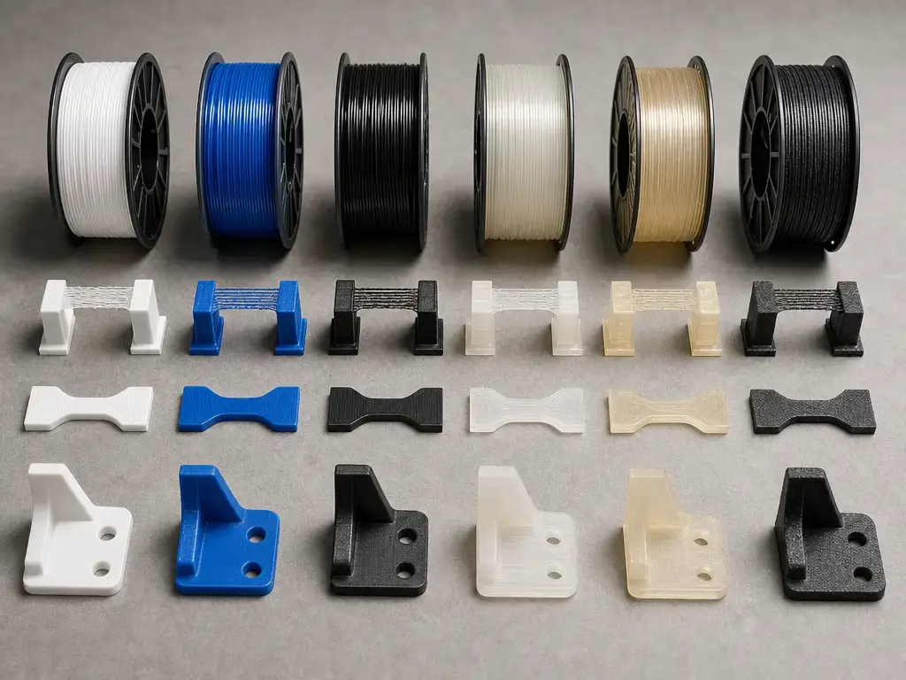
Design constraints vs slicer fixes (what geometry makes hard)
Many printing problems that look like bad settings are actually geometry problems. Overhangs, bridges, thin walls, holes, clearances, and warp-prone footprints all ask the process to do something specific with a bead of molten polymer and a cooling schedule. Vendor example: one Stratasys Direct guide recommends a minimum wall thickness generally around 4× slice thickness, which is a useful service-provider reminder that wall design and layer strategy are linked rather than independent. [10] Xometry likewise treats walls, holes, and clearances as design-for-process questions, not just slicer toggles. [12]
Geometry limit vs tuning lever
| Geometry risk | Symptom | Best geometry fix | Settings-only mitigations |
|---|---|---|---|
| Overhangs and bridges | Sagging undersides, curling edges, messy undersurfaces. | Reorient, split the part, add self-supporting angles, or redesign unsupported spans. [10] [12] | More cooling, lower layer height, slower bridging, and supports can help, but they do not erase a poor geometry choice. [5] [12] |
| Holes | Undersized or slightly non-round holes. | Model for drilling or reaming when holes are critical, and orient holes strategically. [10] [12] | Lower layers and tuned perimeters can improve shape, but tuning alone rarely makes every hole exact. [12] |
| Thin walls | Missing walls, weak skins, or slicer dropouts. | Make walls intentional multiples of expected line width; for service-specific context, Stratasys Direct ties wall minimums to slice thickness. [10] | Smaller nozzles or single-wall strategies may help, but if the wall is below practical bead logic, redesign is better. [10] [12] |
| Clearances and moving parts | Fused joints or parts that break free poorly. | Design explicit clearance and orient contact surfaces to reduce welding risk. [12] | Elephant-foot compensation and support tuning help at the margins, not as a substitute for clearance design. [12] |
| Warp-prone shapes | Corner lift, split seams, internal stress. | Round corners, reduce large flat spans, add ribs, or split the part into lower-stress modules. [10] [12] | Enclosure, brim, adhesion prep, and cooling changes help, but geometry can still dominate the outcome. [10] [24] |
Industrial and service-provider examples are useful here only when labeled as examples. Vendor example: one Stratasys Direct guide lists build volume up to 36 × 24 × 36 in (914 × 610 × 914 mm) and layer thicknesses of 0.005–0.020 in (0.127–0.508 mm), which shows that industrial FDM can span much larger envelopes and coarser-to-finer production modes than a typical desktop setup, but those numbers are not universal process limits. [10] The main lesson is not to memorize a single wall or hole rule. It is to separate what can be tuned from what should be redesigned. [10] [12]
FDM vs SLA printing: choosing the right tool
The clean comparison is not “filament good, resin bad” or the reverse. It is FDM vs SLA printing as a fit-to-requirements choice inside a wider AM landscape. FDM, or more formally filament-based material extrusion, is usually the easier route for durable, quick-turn functional parts, larger prototypes, shop fixtures, and lower-mess handling of materials in solid form. [5] [22] Vat photopolymerization, which includes SLA, DLP, and MSLA/LCD variants, usually has the advantage when the part requires finer visual detail, smoother surfaces straight off the machine, or delicate geometry that would telegraph bead structure too strongly in FDM. [18] [22] The key wording is that vat-photopolymerized parts often do not have the same bead-to-bead interfaces as FDM parts, but orientation and post-cure still affect properties, so isotropy should be treated as application- and material-dependent rather than assumed as an absolute. [18] [22] Independent study support for that qualified view comes from Ait Mou and Koc, who compared FDM, SLA, and material jetting and found smoother SLA surfaces while also reporting distortion of thin features below 1 mm in their studied setup. [18]
FDM vs vat photopolymerization at a glance
| Criterion | FDM / filament-based material extrusion | Vat photopolymerization | Practical takeaway |
|---|---|---|---|
| Material state | Solid thermoplastic filament. [5] | Liquid photopolymer resin cured by light. [22] | Handling, storage, and cleanup are fundamentally different. [22] |
| Typical visible finish | Vendor example: FDM commonly shows more visible layer texture. [22] | Independent study and vendor guidance both point to smoother surfaces as the common trend. [18] [22] | If finish is the first priority, resin often starts ahead. [18] [22] |
| Layer-height marketing range | Vendor example: UltiMaker lists FDM typical layer heights around 50–400 µm. [22] | Vendor example: the same comparison lists SLA typical layer heights around 25–100 µm. [22] | Useful as broad guidance only, not a guarantee of part quality. [22] |
| Orientation sensitivity / interface behavior | Built from deposited roads with bead interfaces and strong process anisotropy concerns. [5] | Often lacks the same bead-interface structure, but orientation and post-cure still matter. [18] [22] | Do not reduce either process to a single isotropic or anisotropic label without context. [18] |
| Supports and post-processing | Manual support removal, or soluble support workflows if hardware allows. [20] [21] | Washing and usually post-curing are part of the normal workflow. [22] | Workflow time can outweigh print time in both cases. [20] [21] [22] |
The workflow difference is often more important than spec-sheet comparisons. Standard single-material FDM usually ends with support removal and perhaps trimming or sanding. Resin usually adds washing and a post-cure step. Dual-material FDM can also become chemistry-dependent: PVA dissolves in water, HIPS requires D-limonene, and industrial soluble support systems may rely on mild alkaline baths and material-specific pairings. [20] [21] [30] The better question is not which process is better, but which process creates the needed geometry, finish, mechanical behavior, and shop workflow with the least compromise. [18] [22]
Performance metrics: accuracy, precision, resolution, tolerance, surface finish
The fastest way to misunderstand 3D printing is to trust one marketing “resolution” number as if it summarizes the whole machine. It does not. Resolution can refer to layer height, display pixel pitch, laser spot size, practical line width, or minimum feature capability depending on the process. Standard-based: ISO/ASTM 52902:2023 is about geometric capability assessment through benchmarking artefacts and measurement, serving capability evaluation and calibration, and it explicitly does not prescribe a specific procedure or machine settings for making the test piece. [3] That is the right frame for engineers: capability is something you measure on parts, not something you infer from one brochure number. [3] The independent FDM-vs-SLA capability paper reinforces the point by separating dimensional process capability from surface roughness rather than treating them as the same outcome. [18]
Metrics & what they really mean
| Term | What it is | How it’s measured or observed | Common mistake |
|---|---|---|---|
| Accuracy | Closeness of the printed feature to its nominal CAD target. [3] | Measure artefact features and compare to nominal dimensions. [3] | Confusing it with repeatability or smoothness. [3] |
| Precision / repeatability | How consistently the printer reproduces the same result. [3] | Repeat builds or repeated measurements and compare spread. [3] | Assuming a single good part proves repeatability. [3] |
| Tolerance | The allowable dimensional band required by the application. | Defined by design intent, then verified by inspection. [3] | Treating a printer ad claim as a guaranteed part tolerance. |
| Resolution | A partial descriptor of the smallest addressable step or feature, depending on process. [3] [18] | Process-specific observation of thin walls, edges, steps, pixels, or bead placement. [3] | Using one resolution number as an overall quality score. [18] |
| Layer height | The Z-step between deposited layers. | Slicer setting plus visible stair-stepping on sloped faces. [11] [31] | Treating it as the whole story for detail or accuracy. [18] |
| Nozzle diameter | Physical outlet size that constrains practical bead scale. | Hardware specification and print planning. [26] | Assuming a smaller nozzle automatically makes all features accurate. |
| Line width | The actual width of an extruded road in the toolpath. | Preview or measure printed walls and top surfaces. | Assuming it must always equal nozzle diameter. |
| Surface finish | The texture or roughness left on the part surface. | Visual comparison, touch, or formal roughness measurement. [18] | Treating smooth finish as proof of dimensional accuracy. [18] |
ISO/ASTM 52902 matters because it shifts the conversation from slogans to evidence. Instead of asking whether a printer is high resolution, you ask what artefact you printed, what features you measured, what uncertainty the measurement carried, and whether the result was repeatable enough for the job. [3] That mindset also prevents false certainty around hobby heuristics. Vendor example: Prusa’s rule to keep layer height below 80% of nozzle diameter is useful hardware guidance, but it is not an all-purpose accuracy metric. [11] Vendor example: the UltiMaker 0.4 mm nozzle range of 20–200 µm is a machine-specific capability window, not a guarantee that any geometry printed at 20 µm becomes better in every dimension. [31]
A smaller nozzle, thinner layers, and careful line-width planning can improve external detail and edge fidelity on the right part. They still do not collapse the whole quality question into one number. The better discipline is to inspect relevant features such as holes, thin walls, steps, bosses, mating faces, and repeated builds, then decide whether the printer, profile, and material combination actually meets the needed capability. [3] [18]
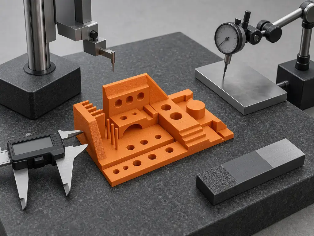
Strength & durability: why orientation, walls, and moisture matter
Raw polymer properties are not the same as printed-part properties. A filament datasheet may describe the bulk material, but a printed FDM part is a road-and-interface structure whose strength depends on how well those roads fused, how many voids remain, how the bead geometry was laid out, and what direction the load takes through the part. NIST’s description is explicit: part strength comes from both the deposited material and the interface between beads, with fusion depending on temperature gradient, polymer structure, and bead geometry. [5] That is why wall count, contour direction, and build orientation can matter as much as the family name on the spool. More infill does not always rescue a weak shell, and a strong bulk polymer can still produce a disappointing part if interlayer bonding was poor. [5] [10]
For test context, ASTM D638-style tensile specimens are a common reference in the literature, but the useful point is not to memorize a tensile number. It is to remember that independent studies measure printed parts under controlled specimen geometry and process conditions because the process itself changes the outcome. Tymrak et al. provide an open-access mechanical study in that ASTM D638 context and are a useful reminder that results depend on print method and conditions, not just material label. [16] The independent ASA FFF study makes the design implication even clearer by concluding that build orientation, infill angle, and void fraction strongly influence tensile strength and elongation. [17]
Moisture adds another variable that directly changes durability and consistency. Prusa warns that most FFF materials are hygroscopic and that polyamide is affected especially strongly; the same guide connects wet filament with poor surface quality, stringing, low layer adhesion, blobs, bubbling, and even smoke during extrusion. [14] UltiMaker’s Nylon TDS adds the orientation reminder that printed-part properties vary with build direction and that Z-direction interlayer strength is typically the lowest in FFF. [19] In practice, dry filament improves not only cosmetic output but also the mechanical trustworthiness of the finished part. [14] [19]
Limitations, failure modes, and safety (including emissions)
FDM is versatile, but it is not geometry-agnostic and it is not failure-proof. Common problems come from the same process features that make it accessible: a bead can sag if it lacks support, shrink if it cools unevenly, absorb moisture before printing, or fail to merge properly if the thermal window is wrong. Many visible issues are diagnostic rather than random. A clean failure-analysis mindset is more useful than swapping profiles blindly. [5] [14]
Common FDM failure modes to explain
- First-layer adhesion loss.
- Warping and corner lift.
- Stringing and oozing.
- Under-extrusion or intermittent flow.
- Layer separation or weak Z bonding.
- Bridging sag and overhang collapse.
- Support-interface scars.
- Moisture-driven bubbling, blobs, rough surfaces, and poor layer adhesion. [14]
Safety is practical. Hotends, nozzles, beds, and moving axes can burn or pinch. Filled filaments are abrasive in the machine, and sanding or cutting composite-filled parts can create unpleasant particulate dust during post-processing, so treat cleanup as a real shop step rather than an afterthought. [15] Emissions also need careful language. The desktop-printer emissions study cited here found very different indoor outcomes between a large, well-ventilated office and a small, unventilated room, with detectable ultrafine aerosol and VOC effects in the poorer-ventilated case. [24] The conservative takeaway is simple: ventilate the room, be cautious with material-specific odors and emissions, and do not assume an enclosure equals extraction. An enclosure can improve thermal stability and help with warp control, but it is not the same as capturing and removing airborne contaminants. [24]
Applications of FDM printing (and when not to use it)
FDM is a strong fit for functional prototypes, jigs and fixtures, electronics enclosures, teaching models, cosplay parts, workshop adapters, low-volume tooling aids, and many iterative design tasks where speed, low material-handling complexity, and broad thermoplastic choice matter more than mirror-smooth finish. It is especially useful when you want to test form and assembly quickly, tune a design through several versions, or print larger parts without the workflow of liquid resin handling.
It is a weaker fit when the part demands extremely fine visual detail with minimal visible layering, when very small unsupported features dominate the geometry, or when the application requires validated performance beyond what an informal shop process can prove. Food-contact parts, safety-critical components, medical use, and other critical end-use applications require validation; a material name on a spool does not by itself make the finished part certified, compliant, or safe for that use.
Current research directions (no market trend claims)
Current research in material extrusion is still centered on measurement and control rather than simple consumer-facing feature claims. NIST’s material extrusion research page highlights polymer additive manufacturing and rheology work, including measurement of temperature and stress fields and real-time material responses in polymeric materials. [6] That emphasis makes sense because bead formation, cooling, and bonding are fundamentally thermo-rheological problems before they become slicer presets. [5] [6]
Metrology remains equally important. Standard-based: ISO/ASTM 52902 frames capability assessment around printed artefacts, measured features, and calibration use cases, which is the kind of groundwork needed for better process qualification, closed-loop monitoring, and comparison across machines and materials. [3] The same direction also supports work on high-performance polymers and filled or reinforced feedstocks, because new material options are only useful when flow behavior, dimensional capability, and repeatability can be characterized credibly. [2] [3]
Practical takeaways for an FDM printing guide
Use this FDM printing guide as a workflow rule set: start with a validated profile, focus on the first layer, change one variable at a time, choose material by use case, and compare FDM vs SLA by requirements instead of chasing one-number claims.
FAQ
Here are short answers to the most common follow-up questions.
What is the fused deposition modeling process?
It is a material-extrusion workflow in which thermoplastic filament is fed into a hotend, melted, extruded through a nozzle, deposited in roads and layers, then cooled into a finished part according to a sliced toolpath and G-code instructions. [5] [23]
What is the difference between FDM and FFF (and where does “material extrusion” fit)?
Material extrusion is the formal standards category. FFF is a common-use name for filament-based material extrusion. FDM is also widely used in common speech, but NIST notes that Stratasys trademarked FDM for its systems, and Stratasys states that “Fused Deposition Modeling” and “FDM” are trademarks. [4] [5] [9]
What are the best FDM printer settings?
There are no universal best settings. Start with a validated profile for your printer and material, then tune toward the part objective. Vendor example: layer height should stay below 80% of nozzle diameter, and speed should respect the hotend’s maximum volumetric throughput rather than just a headline mm/s value. [11] [25]
Does nozzle size affect accuracy, resolution, or just detail?
Nozzle size affects practical bead scale, line width, throughput, and minimum external detail more directly than it affects accuracy by itself. Vendor examples such as 0.25 / 0.4 / 0.6 mm nozzle presets and a 0.4 mm nozzle layer range of 20–200 µm show that nozzle choice changes the process window, but measured dimensional capability still has to be verified on real parts. [26] [31] [3]
Why do FDM prints warp, and what fixes are geometry vs settings?
Warping is driven by uneven cooling and contraction, so geometry matters first: large flat footprints, sharp corners, and stress-concentrating shapes are harder than compact or rounded parts. Settings can help with enclosures, bed adhesion, cooling control, and brims, but they do not fully cancel a warp-prone design. [10] [12] [24]
How can I evaluate dimensional accuracy and repeatability instead of trusting “resolution” specs?
Print a relevant test artefact, measure critical features, repeat the build, and compare the results to the nominal CAD model and to each other. That is the capability mindset reflected by ISO/ASTM 52902: use artefacts and measurement for assessment and calibration, instead of assuming one advertised resolution number predicts real part performance. [3] [18]
Sources
- ISO/ASTM 52900:2021 listing (vocabulary) — Standard listing (ISO) — 2021-11, confirmed 2025. https://www.iso.org/standard/74514.html
- ISO/ASTM 52903-1:2020 listing (feedstock scope) — Standard listing (ISO) — 2020-04. https://www.iso.org/standard/67290.html
- ISO/ASTM 52902:2023 listing (test artefacts/geometric capability) — Standard listing (ISO) — 2023-08. https://www.iso.org/standard/79683.html?browse=tc
- NIST-hosted standards slide deck (process category definitions including material extrusion) — Standards slide deck — references ASTM F2792-08 wording. https://www.nist.gov/document/plenarystuckerpdf
- NIST IR 8059 PDF (mechanism, anisotropy, FDM trademark note) — Government report — 2015. https://nvlpubs.nist.gov/nistpubs/ir/2015/NIST.IR.8059.pdf
- NIST “Material Extrusion” technology page — Government web page — updated 2025-05-15. https://www.nist.gov/additive-manufacturing/research-areas/technologies/material-extrusion
- US Patent record (Crump FDM patent timeline) — Patent record — filed 1989-10-30; published 1992-06-09. https://patents.google.com/patent/US5121329A/ja
- Stratasys SEC filing (incorporation and April 1992 first product sale) — SEC filing — published 2011. https://www.sec.gov/Archives/edgar/data/915735/000120677411000449/stratasys_10k.htm
- Stratasys trademark language (FDM / Fused Deposition Modeling as trademarks) — Manufacturer document — 2014. https://www.stratasys.com/contentassets/45c6576621134316a2efb29a1920f235/wp_fdm_enduseparts_en_1114_web.pdf?v=48fd38
- Stratasys Direct FDM Design Guide — Manufacturer/service design guide — year not stated. https://www.stratasys.com/siteassets/sdm/content—website-storage/design-guides/dg_sdm_fdm_0725a.pdf?v=490918
- Prusa: Layers & Perimeters — Manufacturer help article. https://help.prusa3d.com/article/layers-and-perimeters_1748?product=cw1
- Xometry FDM mini-guide — Service provider guide. https://www.xometry.com/resources/3d-printing/mini-guide-fdm-3d-printing/
- Prusa: Filament material guide — Manufacturer help article. https://help.prusa3d.com/filament-material-guide
- Prusa: Drying filament — Manufacturer help article. https://help.prusa3d.com/article/drying-filament_332086?product=mk3s
- Prusa: Composite materials (filled with carbon, kevlar, or glass) — Manufacturer help article. https://help.prusa3d.com/article/composite-materials-filled-with-carbon-kevlar-or-glass_167387?product=mk3-5
- Tymrak et al. (2014) independent mechanical study — Peer-reviewed paper — 2014. https://wiki.re3d.org/images/d/da/Mechanical_Properties_of_Components_Fabricated_with_Open-Source_3-D_Printers.pdf
- FFF ASA orientation/infill-angle tensile study — Peer-reviewed paper — 2022. https://www.sciencedirect.com/science/article/pii/S2213846322001018
- Comparative dimensional/surface capability paper (FDM vs SLA vs material jetting) — Peer-reviewed paper — 2019. https://pdfs.semanticscholar.org/dde7/b2d259742e95208c7ce205c877fcdf9fa283.pdf
- UltiMaker Nylon TDS — Manufacturer TDS — 2022-04-20. https://um-support-files.ultimaker.com/materials/2.85mm/tds/NYLON/Ultimaker-Nylon-TDS-v5.00.pdf
- UltiMaker: support materials beginner guide — Manufacturer educational article. https://ultimaker.com/learn/support-materials-a-beginners-guide/
- Stratasys: FDM Support Materials — Manufacturer support documentation. https://support.stratasys.com/en/Materials/FDM/FDM-Support-Materials
- Vendor comparisons for FDM vs SLA — Manufacturer educational pages. https://ultimaker.com/learn/fdm-vs-sla-printing-comparing-3d-printing-technologies/ ; https://formlabs.com/blog/fdm-vs-sla-compare-types-of-3d-printers/
- Autodesk Fusion FFF tutorial — Official documentation. https://help.autodesk.com/cloudhelp/ENU/Fusion-CAM/files/MFG-TUT-ADDITIVE-FFF.htm
- Characterization of emissions from a desktop 3D printer and indoor air measurements in office settings — Peer-reviewed study record — 2015/2016. https://pubmed.ncbi.nlm.nih.gov/26550911/
- Prusa: Max volumetric speed — Manufacturer help article. https://help.prusa3d.com/article/max-volumetric-speed_127176?product=mk3
- Prusa: E3D V6 Nozzles — Manufacturer help article. https://help.prusa3d.com/article/e3d-v6-nozzles_920168
- Prusament PLA — Manufacturer material page. https://prusament.com/materials/pla/
- Prusament PC Blend — Manufacturer material page. https://prusament.com/materials/prusament-pc-blend/
- Prusament TPU 95A — Manufacturer material page. https://prusament.com/materials/prusament-tpu-95a/
- UltiMaker: What materials can be used for 3D printing? — Manufacturer educational article. https://ultimaker.com/learn/what-materials-can-be-used-for-3d-printing/
- Ultimaker 2+ User manual — Manufacturer manual — 2019. https://um-support-files.ultimaker.com/manuals/user-manual/UM2%2B/Ultimaker%202%2B%20User%20manual%20EN%20v2.0-2019.pdf