
Summary
3d print speed is a target setting, not a guarantee of how fast a printer actually moves or how quickly a part finishes. [2] In practice, speed sits inside a multivariable process: temperature, layer thickness, extrusion limits, motion settings, and material behavior interact, so faster settings can improve throughput without predicting print quality on their own. [6] This article treats speed as process-specific, especially for material extrusion and resin systems, and focuses on how settings, hardware limits, and part geometry shape the result. [1] [9]
Why There Is No Single Speed Number
There is no single 3d print speed number because additive manufacturing does not use one shared throughput metric across all processes. ISO/ASTM 52900:2021 is the terminology anchor for this language, and it helps keep process families distinct when discussing speed. [1] In practice, a useful setting on one machine can be irrelevant on another because the limiting factor may be motion, extrusion, thermal behavior, or curing rather than the same nominal mm/s value. [2] [6]
That becomes even clearer across process categories. In laser powder bed fusion, the variable set includes powder layer thickness, hatch distance, scan speed, and laser power, so the speed question is already defined differently from desktop filament printing. [12] Resin systems often express output as build rate or layer-based throughput, while material extrusion commonly uses linear motion speed plus extrusion throughput. [9] [10] A 3d print speed comparison only makes sense after the process and units are matched, so FFF-style mm/s should not be treated as equivalent to resin mm/h. [1] [9]
What 3D Print Speed Means
In 3d print speed, “speed” usually means a commanded process setting rather than a universal machine property. In standards-based additive manufacturing language, that distinction matters because material extrusion is a specific process category, not just a generic label for every desktop printer. [1] In practical use, print speed is one control among several that shape throughput, surface quality, and reliability. [2] [6]
The slicer or machine interface typically separates several related controls:
- print speed
- travel speed
- acceleration
- jerk / junction handling
- max volumetric flow
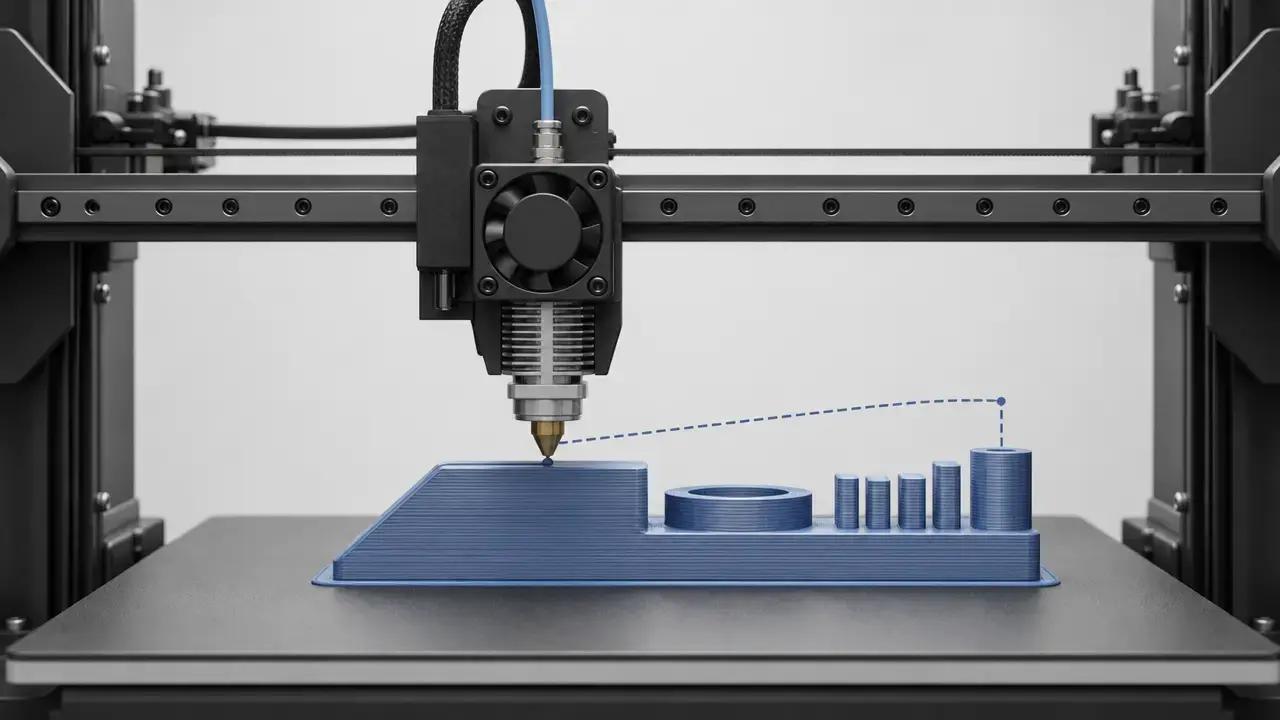
These settings do different jobs. A printer may be told to move at a certain print speed, but the motion planner can still limit the achieved motion because of short segments, cornering, acceleration limits, or extrusion constraints. [2] Prusa’s documentation explicitly notes that print speed is a target, not a guarantee, and that small parts may never reach the commanded value. [2] Older and current documentation also keeps print speed separate from travel speed: the Ultimaker 2 manual lists print speed at 30 to 300 mm/s and travel speed at 30 to 350 mm/s. [7]
Motion-compensation features such as input shaping can help a machine stay cleaner at higher travel speeds and accelerations, but they are compensation methods, not speed numbers. [5] NIST metrology work makes the same broader point by varying extruder temperature, extruder speed, and printed layer thickness together rather than treating speed as an isolated knob. [6] In other words, print speed settings only make sense as part of a linked process.
Definition box
Commanded print speed is the slicer or firmware target for depositing material. [2]
Actual achieved speed is the motion the printer really reaches after acceleration, segment length, and planning limits are applied. [2]
Throughput or max volumetric flow is the material delivery ceiling that can cap real output even when higher motion speeds are commanded. [3]
Print Speed vs Layer Height
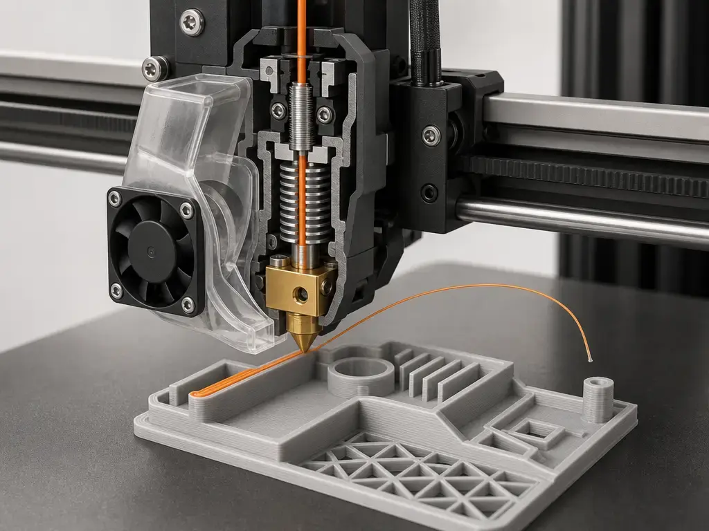
Print speed vs layer height is not a simple one-for-one tradeoff, but layer height does change the total number of layers. Thicker layers can therefore shorten a job even when the motion-speed setting stays the same. [6] In material extrusion, though, that only helps if the rest of the system can keep up. Layer thickness has to be considered alongside nozzle temperature, extrusion rate, and machine behavior rather than in isolation. [6]
Several limits can flatten the time savings. Line width, nozzle diameter, hotend melt capacity, cooling, and minimum layer time all affect whether a thicker layer can be printed reliably. [3] A practical example from Prusa is that a 0.8 mm nozzle with a 0.5 mm layer height can run into volumetric limits, which means the printer may no longer sustain the intended throughput even if the speed setting looks high. [3] In resin printing, Formlabs lists layer heights ranging from 25 to 200 µm, which shows that layer-based timing also exists outside filament systems, though the units and constraints are different. [10]
How Print Speed Settings Work in Slicers
If you want to know how to change 3d print speed settings, start with feature-based controls rather than a single master slider. Slicers typically expose separate values for walls, infill, top surfaces, first layers, and travel moves because different parts of the print have different quality and reliability priorities. [2] A printer profile therefore acts more like a set of linked limits than one speed number. [2]
The split is practical. Outer walls usually need better surface quality and dimensional consistency than infill, while travel moves are non-printing motion and can often be optimized differently. [4] Legacy official documentation also distinguishes print speed from travel speed with separate ranges, reinforcing that they are not the same control. [7]
Higher acceleration and jerk-related settings can reduce elapsed time, but they also affect quality. UltiMaker notes that increasing jerk can speed prints while lowering print quality, and that pushing acceleration too far can produce ringing. [8] Compensation features such as input shaping may let supported machines run higher travel speeds and accelerations with less ghosting, but they are still not substitutes for feature-level tuning. [5] The practical takeaway is that slicer speed controls work best when adjusted by feature and by limitation, not as one global answer. [2]
What Is a Good 3D Print Speed?
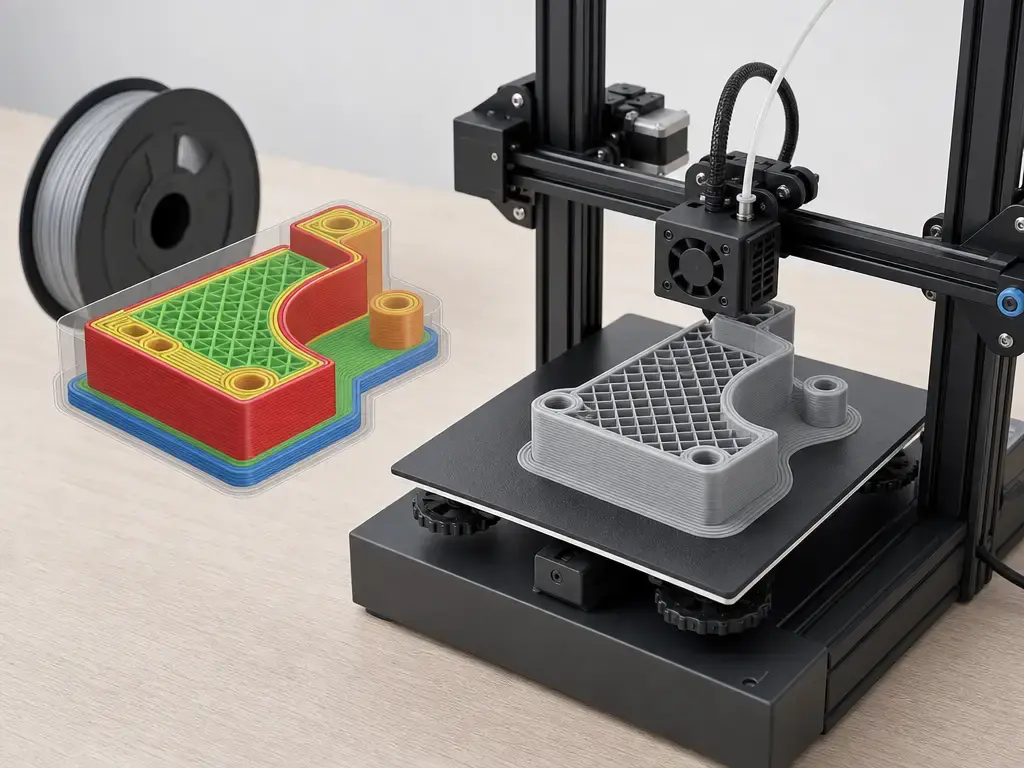
There is no reliable universal mm/s figure for what is a good 3D print speed. [2] [7] The workable range depends on the printer, material, nozzle, geometry, and motion limits. Even one machine can have a wide documented range: the Ultimaker 2 manual lists print speed at 30 to 300 mm/s and travel speed at 30 to 350 mm/s. [7] In practice, the commanded setting is only a starting point, and small parts may never reach it. [2]
A practical way to choose settings is to start from the vendor profile for your printer, material, and nozzle, then validate with a calibration part and change one variable at a time. [2] That matters because motion settings can trade speed for quality. UltiMaker notes that higher jerk can reduce quality and that high acceleration can cause ringing. [8] Manufacturer speed examples can also depend on tightly defined conditions: Bambu’s ASA Aero technical data sheet lists test specimens printed at 100 mm/s with a 225 °C nozzle, an 85 °C bed, and 100% infill, which is a test condition rather than a universal setting. [13]
How to Increase 3D Print Speed Without Losing Too Much Quality
How to increase 3d print speed without losing too much quality starts with separating motion and extrusion tuning from total print-time reduction. Raising a motion setpoint, raising usable flow, reducing layer count, and reducing support material are related ideas, but they are not the same lever. [2] [3] [12] One change may stress the printer, while another simply reduces the amount of material or path length the machine has to produce. [3] [8]
A safe approach is incremental: make one change, inspect the result, and only then proceed. [2] This matters because vendor examples often reflect narrow test conditions rather than general use. The Bambu ASA Aero example is one such case, and UltiMaker’s guidance also warns that aggressive motion settings can reduce quality. [13] [8]
- Start from a validated profile. [2]
- Increase infill speed before wall speed. [4]
- Use larger layer heights only where geometry allows. [3] [10]
- Verify hotend and flow ceiling before raising line throughput. [3]
- Review travel moves and supports. [2] [8]
- Test acceleration or input shaping only if the machine supports it. [5] [8]
If you are trying to shorten print time, keep motion and extrusion tuning separate from geometry changes. Faster infill, revised travel behavior, or higher usable flow can save time without changing the visible surface much, while changing orientation or reducing supports can cut time more dramatically but may also change finish, strength, or post-processing needs. [8] That is why support reduction and speed changes should not be treated as the same lever. [8]
A Compact Comparison of Common Speed Controls
The most useful 3d print speed comparison inside a slicer is not one number but a set of controls. Prusa’s documentation distinguishes print moves from travel moves, and its pressure equalizer explanation reflects the common pattern of slower perimeters and faster infill. [2] [4]
| Setting | What it controls | Typical reason to lower it | Typical reason to raise it |
|---|---|---|---|
| outer wall | visible perimeter quality | better surface finish and dimensional consistency | faster perimeter time |
| inner wall | internal shell speed | improve stability on thin features | reduce print time |
| infill | internal structure speed | reduce vibration or flow stress | shorten elapsed time |
| top/bottom | skin and closure layers | improve top surface or sealing | reduce time on low-visibility areas |
| first layer | bed adhesion and start-up behavior | improve adhesion and reliability | rarely raised unless well characterized |
| travel | non-print moves between features | reduce oozing or mechanical disturbance | cut dead time between segments |
In practice, outer wall and first layer are usually protected first when quality matters, while infill and some travel behavior are often the first places users look for time savings. [2] [4]
FFF, SLA, and Why Speed Numbers Don’t Translate
FFF and other material-extrusion workflows commonly use mm/s motion framing plus volumetric flow, while SLA or MSLA workflows commonly use build-rate framing such as mm/h. [1] [3] [9] These are different measurement systems. Formlabs lists Form 4 maximum print speed at 100 mm/h, a typical average of 40 mm/h, and a material-dependent typical range of 16 to 50 mm/h. [9] The same company also lists resin layer heights from 25 to 200 µm in its adaptive layer thickness discussion. [10]
A second resin example shows the same process-specific variation. Formlabs’ Form 4B dental support page lists application examples ranging from about 8.2 to 90.0 mm/h depending on material, layer thickness, layout, and job height. [11] Industrial additive manufacturing uses another variable set again. In the NIST LPBF publication, energy density is described through laser power, scan speed, powder layer thickness, and hatch distance. [12] So no direct 3d print speed comparison should treat FFF mm/s and resin mm/h as if they measured the same thing. [1] [9]
Limits, Failure Modes, and When Slower Is Better
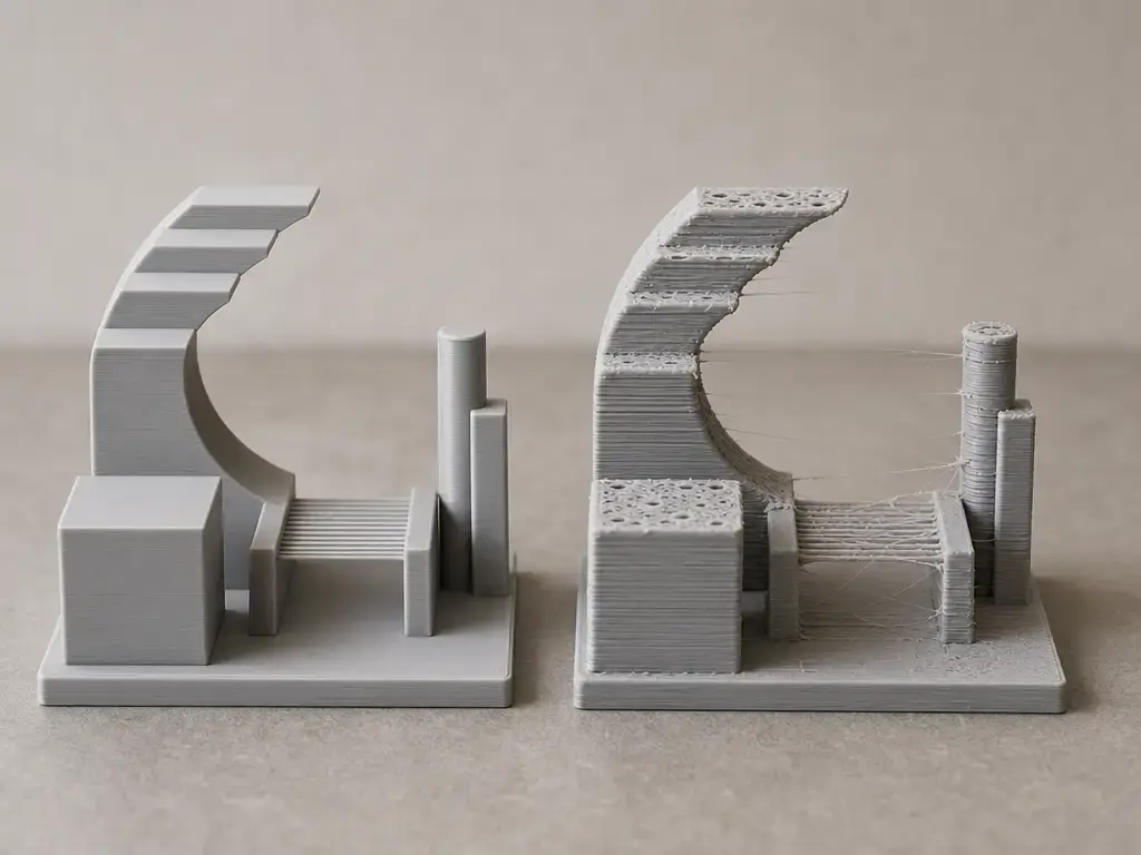
Faster settings can expose limits in motion and extrusion, but the result is usually a quality shift rather than one clean failure mode. UltiMaker notes that high acceleration can cause ringing and that higher jerk can speed prints while lowering quality. [8] In practice, that can appear as ringing or ghosting on walls, rough corners, stringing during fast travel behavior, or overhang quality loss when cooling and deposition can no longer keep up. [6] [8]
Slower is often the cleaner fix when the problem is localized. Under-extrusion may come from exceeding flow capacity, weak layer bonding may reflect poor thermal conditions at a given speed, and poor top surfaces can improve when top layers are not pushed past what the nozzle and cooling system can support. [3] [6] Manufacturer test conditions should be read carefully for the same reason: Bambu’s ASA Aero example ties 100 mm/s to a 225 °C nozzle, an 85 °C bed, and 100% infill, so it is not a general guarantee that the same speed will work across materials or geometries. [13]
Standards and Metrology Context
ISO/ASTM 52900:2021 provides the terminology anchor for additive manufacturing, and the ISO listing states that this edition was reviewed and confirmed in 2025 as remaining current. [1] NIST’s metrology work shows why speed is best understood as one variable among others by discussing changes in extruder temperature, extruder speed, and printed layer thickness together. [6] In LPBF research, NIST also frames process behavior through parameter groups such as laser power, scan speed, powder layer thickness, and hatch distance rather than through a single headline speed number. [12] That is the practical standards-and-measurement lens for reading 3d print speed. [1] [6]
Practical Takeaways
Treat 3d print speed as a target inside a process, not as a guarantee of finished throughput. [2] Higher nominal settings can help, but only if the printer can actually reach them and the extrusion system can supply the needed material. [2] [3] The useful question is not “what is the fastest number?” but “which setting, on which machine, for which material and geometry, preserves the result you need?” That is the most practical way to read 3d print speed. [2] [3]
FAQ
What is a good 3D print speed?
There is no universal number. A workable setting depends on the printer, material, nozzle, geometry, and motion limits, and even the commanded value may not be fully reached on small parts. [2] Official documentation can show broad ranges for one machine without making those numbers universally “good.” [7]
How does print speed vs layer height affect quality?
Thicker layers can reduce layer count and cut print time, but the gain stops once flow, cooling, or geometry becomes the bottleneck. [3] [6] A higher nominal speed does not automatically improve the printed result if the machine is already near its throughput limit. [3]
How do I change 3D print speed settings?
Change the feature-specific slicer controls rather than only one global number. Most slicers separate walls, infill, first layer, and travel because different regions of the print tolerate different motion and flow behavior. [2] [4]
Is travel speed the same as print speed?
No. Travel speed is the speed of non-print moves between features, while print speed applies during material deposition. [2] The Ultimaker 2 manual lists them as separate categories with different ranges. [7]
Why does my printer not reach the speed I set?
Short moves, acceleration limits, and motion planning can stop the printer from ever reaching the commanded value. Prusa explicitly notes that small models may never hit the target speed. [2]
What is volumetric flow in 3D printing?
It is the rate of material delivery the hotend and nozzle can sustain, usually discussed in mm³/s for material extrusion workflows. If that ceiling is reached, raising nominal speed or layer height will not keep increasing real throughput. [3]
Are resin printer speed numbers comparable to FFF speed numbers?
No. Resin systems often use build-rate numbers in mm/h, while FFF commonly uses motion speed in mm/s plus extrusion throughput. [9] [10] Formlabs’ own examples show resin speeds varying strongly by material and application, which is another reason the numbers do not translate directly. [11]
Related on 3D Mag
- UL certification for 3D printers: what it really means
- FDA approval for 3D printing: what it really means
Sources
- 1. ISO/ASTM 52900:2021 — Additive manufacturing — General principles — Fundamentals and vocabulary
- 2. Prusa Knowledge Base — Speed settings
- 3. Prusa Knowledge Base — Max volumetric speed
- 4. Prusa Knowledge Base — Pressure equalizer
- 5. Prusa Knowledge Base — Input Shaper (CORE One, MK4/S, MK3.9/S, MK3.5/S, XL, MINI/+)
- 6. NIST — 3D Printing Metrology
- 7. Ultimaker 2 User Manual v2.1
- 8. UltiMaker — Printing at super speed: How to 3D print faster
- 9. Formlabs — Compare Formlabs SLA 3D Printers’ Tech Specs