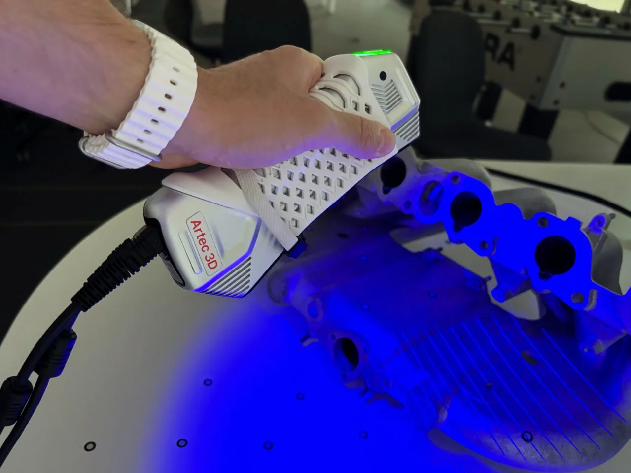

Editor’s note (September 2026): On August 5, 2026, Artec 3D released Artec Point II, which replaces Artec Point in the company’s metrology lineup. Point II keeps the certified 0.02 mm accuracy and the target-based workflow described below, but captures up to 5.8 million points per second, more than double the original, with 54 laser lines in ultra-fast mode, 17 parallel lines in hyperfine mode, and a single-laser mode for deep holes. Specifications and quotes below refer to the original Artec Point; read our Point II launch coverage for the current model.
Summary
Artec Point can be a strong 3D scanner for quality control when the job is dimensional inspection on parts large enough to justify a target-based workflow and when the acceptance process is validated on representative parts. Its manufacturer-stated headline specs are up to 0.02 mm 3D point accuracy, up to 0.02 mm resolution, and up to 120 FPS capture rate. [1]
In practical QC use, Artec Point is not a casual “scan and inspect” device. Artec lists volumetric accuracy up to 0.015 mm + 0.035 mm/m, or 0.015 mm + 0.015 mm/m with the Artec Metrology Kit, and the company’s FAQ states that Point is a target 3D scanner that requires attached targets. [1] Artec introduced Point in September 2024 and positioned it as its first target-based laser scanner. [2] That makes it relevant for part-to-CAD comparison and deviation analysis, but suitability still depends on tolerance level, part size, surface behavior, fixturing, and whether the full measurement workflow has been verified and validated for production use. [1] [19] [20]
What Quality Control Needs That “3D Modeling” Doesn’t
3D scanning for quality control is about answering a pass/fail question against a tolerance, not just creating a visually complete model. A scan can look clean and still be a poor inspection input if the workflow does not preserve geometry, alignment logic, traceability, and uncertainty context well enough to support an acceptance decision. [5] [14]
That is why metrology language matters. Point accuracy, volumetric accuracy, resolution, repeatability, and measurement uncertainty describe different aspects of performance, and mixing them up leads to weak validation plans and bad buying decisions. A metrology inspection scanner is judged less by how attractive a mesh looks than by how consistently the system supports comparison to CAD, deviation analysis, and tolerance checking under controlled conditions. [1] [5]
ISO 10360-13 frames this well: it is an acceptance and reverification test standard for optical 3D CMS, but its applicability depends on the scanned object being within a cooperative surface range. [14]
| Term | Plain-language meaning |
|---|---|
| Point accuracy | How close individual measured points are to the real surface. |
| Volumetric accuracy | How well size and position stay correct as measurement spans a larger volume. |
| Resolution | How finely the scanner can represent detail in the captured data. |
| Repeatability | How similar repeated results are when the same setup is used again. |
| Measurement uncertainty | The estimated range within which the true value is expected to lie. |
High resolution does not automatically mean high point accuracy, and good repeatability alone does not prove that a part is within tolerance.
How Artec Point Works
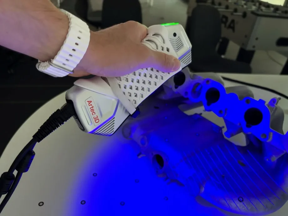
Artec Point is a handheld, target-based laser scanner, so tracking and registration depend on markers rather than target-free geometry capture. Artec launched it in September 2024 and described it as its first target-based laser scanner. [1] [2] In QC, that matters because targets are both a control aid and a workflow cost.
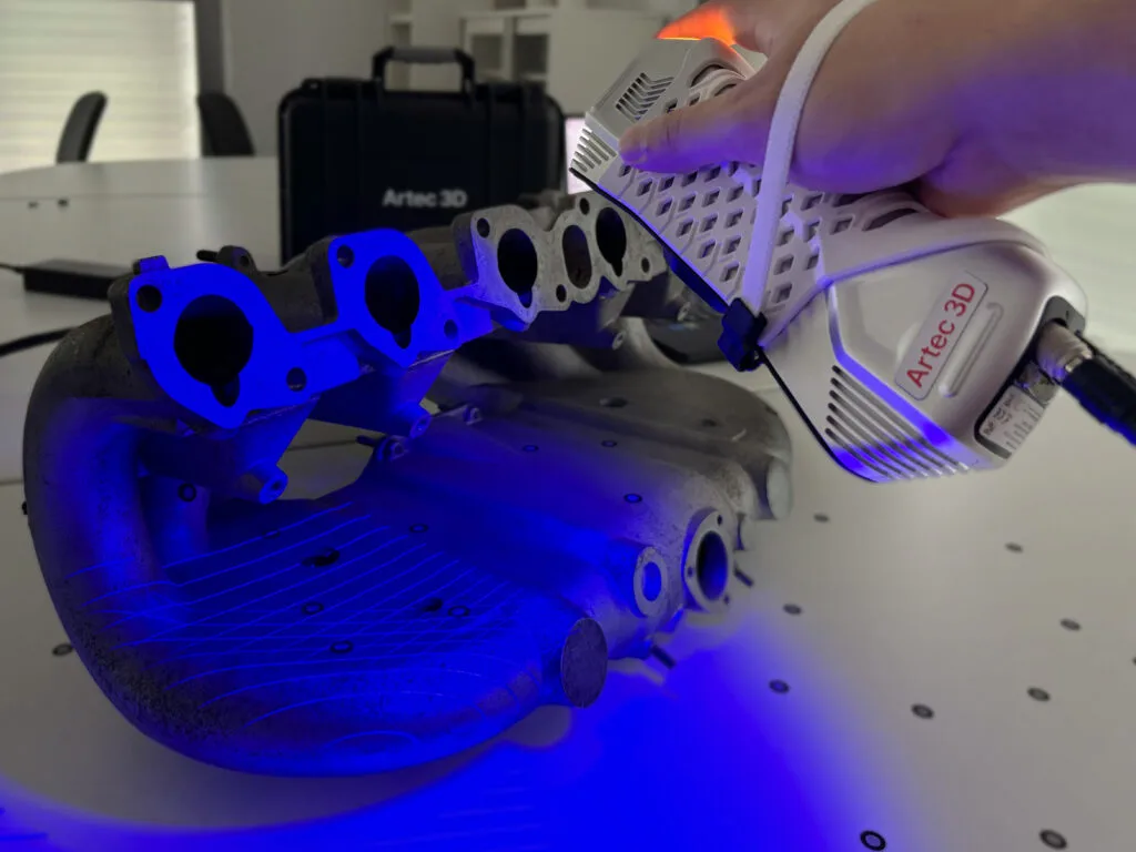
Artec Studio documentation says Artec Point uses a blue laser and two cameras whose fields of view intersect to form a common field of view. During scanning, more than four marker points must be present in that shared view. [4] In practice, results depend on more than the sensor alone: target layout, line of sight, operator movement, and how well the part stays within the usable tracking envelope all affect the scan. [4]
Artec Studio also notes that each new scanning session with Artec Point creates a new point cloud. [4] The native capture object is scan data, not a finished inspection artifact. The scanner acquires the surface, the software maintains registration through visible markers, and later processing turns that raw capture into the inspection object the workflow needs. [4] [5]
Artec Point scan modes, as stated by Artec:
- Ultra-fast: 17 crossed blue lasers. [1]
- Hyper-fine: 7 parallel blue laser lines. [1]
- Deep hole: 1 single blue laser line. [1]
One safety detail needs careful reading. Artec’s product page lists a “blue laser, class II (eye-safe),” while the Quick Start Guide labels Artec Point a “Class 2M laser product” and warns against direct or reflected exposure and against using optical devices such as magnifiers. [1] [3] Follow the latest official safety documentation and your workplace laser-safety rules rather than relying on the shorter product-page label alone. [1] [3]
Core Specifications
Vendor numbers are useful in QC only if they are read as stated capability under stated conditions, not as a guarantee for every part, operator, fixture, or alignment strategy. Point accuracy, volumetric accuracy, resolution, speed, and working envelope each answer a different question about inspection fit. [1]
All figures below are manufacturer-stated. The table separates nominal specification from the inspection context that determines whether the number is meaningful for your parts. [1]
| Metric | Artec Point (manufacturer-stated) | Why QC cares | Caveat / test-context note |
|---|---|---|---|
| Point accuracy | Up to 0.02 mm. [1] | Relevant to local surface fidelity in part-to-CAD comparison. | Manufacturer-stated value, not a full uncertainty budget. |
| Volumetric accuracy | Up to 0.015 mm + 0.035 mm/m, or 0.015 mm + 0.015 mm/m with Artec Metrology Kit. [1] | More relevant than point accuracy when error can accumulate across a larger part. | Manufacturer-stated; evaluate across actual part size and setup. |
| Resolution | Up to 0.02 mm. [1] | Affects how finely geometry can be represented in the data. | Resolution is not the same as measurement uncertainty. |
| Capture rate | Up to 120 FPS. [1] | Helps estimate acquisition speed. | 120 FPS is acquisition speed, not end-to-end inspection throughput. |
| Data acquisition speed | Up to 2.8 million measurements/s. [1] | Indicates potential point collection density and speed. | Dense data still needs stable tracking and clean processing. |
| Scanning area / working envelope | Scanning area 700 × 600 mm; depth of field 550 mm; working distance > 300 mm. [1] | Helps judge coverage, access, and operator path planning. | Geometry, occlusion, and target visibility still limit usable coverage. |
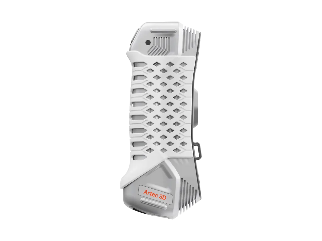
| Handling | Dimensions 203 × 80 × 44 mm; weight 570 g. [1] | Matters for access, fatigue, and scanner control over longer sessions. | Compact size does not remove target or line-of-sight overhead. |
| Connectivity / platform | USB 3.0; Windows 10 and 11. [1] | Affects workstation compatibility and deployment. | IT fit matters for traceability and reporting workflow. |
| Protection rating | IP50 dust protection. [1] | Useful for judging basic enclosure protection. | IP50 does not by itself prove readiness for every shop-floor environment. |
| Recommended PC | 64+ GB RAM and GPU with 8 GB VRAM. [1] | Processing speed affects practical throughput. | Underpowered hardware can become the bottleneck after capture. |
The key point is that Artec Point’s numbers describe stated device performance, not blanket production capability. Point accuracy and resolution are both listed at up to 0.02 mm, but they are not interchangeable. Volumetric accuracy usually matters more as part size grows, and high frame rate says nothing about whether your datum strategy, target plan, or deviation analysis will be stable enough for acceptance work. [1] [5]
A manufacturer-stated accuracy spec does not provide a complete, setup-specific measurement uncertainty budget for production acceptance; validate on representative parts and run an MSA/GR&R-style study if results will drive acceptance decisions. [1] [20]
Outputs & Exports: Point Clouds vs Meshes vs CAD Primitives
Artec Point natively captures point-cloud-based scan data. Artec Studio says each new Artec Point scanning session creates a new point cloud, and it defines a “Raw point cloud scan” as an object type from the Artec Point scanner or from imported point cloud data. [4] [5]
That is different from a mesh or a CAD object. In Artec Studio, a model is a polygonal mesh created by processing, while CAD primitives are analytical objects created in software. Artec Studio documentation states that CAD primitives can be exported to STEP, IGES, and XT, and point cloud export includes a Custom Text File Format described as raw point clouds from Artec Point. [5] [6] The Artec Point product page also lists mesh outputs such as OBJ, PLY, WRL, STL, AOP, ASC, Disney PTX, E57, and XYZRGB; CAD exports STEP, IGES, and XT; and measurement exports CSV, DXF, and XML. [1]
Treat Artec’s “output formats” as Artec Studio export capabilities; confirm required formats in a demo using your downstream software. [1] [4] [5] [6] The scanner hardware does not directly output finished CAD without software interpretation, cleanup, and export decisions. [5] [6]
Workflow: From Part to Report
Inspection time is wider than scan time. Artec Point’s up to 120 FPS capture rate helps data acquisition, but setup, targets, checks, processing, alignment, analysis, and reporting often determine the real cycle time. [1] 120 FPS is acquisition speed, not end-to-end inspection throughput. [1]
- Define the inspection objective. Decide whether the job is tolerance checking, part-to-CAD comparison, or model-versus-model review. That determines alignment logic and reporting needs. [5]
- Prepare the part, fixturing, and targets. Since Artec Point is target-based, the part or surrounding scene must support reliable marker visibility. [1] [4]
- Warm up the setup and check software and scanner readiness. Practical QC includes confirming the workstation, cable routing, and scene stability before capture. [1]
- Handle calibration or correction if needed, then verify separately. Artec’s documentation says correction is only a temporary measure and does not guarantee accurate geometric shapes or linear measurements. [7]
- Scan using the appropriate mode. Artec provides 17 crossed blue lasers, 7 parallel blue laser lines, and 1 single blue laser line for different geometry-access needs. [1]
- Choose the registration and alignment strategy. The result still depends on how scan data is aligned to CAD, datums, or another model. [5]
- Run deviation analysis and tolerance checking. Artec Studio’s Deviation analysis calculates a distance map between CAD and model or between two models, and the default search distance is 1 mm. [5]
- Export the report with traceability notes. For QC, the useful output is not just geometry but a documented result tied to setup and software context. [1] [5] [6]
Calibration, correction, verification, and validation are not synonyms. Artec Studio explicitly says correction does not guarantee accurate geometry or linear measurements and should be treated as a temporary measure until calibration is performed. [7] A separate verification check on an artifact is still needed if you want evidence that the measurement chain is behaving plausibly before scanning production parts. [7] [20]
For production use, reporting should preserve more than a color map. Another reviewer should be able to understand the scan mode, alignment logic, software version, target approach, and any exceptions that affected the result. [5] [6]
Validation & Measurement Risk
A spec sheet is not a production acceptance plan. Do not accept parts on the basis of manufacturer specs alone. [1] [19] [20]
First separate the control layers. Calibration or correction addresses scanner state; Artec says correction does not guarantee accurate geometric shapes or linear measurements. [7] Verification checks the process against a known reference or artifact. Validation goes further by testing the full inspection method on representative parts, surfaces, fixtures, and alignment or reporting choices. [7] [19]
That is where MSA and Gauge R&R matter. NIST describes Gauge R&R studies as a way to characterize gauges and instruments used in production in terms of the errors that affect measurements. [20] For a scan-based workflow, that usually means studying more than the scanner alone: part presentation, fixture repeatability, operator variation, target placement, and downstream analysis settings can all shift the result. [20] NIST’s paper on structured-light scanners makes the broader point that guideline-based tests and artifacts may not be sensitive to all error sources, and end users can be misled when the real application differs from the test conditions. [19] Even though that paper addresses another optical scanning class, the warning is still relevant to portable optical metrology workflows in general. [19]
No reliable device-specific measurement uncertainty budget was found in public Artec documentation; users must establish it for their own setup. If a release decision needs that number, it should come from internal validation data on the actual process, not from a product page. [1] [20]
Surfaces, Materials, and Geometry Limits
Optical metrology depends on what the system can see reliably, not just on the nominal accuracy in a spec table. ISO 10360-13 itself limits applicability to objects whose surface characteristics are within a cooperative range. [14]
Artec’s support documentation says optical scanners can struggle with dark, reflective, transparent, and translucent materials, and it suggests mitigations such as scanning spray or coating plus adjustments to angle and distance. [8] Those mitigations are conditional, not universal. Independent literature also shows that laser triangulation uncertainty is influenced by surface properties such as reflectivity and surface roughness, so a scan that works visually may still behave differently across finishes. [22]
Geometry adds another layer of risk. Deep holes, undercuts, narrow pockets, and other occluded regions can remain partially hidden from the cameras even when the rest of the scan looks complete. Artec’s single-line deep-hole mode is useful because the company specifically associates it with hard-to-reach areas and hole-like geometry, but it is still a constrained-access tool rather than a guarantee of full visibility. [1] Marker placement also matters, because Artec Studio requires more than four marker points in the common field of view during scanning. [4]
Transparent objects are harder still. A recent review states that transparent objects are challenging for optical detection because of complex refraction and reflection phenomena. [23] That is why transparent gemstones, glass-like inserts, and other see-through materials should be treated as boundary cases for scan-based inspection, not default fits. [8] [23]
Standards & “Certification” Context
Artec lists Artec Point’s certification as: “ISO 17025 accredited based on VDI/VDE 2634 & JJF 1951”. [1] Read carefully, that is not the same as saying every user scan is automatically ISO certified. ISO/IEC 17025 is a standard for testing and calibration laboratories, and ISO’s listing says the current edition was last reviewed and confirmed in 2023. [13] In other words, ISO/IEC 17025 is about laboratory competence and credibility of test or calibration work; it does not by itself certify every scan result produced later in the field. [13]
For optical 3D metrology, ISO 10360-13 is the relevant acceptance and reverification context, but ISO says the document applies only when the scanned object’s surface characteristics are restricted and within a cooperative range. [14] VDI/VDE 2634 Blatt 1 remains useful as triangulation-oriented context for mobile, flexible optical 3D measuring systems with imaging heads. [15] DIN Media lists VDI/VDE 2634 Blatt 2 and Blatt 3 as withdrawn, and both DIN Media and the DIN EN ISO 10360-13:2023-11 listing note the recommendation to use DIN EN ISO 10360-13:2023-11 instead. [16] [17] [18] That helps interpret the standards landscape, but it does not make all vendor specs directly comparable without test-context caution. [14] [19] JJF1951-2021 should be treated narrowly. The SAMR notice identifies it as “Calibration Specification for Optical 3D Measuring Systems Based on Structured Light Scanning,” approved on 2021-12-28 and implemented on 2022-06-28. [21] Because that title is structured-light-specific, it should not be stretched into a direct method-equivalence claim for a laser-based system unless an authoritative scope statement says so. [21]
Jewelry & Micro-Features
Jewelry is a boundary case here, not the center of the article. Artec Point is aimed at handheld metrology capture on larger workpieces than rings, prongs, pavé details, or gemstone seats usually imply. Transparent objects are also inherently difficult for optical measurement because refraction and reflection complicate detection. [23]
Artec’s own materials point toward Micro II for this size class. The jewelry solutions page positions Micro II as a desktop scanner for S/XS objects with 0.005 mm accuracy and 40 microns resolution, and the Micro II product page lists up to 5 microns accuracy, 2-micron repeatability, and object size up to 20 × 20 × 15 cm. [9] [10] For very small features or jewelry-scale inspection, that is a more credible system class than a handheld target-based scanner. [9] [10]
Decision Matrix: When Artec Point Fits
The practical selection question is simple: does your QC workflow benefit enough from portable, target-based laser capture to justify the setup and validation overhead? [1] [20]
Good fit if…
- The part is large enough that handheld coverage and a 700 × 600 mm scanning area are useful. [1]
- Target placement is acceptable in the inspection cell. [1] [4]
- The job centers on part-to-CAD comparison, deviation maps, or controlled dimensional inspection. [5]
- Surface prep is allowed when difficult finishes require spray or angle/distance adjustment. [8]
- The team will validate the workflow on representative parts before using it for release decisions. [19] [20]
Consider alternatives if…
- Parts are very small or micro-detailed and need a desktop small-object workflow instead. [9] [10]
- Transparent, highly reflective, or finish-variable surfaces would make preparation a constant burden. [8] [22] [23]
- The process cannot tolerate marker placement or registration overhead. [1] [4]
- The tolerance regime demands a validated uncertainty level that the team has not yet established internally. [20]
The hidden cost is often not capture but process discipline. If targets, surfaces, fixturing, and reporting are stable, Artec Point can fit well; if they are not, the risk shifts from scanning convenience to measurement credibility. [1] [19] [20]
Bottom Line: Is Artec Point the Right 3D Scanner for Quality Control?
Artec Point is a good fit when the task is dimensional, the parts are large enough to justify targets, and the team wants a portable metrology workflow that feeds part-to-CAD comparison and deviation analysis. Its manufacturer-stated specs make it relevant to QC discussions, and the software stack clearly supports point-cloud capture, comparison workflows, and export options that inspection teams care about. [1] [4] [5] [6] But the scanner is not target-free, not surface-agnostic, and not self-validating. [1] [4] [8]
As a 3D scanner for quality control, Artec Point is best judged by workflow fit rather than by headline accuracy alone. A manufacturer-stated accuracy spec does not provide a complete, setup-specific measurement uncertainty budget for production acceptance; validate on representative parts and run an MSA/GR&R-style study if results will drive acceptance decisions. [1] [20]
FAQ
1. Is Artec Point a good 3D scanner for quality control?
Yes, conditionally. Artec Point is credible for dimensional inspection when parts are large enough to benefit from handheld capture, the workflow can tolerate targets, and the team needs scan data that feeds comparison to CAD and deviation analysis. [1] [4] [5] It is less compelling when the process cannot absorb setup overhead or when surface behavior is too variable for stable inspection. [1] [8] The better question is whether your part family, tolerance band, and validation plan match a target-based portable metrology workflow. [19] [20]
2. Does Artec Point require targets, and what does that do to inspection time?
Yes. Artec’s product FAQ states that Point is a target 3D scanner and users need to attach targets, while Artec Studio documentation adds that more than four marker points must remain in the common field of view during scanning. [1] [4] That usually improves tracking stability, but it also adds preparation time, target management, and some fixture constraints. [1] [4] So even though capture can run at up to 120 FPS, the real inspection clock still includes target placement, scan review, cleanup, alignment, and reporting. [1] [5]
3. What’s the difference between point accuracy, volumetric accuracy, and measurement uncertainty?
Point accuracy describes local point closeness to the true surface, while volumetric accuracy describes how error behaves over a larger measurement span. Artec lists Point at up to 0.02 mm point accuracy and up to 0.015 mm + 0.035 mm/m volumetric accuracy, or 0.015 mm + 0.015 mm/m with the Artec Metrology Kit. [1] Measurement uncertainty is broader: it is the setup-specific estimate of how much the final result may differ from the true value after part presentation, operator effects, surfaces, alignment choices, and software processing are all included. [19] [20] Published scanner specs are inputs to uncertainty, not a substitute for it. [1] [20]
4. How should a QA team verify/validate a 3D scanning measurement system?
Start by separating scanner condition from process capability. Calibration or correction addresses scanner state, but Artec explicitly says correction does not guarantee accurate geometry or linear measurements. [7] Then run a verification check against a known artifact to make sure the workflow is behaving plausibly. [19] For production acceptance use, go further and run an MSA or Gauge R&R-style study on representative parts, fixtures, operators, and reporting settings, because NIST frames Gauge R&R as characterization of production measurement error. [20] The study should reflect the real process, not only a clean demo part, because NIST also warns that standard test artifacts may miss important error sources when applications differ from test conditions. [19]
5. Does Artec Point replace a CMM?
Not as a blanket claim. Artec Point may complement or speed up some inspection tasks, especially where noncontact coverage and portable access are useful, but replacement decisions depend on geometry, tolerance, datum strategy, access, and the uncertainty evidence your quality system requires. [1] [14] [20] Scan-based inspection can be highly useful, but it still needs workflow validation and should not be treated as automatically equivalent to every contact-metrology use case. [19] [20] If a team is asking “replace” rather than “fit for this measurement task,” it is usually asking the wrong first question.
6. How do black, shiny, or reflective parts affect scan-based inspection?
Artec’s support guidance says dark, reflective, transparent, and translucent materials can be difficult for optical scanners, and it recommends conditional mitigations such as spray or coating plus angle and distance adjustments. [8] Independent literature also shows that laser triangulation uncertainty is influenced by reflectivity and surface roughness. [22] In practice, that can mean missing data, noisier results, or extra preparation steps that change cycle time and measurement confidence. [8] [22] For QC, the issue is not just whether it can scan, but whether the resulting workflow remains stable enough for tolerance checking. [19]
7. Is Artec Point good for jewelry, rings, and transparent gemstones?
Usually no, or at least not as the default choice. Jewelry-scale parts push the workflow toward smaller-object systems, and transparent gemstones are especially problematic because optical measurement of transparent objects is challenged by refraction and reflection. [23] Artec’s own jewelry materials point to Micro II for S/XS objects, listing 0.005 mm accuracy and 40 microns resolution, while the Micro II product page lists up to 5 microns accuracy and 2-micron repeatability. [9] [10] That makes the desktop small-object class the more credible fit for rings and micro-features than a handheld target-based scanner. [9] [10]
Related on 3D Mag
Sources
- Artec Point product page
- Artec Point press release
- Artec Point Quick Start Guide
- Artec Studio 20 docs — Scanning with Artec Point
- Artec Studio 20 docs — Workspace and deviation analysis
- Artec Studio 20 docs — Projects, import, and export
- Artec Studio 20 docs — Calibration and correction caveats
- Artec Support Center — difficult surfaces
- Artec Micro II product page
- Artec jewelry solutions page
- Creaform HandySCAN BLACK Series page
- Creaform MetraSCAN BLACK+ Elite technical specifications
- ISO/IEC 17025:2017 listing
- ISO 10360-13:2021 listing
- VDI/VDE 2634 Blatt 1 listing
- DIN Media listing — VDI/VDE 2634 Blatt 2
- DIN Media listing — VDI/VDE 2634 Blatt 3
- DIN EN ISO 10360-13:2023-11 listing
- NIST — Sources of Errors in Structured Light 3D Scanners
- NIST/SEMATECH — Gauge R&R studies
- SAMR notice listing JJF1951-2021
- PubMed abstract — measurement uncertainty in laser triangulation influenced by surface properties
- Light: Science & Applications review — transparent objects are challenging for optical measurement