
Summary
Optimal line width in FDM/FFF printing is not one universal number. It is the slicer’s nominal target width for a deposited toolpath, and common 0.4 mm profiles start in slightly different places. Cura binds line_width to a 0.4 mm machine_nozzle_size, PrusaSlicer’s guidance centers on about 110% of nozzle diameter with an automatic rule of 1.125× when the field is set to 0, and a common Bambu Studio process profile uses 0.42 mm globally with wider values for some features. [2] [3] [4]
Quick answer — what line width means and what to use for a 0.4 mm nozzle
Optimal line width, in practical terms, means choosing a sensible starting width for the feature you are printing rather than chasing one magic number. If you are asking what line width should I use for a 0.4 mm nozzle, start with the printer or slicer profile and treat extrusion width as a feature-by-feature control, not a universal rule. [2] [3] [4]
For common cited 0.4 mm profiles, a reasonable starting range is about 0.40-0.45 mm for general printing, with wider first layers often used only for adhesion. Cura’s base default is 0.4 mm and equals machine_nozzle_size. [2] Prusa’s guidance says extrusion width is generally about 110% of nozzle diameter, and if the field is set to 0, PrusaSlicer derives it as 1.125× nozzle diameter, which is 0.45 mm on a 0.4 mm nozzle. [3] A common Bambu Studio process profile uses 0.42 mm for line_width, 0.45 mm for inner_wall_line_width, and 0.50 mm for initial_layer_line_width. [4] Those are profile examples, not a universal optimum. [2] [3] [4]
| Feature | Starting value | Why | Caveat |
|---|---|---|---|
| Default or outer wall | near 0.40-0.42 mm | detail and predictability | Cura and Bambu profile examples only. [2] [4] |
| Inner wall / infill | about 0.42-0.45 mm | overlap and throughput | Profile- and machine-dependent. [3] [4] |
| First layer | 0.48-0.56 mm on a 0.4 mm nozzle, or a profile default such as 0.50 mm | adhesion | Reduces XY resolution. [3] [4] |
| Support | tuned for removability | easier breakaway can matter more than maximum bonding | Material and slicer dependent. [3] |
Terminology and standards — line width, extrusion width, nozzle diameter, and MEX
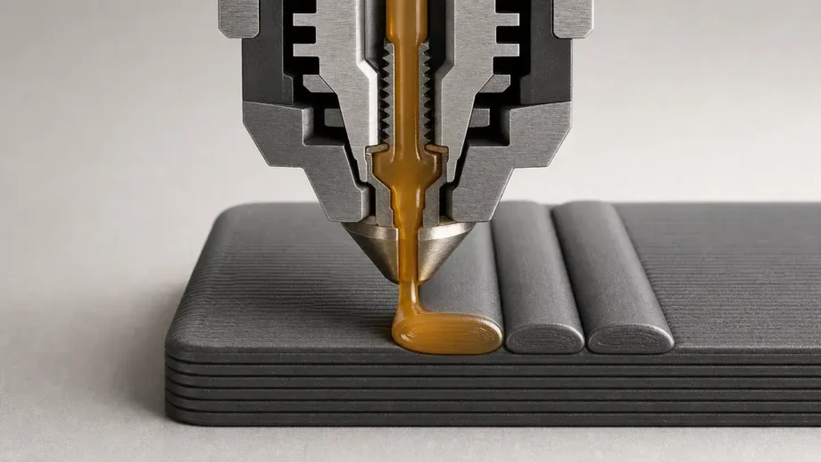
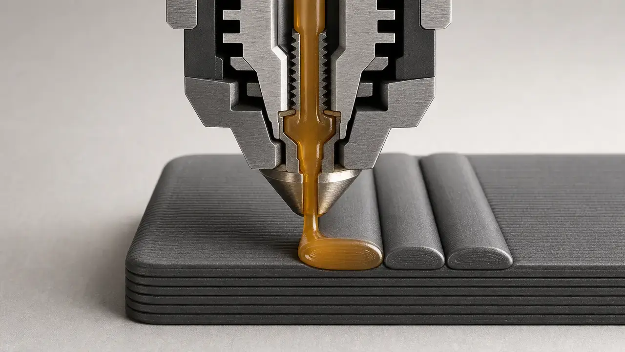
In FDM/FFF, line width is the slicer’s nominal target width for a deposited toolpath. Nozzle diameter is the physical orifice size. Measured bead width is the actual width of the deposited strand after extrusion and flattening, while toolpath spacing is the distance the slicer chooses between adjacent paths. These ideas are related, but they are not interchangeable. Line width is a slicer target, not a guarantee that a caliper-measured strand will match it exactly. [2] [7]
For standards language, FDM/FFF sits under material extrusion, or MEX, in ISO/ASTM 52900:2021, which defines the process class as additive manufacturing in which material is selectively dispensed through a nozzle or orifice. [1] Modern slicers can also vary line width locally, especially for thin walls and gap filling, so one fixed number is not always used everywhere in a print. [7] That standards label is useful for taxonomy, but it does not turn one slicer setting into a universal best practice. [1] [7]
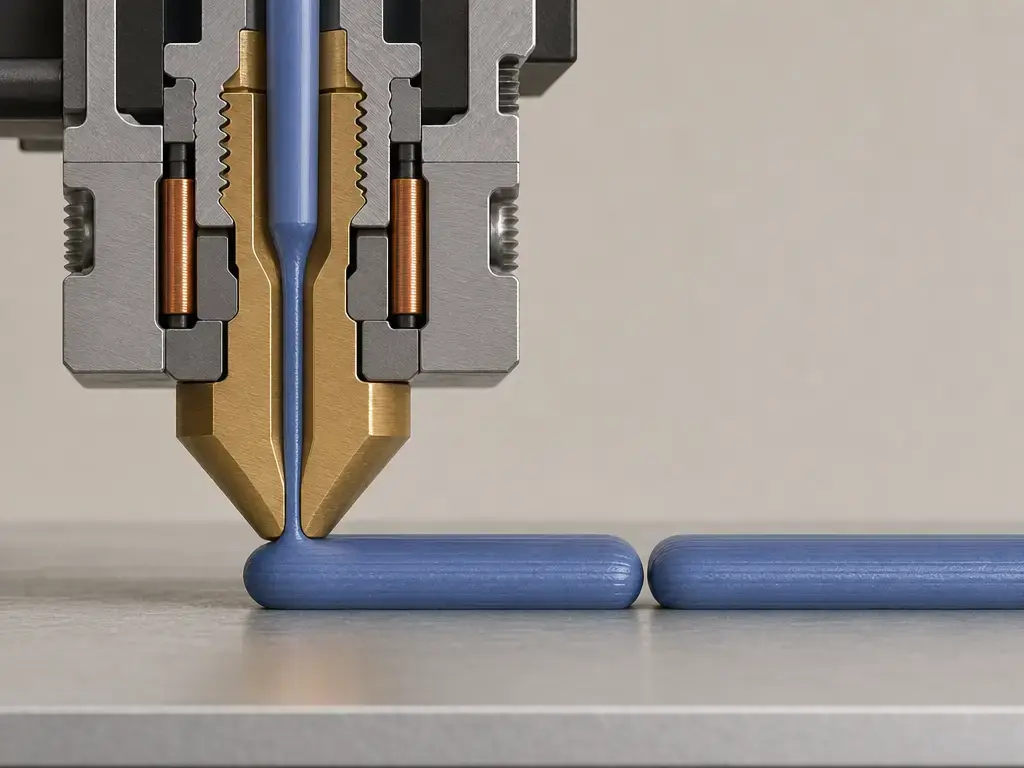
The geometry behind line width — layer height, flow rate, extrusion multiplier, and toolpath spacing
Line width changes how much plastic the printer must deliver per unit of path length, so it interacts with speed and the machine’s real material-delivery capacity. If you ask for wider roads at the same print speed, the printer must push more material per second. That is why line width settings are usually coordinated with the rest of the profile instead of changed in isolation. [2] [3]
Layer height is a separate setting from line width, even though the two are often discussed together. Prusa’s guidance says maximum layer height should be about 70-80% of nozzle diameter. [3] On a typical 0.4 mm nozzle, that means the layer-height discussion should stay separate from the line-width discussion rather than collapsing both into one “nozzle rule.” [3] If a flow or extrusion-multiplier setting is changed, the measured bead width can also shift away from the slicer’s nominal target. [2] [8]
Slicers and firmware realize those choices indirectly. Common Marlin-documented G-code exposes motion commands such as G0/G1 and extrusion-mode commands such as M82/M83, but no reliable universal line-width field was found in common Marlin G-code. [8] In practice, slicer output line width is usually encoded through toolpath geometry and extrusion amount, not through one standard visible width parameter. [8]
How slicers use line width
Slicers do not usually apply one universal width to every path. Instead, they expose multiple line width settings in slicer profiles because visible outer walls, inner walls, top surfaces, infill, support, and first layers do different jobs. Cura uses “Line Width” plus feature-specific child settings. [2] PrusaSlicer uses “Extrusion width,” and if the field is set to 0, it derives width as 1.125× nozzle diameter. [3] Bambu Studio exposes profile fields such as line_width, inner_wall_line_width, support_line_width, top_surface_line_width, and initial_layer_line_width. [4]
Common slicer line-width fields to explain:
- Default / global line width
- Outer wall line width
- Inner wall line width
- Infill line width
- Top/bottom line width
- Support line width
- Skirt/brim line width
- Initial / first-layer line width
Wall thickness is not the same thing as wall line width. Cura’s profile logic states that wall thickness divided by wall line width defines the number of walls. [2] In the same base definition, wall_thickness defaults to 0.8 mm and wall_line_count defaults to 2. [2] That is why changing wall line width can change wall count when wall thickness stays fixed, and why feature-specific overrides are normal rather than exceptional. [2] [4]
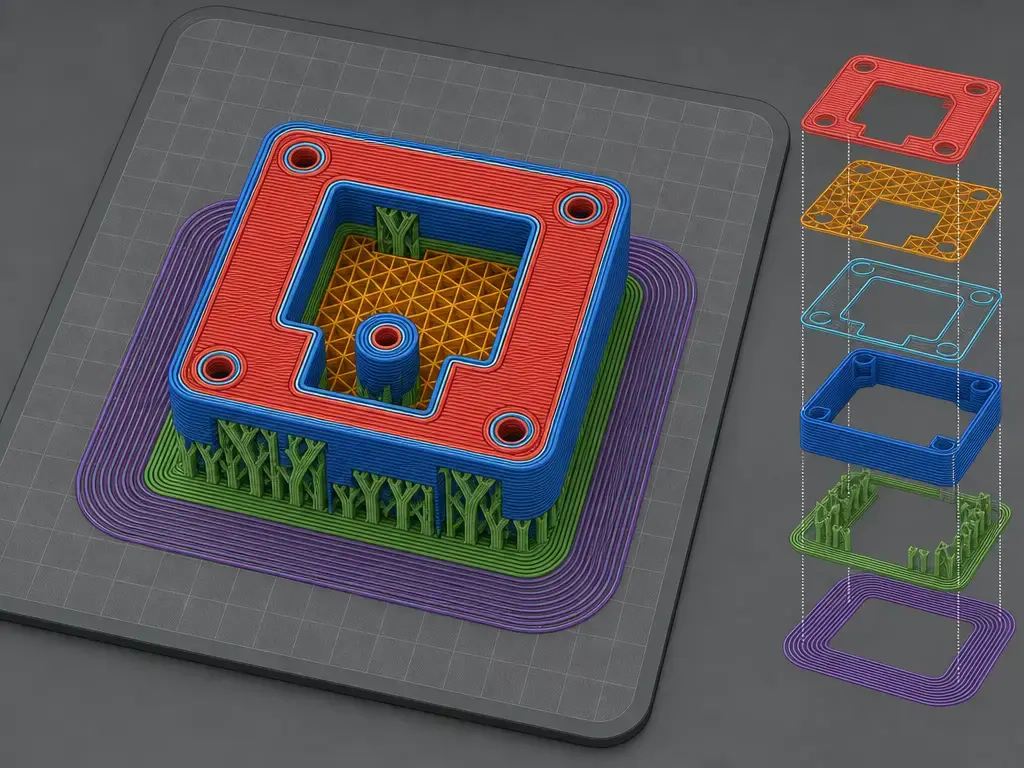
How to choose the optimal line width for nozzle size
For a 0.4 mm nozzle, the safest starting point is the printer or slicer profile, not a universal optimum. Common cited profiles cluster near nozzle diameter or slightly above it, but they do not all use the same number. [2] [3] [4]
If your goal is predictable detail, start near nozzle diameter because that is how Cura’s base definition is framed and how many 0.4 mm examples are built. [2] If your goal is a slightly fuller road, Prusa’s general guidance of about 110% puts a 0.4 mm nozzle near 0.44 mm, and its 0 auto rule yields 0.45 mm. [3] If you are comparing modern 3D printing line width examples, Bambu’s common process profile shows 0.42 mm globally, 0.45 mm for inner walls, and 0.50 mm for the initial layer. [4] That pattern is useful because it separates “start here” from “change this later.” Outer walls usually stay conservative first, while inner walls, infill, and first layers are more common places to widen paths for throughput or adhesion. [2] [3] [4]
| Setting choice | Typical reason | Main trade-off | Source / caveat |
|---|---|---|---|
| Near nozzle diameter | predictable detail and profile defaults | may take longer | Cura-style baseline. [2] |
| Slightly wider than nozzle | stronger overlap or tuned profiles | can reduce fine detail | Prusa and Bambu examples. [3] [4] |
| Wider infill | faster internal fill | higher material demand | Slicer-dependent. [2] |
| Wider first layer | adhesion | lower XY resolution | Profile-specific. [2] [3] [4] |
Cura’s warning formulas help explain the software side of the decision, but they are not engineering limits. Its minimum warning formula for line width is 0.1 + 0.4 × nozzle size, its general maximum warning is 2 × nozzle size, and infill_line_width uses a wider maximum warning of 3 × nozzle size. [2] Treat Cura’s warning bounds as UI warnings only. [2] Prusa’s practical guidance of about 110% and first-layer examples of 120-140% of nozzle diameter show one manufacturer’s starting logic, while Bambu’s default fields show another. [3] [4]
Feature-specific line width choices
Outer walls are the most visible paths, so they usually deserve the most conservative line-width choices first. Inner walls can often be slightly wider because they are less visible and more relevant to overlap and throughput. Infill is usually the most flexible field because it is primarily internal structure rather than finished surface. Top and bottom surfaces sit between those priorities: they affect both enclosure quality and visible finish, so they are less forgiving than bulk infill. [2] [4]
Support, skirt, brim, and first-layer settings follow different priorities. Prusa explicitly notes that reducing support-material extrusion width can make supports weaker and easier to remove. [3] Cura’s initial_layer_line_width_factor defaults to 100% and uses a 150% warning threshold, which shows that the first layer is handled as a special case rather than as a rule for the whole print. [2] A common Bambu Studio process profile likewise uses a wider first layer at 0.50 mm than its 0.42 mm global width, while keeping top_surface_line_width at 0.42 mm and support_line_width at 0.42 mm. [4]
What line width changes in print quality, strength, and print time
Does line width affect strength and print quality? Yes, but not in one simple direction for every print. Wider lines can improve overlap or reduce voids in some setups, but they can also worsen corner fidelity, small holes, and mating fits. [5] [6] Line width is only one variable among material, nozzle size, layer height, speed, orientation, and flow behavior. [5] [6]
In a 2025 PETG study using a 0.4 mm nozzle, line widths of 0.4, 0.6, and 0.8 mm, layer heights of 0.1, 0.2, and 0.3 mm, and print speeds of 25, 35, and 45 mm/s were tested. [5] Under those PETG-only conditions, tensile strength at 25 mm/s increased from 48.37 MPa at 0.4 mm line width to 50.28 MPa at 0.8 mm, and at 45 mm/s it increased from 47.15 MPa to 48.44 MPa. [5] In the same study and under that same scope, the predicted optimum was 0.12 mm layer height, 0.76 mm line width, and 25.7 mm/s, with validation run at 0.77 mm line width and 25.75 mm/s. [5]
A separate 2023 PLA total-contact-cast study used 36 treatments with line widths of 0.4, 0.6, 0.8, and 1.0 mm and layer heights at 30%, 50%, and 70% of line width for that specific geometry. [6] Under those PLA total-contact-cast conditions, line width was not statistically significant for flexural modulus, with p = 0.386. [6] The same study reported average print-time reductions of 46.9% when moving from 0.4 mm to 0.6 mm line width and 66.2% when moving from 0.4 mm to 1.0 mm. [6]
Taken together, those studies support a narrow conclusion: changing line width can materially affect print time and can affect mechanical results, but the effect is not universal across materials or part geometries. [5] [6] That is why dimensional accuracy, visible surface quality, and strength all have to be judged in the context of the specific part instead of by nozzle diameter alone. [5] [6]
When wider or narrower line width makes sense
Wider line width use cases
Wider lines make the most sense when throughput, overlap, or first-layer grip matters more than micro-detail. That can include some inner walls, some infill strategies, and first layers where better bed contact is worth a reduction in XY resolution. [2] [3] The PLA total-contact-cast study is a useful reminder that wider lines can shorten production time for a real part, but that result was tied to one geometry and should not be treated as a universal recommendation for every print. [6]
Narrower line width use cases
Narrower lines make more sense for visible outer surfaces, small text, sharp edges, and parts with tighter mating requirements. Because Cura links wall count to wall thickness and wall line width, even small width changes can alter how shells are resolved if wall thickness is held constant. [2]
Before changing extrusion width in FDM printing, check:
- Nozzle diameter selected in the slicer
- Layer height
- Feature type being changed
- Print speed and volumetric demand
- Flow / extrusion multiplier
- Wall thickness and wall count
- Small features and text
- Mating tolerances
- First-layer adhesion
In short, how to choose extrusion width in FDM printing is a feature-priority question, not a single number you apply everywhere. [2] [3]
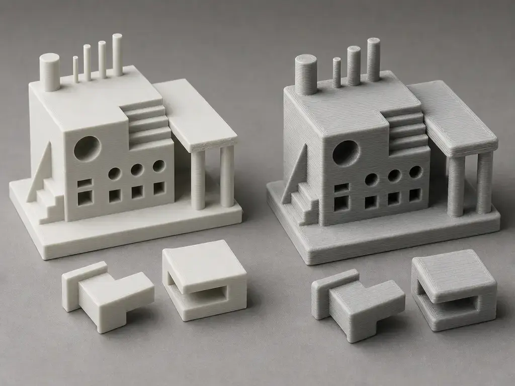
Limitations, failure modes, and G-code reality
Pushing line width too far without adjusting the rest of the process can backfire. Likely failure modes include under-extrusion when the machine cannot supply the requested material fast enough, rough top surfaces, drifting dimensions, poor corners, and weak bonding if layer height is also pushed too high for the nozzle. Wider outer lines can reduce path count but may worsen sharp corners, small holes, and mating fits. [6] Treat Cura’s warning bounds as software warnings, not engineering limits. [2] They are useful for UI feedback, but the formulas themselves do not prove that a given width will print well on a specific printer, material, and part. [2]
At the firmware level, no reliable universal line-width field was found in common Marlin G-code. Marlin documents motion and extrusion-mode commands such as G0/G1 and M82/M83, so line width is usually implicit in path geometry and extrusion amount rather than explicit as one standard parameter. [8]
Current research and standards context
The cited literature supports a multi-factor view of optimal line width rather than a nozzle-only rule. The PETG paper shows that an “optimum” can emerge from a combination of line width, layer height, and speed, while the PLA total-contact-cast paper shows geometry-specific throughput benefits without proving one universal best width. [5] [6]
That evidence hierarchy matters. Use MEX for the standards taxonomy. [1] Use official slicer documentation for defaults and naming. [2] [3] [4] Use peer-reviewed studies for performance claims, and keep those claims tied to the tested material, geometry, and process window. [5] [6]
Practical guidance — a safe decision sequence
- Start from the printer or slicer profile for your nozzle size. [2] [3] [4]
- Keep outer walls conservative until surface quality is proven on your machine. [2] [4]
- If you want more throughput, adjust inner walls or infill before changing everything else. [2] [4]
- Widen the first layer only when adhesion needs it, and remember the XY-resolution trade-off. [2] [3] [4]
- Recheck wall thickness, wall count, feature size, and fit after any wall line width change. [2]
- Treat “optimal” as optimal for a profile, feature, material, and goal. [3] [5] [6]
Those steps line up with Cura’s 0.4 mm baseline, Prusa’s 110% and 120-140% examples, and Bambu’s feature-specific defaults. [2] [3] [4]
FAQ
Here are short answers to the most common line-width questions.
What line width should I use for a 0.4 mm nozzle?
Start with the printer or slicer profile. On common cited 0.4 mm systems, that usually means roughly 0.40-0.45 mm for general printing, not because that range is universally best, but because Cura starts at 0.4 mm, Prusa’s guidance lands near 0.44-0.45 mm, and a common Bambu profile uses 0.42 mm globally with 0.45 mm inner walls. [2] [3] [4] Use a wider first layer only if adhesion needs it. [2] [3] [4]
What is the difference between line width and nozzle size?
Nozzle size is the physical orifice diameter. Line width is the slicer’s target width for the deposited road. They are related, and many profiles start near nozzle diameter, but they are not guaranteed to be identical in the finished bead. [2] [3] If you change wall line width while keeping wall thickness fixed, the slicer may also recalculate wall count. [2]
Is extrusion width the same as line width in FDM printing?
Usually yes in slicer discussions, but the naming depends on the software. Cura uses “Line Width,” while PrusaSlicer uses “Extrusion width.” [2] [3] Modern slicers can also vary width locally in thin walls and gap-filling regions, so the print may not use one fixed width everywhere. [7]
How do I choose extrusion width in FDM printing?
Start from the working nozzle profile, then choose by feature priority. Keep outer walls conservative for visible detail, allow somewhat wider inner walls or infill if throughput matters, and widen first-layer settings only when adhesion needs it. [2] [3] [4] After that, recheck layer height, speed, wall thickness, wall count, and fit, because extrusion width changes can ripple into the rest of the sliced part. [2] [3]
Does line width affect strength and print quality?
Yes, but conditionally. In the PETG study with a 0.4 mm nozzle, 0.4/0.6/0.8 mm line widths, 0.1/0.2/0.3 mm layer heights, and 25/35/45 mm/s print speeds, tensile strength increased as line width increased under the tested conditions. [5] In the PLA total-contact-cast study, line width was not significant for flexural modulus, with p = 0.386, even though wider lines reduced print time for that geometry. [6] So wider lines can help some outcomes while hurting corner fidelity, hole accuracy, or mating fit in others. [5] [6]
Can a 0.4 mm nozzle print 0.6 mm or 0.8 mm line width?
Sometimes yes, but only in specific setups. The PETG study explicitly tested 0.6 mm and 0.8 mm line widths on a 0.4 mm nozzle, alongside multiple layer heights and speeds. [5] That does not make those widths universally safe or appropriate for every printer, hotend, polymer, or part geometry. [5]
Should first layer line width be larger?
Often yes, because extra contact area can improve adhesion. Cura handles this as a first-layer multiplier with a 100% default and a 150% warning threshold, while Prusa gives first-layer examples at 120-140% of nozzle diameter and a common Bambu process profile uses 0.50 mm for the initial layer. [2] [3] [4] The trade-off is lower XY resolution on that layer, so it is best treated as a first-layer-only choice. [2] [3] [4]
Sources
- [1] ISO/ASTM 52900:2021 — Additive manufacturing — General principles — Fundamentals and vocabulary. https://cdn.standards.iteh.ai/samples/74514/57d795b6267a427899d7b351598bece2/ISO-ASTM-52900-2021.pdf
- [2] UltiMaker Cura
fdmprinter.def.json. https://raw.githubusercontent.com/Ultimaker/Cura/main/resources/definitions/fdmprinter.def.json — GitHub branch-head snapshot accessed 2026-07-28; freeze to a commit hash or archived revision before publication. - [3] Prusa Knowledge Base — Creating profiles for different nozzles. https://help.prusa3d.com/article/creating-profiles-for-different-nozzles_127540?product=mk3s-2
- [4] Bambu Studio profile file —
fdm_process_common.json. https://github.com/bambulab/BambuStudio/blob/master/resources/profiles/BBL/process/fdm_process_common.json — GitHub branch-head snapshot accessed 2026-07-28; freeze to a commit hash or archived revision before publication. - [5] Frontiers in Bioengineering and Biotechnology — “Optimization of PETG 3D printing parameters for the design and development of biocompatible bone implants.” https://www.frontiersin.org/articles/10.3389/fbioe.2025.1549191/full
- [6] Annals of 3D Printed Medicine / ScienceDirect — “Preliminary assessment on the effects of line width, layer height and orientation on strength and print time for FDM printing of total contact casts for the treatment of diabetic foot ulcers.” https://www.sciencedirect.com/science/article/pii/S2666964123000164
- [7] UltiMaker article — “Unlock the power of variable line width with Ultimaker Cura 5.0.” https://ultimaker.com/de/learn/unlock-the-power-of-variable-line-width-with-ultimaker-cura-5-0/
- [8] Marlin Firmware G-code index. https://marlinfw.org/meta/gcode/