
Summary
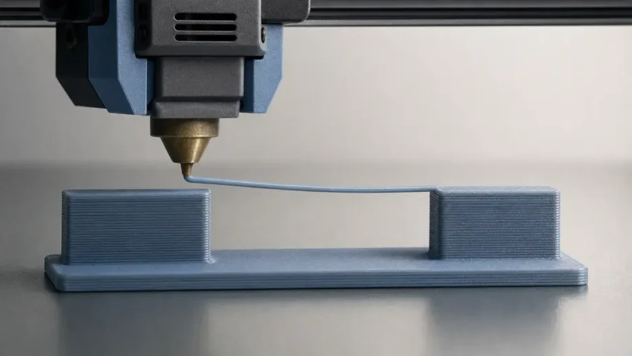
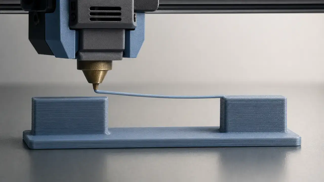
3D printing bridging is unsupported extrusion across a gap in FFF/FDM material extrusion, with the standards-aligned process term being material extrusion, or MEX. A practical reader-facing definition from Prusa is simply printing “over thin air” without supports, and that is the working definition used here. ISO lists ISO/ASTM 52900:2021 as Edition 2, 28 pages, published on November 16, 2021, and last reviewed and confirmed in 2025, while Stratasys lists FDM as one of its trademarks. [6] [1] [4]
In practice, the main questions are when slicer bridge detection actually turns on, how bridge speed, bridge flow, and bridge fan settings interact, and what quality target matters most: no visible sag, a cleaner underside, or simply a closed gap. The sources do not support one universal preset or one universal maximum span. Cura’s bridge overrides are version-specific defaults, manufacturer guidance is equipment-specific, service-bureau rules are finish-focused, and published studies show setup-dependent outcomes rather than a single hard limit. PLA often bridges more easily than PETG in everyday use, but that tendency is still profile-dependent, and resin spans belong to a different support-and-orientation problem set. [9] [10] [11] [8] [12] [18] [20]
Why bridging matters in FFF design
Bridging matters because supports are useful but costly. In FFF printing, supports add material, print time, cleanup work, and the risk of visible marks where the support touched the part, so users often try to replace a supported ceiling with a short unsupported bridge when the geometry allows it. That makes bridging a practical design exception, not a magic capability: it can save post-processing and preserve surface finish on the underside, but only within the limits of the printer, material, cooling, and span geometry. [11]
Standards and terminology: MEX, FFF, and the FDM trademark note
For standards-based terminology, the umbrella process name is material extrusion, usually shortened to MEX. ISO/ASTM 52900:2021 is the additive-manufacturing vocabulary standard that supports that wording, and ISO currently lists the 2021 edition as Edition 2, 28 pages, published on November 16, 2021, with the standard confirmed in 2025. ASTM’s description of the newer F3529 guide also frames MEX as a layer-based additive process that deposits a filament or bead from an extrusion head, and NIST separately lists Material Extrusion as one of its additive-manufacturing technology areas. [1] [3] [5]
Reader-facing articles still need familiar language, so FFF and FDM remain useful terms in context. FDM is a Stratasys trademark, which is why generic technical writing often prefers material extrusion or FFF when it wants non-brand wording. ASTM F3529-21 also exists as an active 22-page design guide for polymer material extrusion, last updated on the ASTM store page on February 10, 2022, but that guide should not be treated as a source of universal bridge-span numbers. [4] [2]
What is bridging in 3D printing?
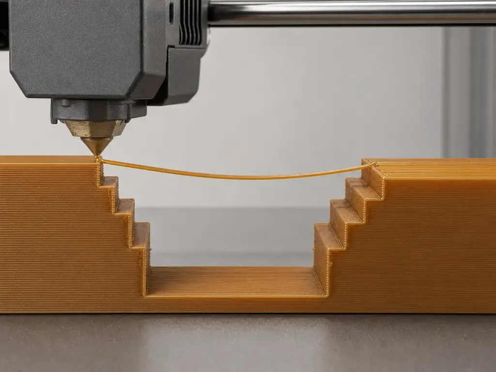
In 3D printing bridging, the printer lays down an unsupported strand across a gap between two supported endpoints. In standards language this sits inside material extrusion, but for hobby readers it is the familiar FFF/FDM case where a thermoplastic road is deposited in open air long enough to cool and hold shape. The key geometry variable is the span length between those anchor points, because that unsupported distance changes how much the strand can sag, separate, or distort before later layers land on top of it. Prusa’s “over thin air” definition is useful because it captures the core behavior without implying that every unsupported feature is the same kind of problem. [6] [1]
A bridge has supported endpoints; an overhang may not. FDM remains a trademarked term, so MEX or FFF is usually cleaner in generic technical writing even when hobby users still say FDM. [4]
Bridge vs overhang vs support interface vs resin span
These terms are easy to blur together in slicer preview, but they do not fail for the same reasons. In FFF printing, a bridge is a support-avoidance case across a real gap, while a resin “bridge” is usually dominated by orientation, peel forces, and support strategy rather than filament-style bridge tuning. [11] [12]
| Feature | Supported where? | Main risk | Typical fix |
|---|---|---|---|
| FFF bridge | Both ends | Sagging or strand separation. [11] | Tune bridge speed, flow, and cooling, or shorten the span. [6] |
| Overhang | One side or partial support below | Curling or droop. | Change orientation, improve cooling, or add supports. [6] |
| Support interface | Sacrificial material below | Rough underside after removal. | Adjust support placement and interface strategy. [11] |
| Resin span | Supports plus peel/separation forces | Warp, detachment, or failure. [12] | Reorient the part and add supports. [12] |
Use the table as a triage tool. If the geometry is a true gap between two supported edges, bridge settings or a redesign are the first places to look. If it is a projecting surface, cooling and angle changes may solve it without invoking bridge logic at all. If it is resin, orientation and supports matter more than bridge-speed logic. [6] [12]
Bridge quality: what to measure
Good bridging is not a simple pass-or-fail condition. A bridge can close a gap and still be poor if the underside is ugly, the span droops too far, or the upper surface ends up dimensionally wrong. [18] [20]
The most useful bridge-quality metrics are sag/deflection, underside surface quality, strand separation or gaps, dimensional error, top-surface closure, and delamination or cracking. The 2021 dimension-error study used a straightforward caliper method, comparing measured deck thickness with the designed value over test spans from 25 mm to 43 mm, which is a good example of turning “that looks bad” into repeatable data. The 2026 PLA beam study evaluated bridging condition qualitatively through deflection, slope, and delamination defects, and also modeled buckling behavior as span increased, including girder-width changes from 1.2 mm to 4.3 mm over 60 mm to 140 mm spans. [20] [18] [19]
A practical inspection routine is simple: photograph the underside, inspect the bridge from the side, and measure one consistent feature every time with calipers. Also check slicer preview so you know whether the software treated the region as bridge skin, bridge walls, or some other toolpath category, because those regions can behave differently. Visual inspection alone is useful, but visual inspection plus one consistent measurement is stronger when comparing span length, layer height, line width, or a bridge-specific override. [20] [9] [14]
Bridge test checklist:
- Use one spool for the whole comparison, and dry it first if moisture is in doubt. [21]
- Record nozzle temperature, fan percentage, bridge speed, bridge flow or bridge flow ratio, layer height, nozzle or line width, and the span lengths tested. [9] [14]
- Change one variable at a time. [6] [20]
- Photograph the underside and side profile with the same lighting and distance each round. [20]
- Do not treat one printer-material result as a universal bridge setting. [18] [20]
Why bridges sag (and why cooling can backfire)
A useful working model is that a bridge is a hot, still-soft strand that has to span a gap before it fully solidifies. In that short window, gravity acts on the strand, the polymer is still flowing and relaxing, and nozzle motion affects how much the extrusion is stretched between the two anchor points. That helps explain why bridges often improve when the printer gives the strand less time to droop, but it is still a simplified explanation rather than a complete physical law for every printer and polymer. Prusa’s troubleshooting framework is practical for this reason: it reduces the problem to settings, speed, and cooling, which are the three levers most users can actually control. [6] [18]
What usually worsens sagging is some combination of too much heat, too much bridge flow, insufficient cooling, or a span that is simply too long for the setup. Those same causes show up in the metrics above: deeper sag, more visible roping underneath, gaps between adjacent bridge lines, or a top surface that never fully closes. Longer spans usually amplify the problem because the strand has more unsupported distance to survive before the next layers arrive. [6] [18]
Cooling helps shape retention, but it can also narrow the bonding window. The 2026 study explicitly notes that rapid cooling can mitigate sagging while also weakening adhesion between filaments, so a bridge that looks flatter is not automatically a bridge that bonds better. [18]
Bridging settings in the slicer (FFF/MEX-only)
Bridge settings are overrides, not universal print presets. They matter only when the slicer recognizes a region as a bridge and applies bridge-specific behavior, so preview inspection is part of the workflow. In Cura 5.12.1’s base definition file, bridge_settings_enabled defaults to false, and bridge_wall_min_length defaults to 5 mm, meaning short unsupported walls may still print with normal wall logic instead of any bridge override. The same file documents default bridge-wall and bridge-skin speeds of 15 mm/s, bridge-wall flow of 50%, bridge-skin flow of 60%, and bridge fan speed of 100%, but those are software defaults for that version, not universal best practice. [9]
Across slicers, the concepts are similar even when the names differ. Prusa advises tuning bridge flow ratio and bridge speed by testing rather than offering one fixed number. OrcaSlicer documents bridge_flow and internal_bridge_flow, bridge-density controls, thick bridges, extra bridge layers, and bridge-angle behavior. SuperSlicer documents the same idea of a bridge-angle override, with automatic calculation at 0 and 180° treated as the zero-angle reference. Bambu Studio release notes also show bridge-specific controls exist by referring to Bridge flow under Quality Settings and to per-part bridge-speed behavior. [6] [14] [15] [16] [17]
Use these settings names as concepts rather than as a universal UI map:
- Bridge speed is a bridge-only speed override. [6] [9]
- Bridge flow or bridge flow ratio is a bridge-only extrusion override, not the same thing as global flow or an overall extrusion multiplier. [14] [9]
- Bridge fan speed or cooling override changes cooling behavior specifically for bridge regions where the slicer supports it. [7] [9]
- Bridge detection and minimum bridge length thresholds decide whether bridge logic runs at all. Cura 5.12.1 documents a 5 mm default bridge-wall threshold in its base definition. [9]
- Bridge skin density or bridge density affects bridge-line spacing and can influence both underside appearance and top-surface support. [9] [14]
- Bridge angle or direction override is slicer-dependent. OrcaSlicer and SuperSlicer both document it. [15] [16]
- Thick bridges or bridge line-height behavior is slicer-dependent. OrcaSlicer documents thick bridges as using a line height equal to the nozzle diameter. [14]
- Temperature and the filament profile still matter, even though they are not always grouped under “bridge” settings. [6] [21]
Global flow affects all extrusion, while bridge flow ratio affects only segments the slicer has classified as bridges. In OrcaSlicer, the actual bridge flow is calculated from the bridge setting together with the filament flow ratio and, if present, the object flow ratio. [14]
How far can you bridge?
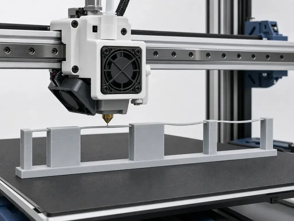
There is no reliable universal maximum bridge span. The better question is which outcome you want: a gap that merely closes, a bridge with almost no visible sag, or a production-quality underside that stays dimensionally faithful. Printer geometry, nozzle size, span length, cooling, bridge detection rules, material behavior, and the quality target all change the answer, which is why slicer defaults, manufacturer examples, service-bureau rules, and published studies do not agree on one number. [10] [11] [18] [20]
| Number | Context/metric | Applies to | Source class |
|---|---|---|---|
| 15 mm/s, 50% wall flow, 60% skin flow, 100% fan. [9] | Cura 5.12.1 bridge override defaults. | Software behavior when bridge logic is enabled and triggered. | Slicer defaults, not performance limits. |
| Over 5 mm needs supports for an accurate surface finish. [11] | Finish-focused production rule. | FFF parts where underside accuracy matters. | Service-bureau guidance. |
| 10 mm guideline, with a 25 mm Tough PLA example under optimization and active cooling. [10] | Practical manufacturer guidance. | UltiMaker equipment and materials context. | Manufacturer guideline/example. |
| 3.0 mm unsupported overhang, 19° minimum unsupported overhang angle, 21 mm span for a 5 mm × 3 mm beam at 100 µm. [13] | Resin design-spec examples. | Form 2, Clear Resin, 100 µm only. | Printer-resin-layer-height-specific example. |
| 25 mm to 43 mm tested, with a 33 mm to 37 mm limitation range under listed conditions. [20] | Experimental PLA bridge result. | One printer, one setup, one test method. | Study-specific result. |
Read the table by source class, not as a ranking. Cura’s numbers describe what that slicer version tries to do; Hubs gives a quality threshold for surface finish; UltiMaker gives a hardware-and-material example; Formlabs gives resin-specific geometry limits; and the 2021 experiment shows that measured bridge limits can be real and still remain highly setup-specific. [9] [10] [11] [13] [20]
Materials: PLA vs PETG bridging
PLA often bridges more easily in everyday hobby printing because it is usually easier to cool into a stable strand quickly, but that is still a tendency rather than a law. Prusa’s bridge troubleshooting keeps the emphasis on speed, flow, and cooling because material choice alone does not determine the outcome, and a tuned printer with good bridge recognition can change the result more than a casual filament swap. [6]
PLA vs PETG bridging is mostly a question of tradeoffs. Prusa explicitly lists PETG as weaker on bridging and overhangs than PLA and also notes PETG’s tendency to string, which makes unsupported spans less forgiving. The same PETG guide gives 85 °C as a heated-bed example, underscoring that PETG is often run under conditions chosen for adhesion and part integrity rather than for the flattest unsupported strand. PETG can still bridge, but the cooling-versus-adhesion balance is usually narrower, so material choice helps explain the tendency without deciding the result by itself. [8] [6]
Can you bridge with resin printing?
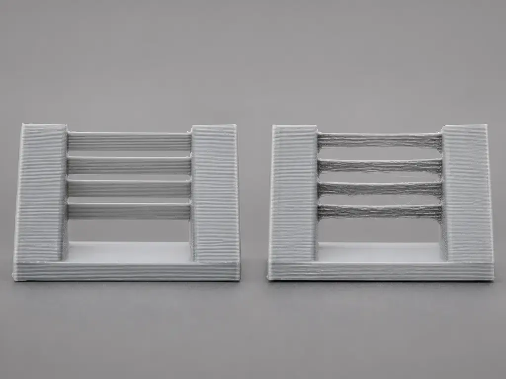
Yes, but not in the same sense as FFF bridge tuning. In SLA, MSLA, and DLP workflows, short unsupported spans can exist, yet the dominant variables are orientation, supports, and the separation or peel forces applied during printing. Formlabs is explicit that supports are central to successful SLA printing and that even self-supporting geometries such as bridges can warp or fail completely without added support. That is why the familiar FFF bridge model of speed, flow ratio, and part-cooling fan does not transfer directly to resin printing. [12]
Formlabs’ Form 2 design-spec examples are useful as process-specific numbers, not as universal resin laws: 3.0 mm maximum unsupported overhang length, 19° minimum unsupported overhang angle from level, and a 21 mm maximum horizontal support span length for a 5 mm wide by 3 mm thick beam, all for Clear Resin at 100 µm. [13]
Design strategies: reduce bridges before you tune harder
Many bridges are created long before the printer moves. Common bridge-producing features include slots, windows, lettering cavities, internal channels, and counterbores that leave a flat ceiling with nothing directly under it. These features may look harmless in CAD, but once sliced they become a span-length problem. If the part must stay one piece in one orientation, tuning may be necessary; otherwise, changing the geometry can remove the bridge before you touch any slicer setting. [6] [11]
Start with orientation, because rotating the part can convert a horizontal ceiling into a vertical wall or a more self-supporting angle. Prusa explicitly recommends changing orientation for difficult bridges. If that is not enough, split the part into two easier bodies, replace flat roofs with chamfers or teardrops, or turn a straight ceiling into an arch. For very local problem areas, Prusa also points to support enforcers or small support islands as a way to break one long bridge into shorter ones. If the part needs tight tolerances or a clean cosmetic underside, supports are not a failure state; they are often the correct design decision. [6] [11]
Troubleshooting: symptom → likely cause → what to test next
The fastest way to improve bridges is to diagnose the defect you can see or measure, not to guess from the whole part. Prusa’s settings-speed-cooling framework is useful because most bridge failures still reduce to one of those three levers. [6]
Before you test anything, confirm that the slicer actually classified the region as a bridge. In Cura 5.12.1, bridge overrides can do nothing if bridge detection is left off, and short features may stay below the documented 5 mm bridge-wall threshold in the base definition. That makes preview inspection part of the experiment, not extra paperwork. [9]
| Symptom | Metric impacted | Likely cause | First variable to test |
|---|---|---|---|
| Midspan droop | Sag depth | Too hot, too much flow, weak cooling, or span too long. | Cooling, then bridge speed. [6] |
| Lines not connecting or visible gaps | Strand separation | Bridge flow too low, or bridge detection never activated. | Verify detection, then bridge flow ratio. [9] [14] |
| Rough underside or roping | Underside quality | Too much heat, too much material, or wet filament. | Dry filament, then lower temperature in small steps. [21] |
| Poor top surface over the bridge | Top-surface closure | Weak support from the bridge layer below. | Bridge speed or bridge density, if exposed. [14] [9] |
| Bridge snaps or delaminates | Structural integrity | Overcooling, weak adhesion, or span beyond the setup. | Reduce cooling aggressiveness or shorten the span. [18] |
| Excess stringing | Visual string count | Hot filament, PETG tendency, or moisture. | Dry filament and reduce temperature carefully. [8] [21] |
Supports are sometimes the right answer. If the part needs predictable underside finish or repeatable geometry beyond what a given printer-material setup can bridge cleanly, a support strategy is often the better engineering choice. [11] [12]
Use the table as a controlled test plan. Change one variable at a time, keep the span geometry constant, and treat the common “drop temperature by 5 °C” advice as a heuristic rather than a standard rule. The same goes for the wet-filament warning: it is a common and useful troubleshooting cue, not proof that moisture is always the cause. [21] [6]
Research snapshot: what studies do and do not tell you
The research picture supports caution, not universals. The 2026 Polymers paper on PLA bridging beams reports that its analytical models matched experiments with coefficients of determination up to R² = 0.9433, and it quantifies buckling behavior by girder width increasing from 1.2 mm to 4.3 mm as span length increases from 60 mm to 140 mm. The same paper also warns that rapid cooling can reduce sagging while weakening adhesion, and its PMC version states that bridging condition in the study was assessed qualitatively through deflection, slope, and delamination defects, with no quantitative mechanical testing performed on the printed parts. The 2021 dimension-error study reaches a similar practical conclusion from another angle: it measured PLA bridges over 25 mm to 43 mm spans and found a limitation range of 33 mm to 37 mm under its own listed conditions, which is useful evidence that bridge limits are real but setup-specific. [18] [19] [20]
How to improve 3D printing bridging
A cautious improvement sequence is usually better than chasing one “best” number. Start by drying the filament if moisture is plausible, return to a known-good baseline profile, verify that your slicer is actually detecting bridges, and then print a bridge test with multiple span lengths. After that, tune one variable at a time: bridge fan behavior, bridge speed, bridge flow ratio, or temperature within the material’s allowed range. Cura users in particular should remember that bridge-specific overrides may do nothing unless detection is enabled and triggered. [21] [6] [9]
For 3D printing bridging, the most reliable rule is not a universal preset but a repeatable test method. The published sources support that narrower conclusion: bridge quality depends on the printer, material, geometry, slicer behavior, and the quality target you are trying to hit. [6] [18] [20]
FAQ
What is bridging in 3D printing?
Bridging is when the printer deposits material across a gap between two supported endpoints instead of laying that strand onto solid material or support structures. In FFF/FDM printing, the first bridge layer is effectively printed over thin air and must stay in shape long enough to support later layers. That makes span length, cooling, and bridge-specific settings important even when the rest of the part prints normally. [6] [1]
Why do my bridges sag in the middle?
Midspan sag usually means the strand stayed soft too long for that span. Common causes are too much heat, too much bridge flow, insufficient cooling, or a span that is simply too long for the setup. Wet filament can also make bridging worse by causing inconsistent extrusion, which is why drying the spool is a sensible early check. If you change temperature, the usual advice is to do it in small 5 °C steps within the material’s recommended range rather than making one large jump. [6] [18] [21]
What are the best bridge printing settings?
There is no universal best bridge preset. In Cura 5.12.1’s base definition, the documented defaults are 15 mm/s bridge-wall speed, 15 mm/s bridge-skin speed, 50% wall flow, 60% skin flow, and 100% fan, but those are software defaults, not promised performance. UltiMaker’s 10 mm guideline and 25 mm Tough PLA example are manufacturer-specific, while Hubs’ over-5 mm rule is a surface-finish threshold for production work. The best practical method is to verify bridge detection, print a bridge test, and tune one variable at a time. [9] [10] [11]
Where are bridging settings in a slicer?
Conceptually, slicers split bridge behavior into two parts: detection and overrides. First, the slicer decides whether a region counts as a bridge. Then it can apply bridge-specific speed, flow, cooling, density, or direction settings if that slicer exposes them. Cura is especially important here because its 5.12.1 base definition documents bridge detection as off by default, so users can change bridge overrides and still see no effect if the feature is not enabled or not triggered by the geometry. [9] [14] [15]
Does PLA or PETG bridge better?
As a qualified tendency, PLA usually bridges more easily than PETG. Prusa explicitly lists PETG as weaker on bridging and overhangs and more prone to stringing, which makes long unsupported spans harder to keep clean. That does not mean PETG cannot bridge; it means the tuning window is often less forgiving, especially when you are trying to balance shape retention against bonding and overall part integrity. A tuned profile still matters as much as the filament family. [8] [6]
Can you bridge with resin printing?
Sometimes, but the logic is different. In resin systems such as SLA, MSLA, and DLP, bridge-like features are mainly controlled by orientation, supports, and peel or separation forces rather than by filament-style bridge speed or bridge flow. Formlabs explicitly warns that even self-supporting bridge-like geometries can warp or fail without support. Its Form 2 examples, such as a 3.0 mm unsupported overhang length and a 21 mm span for a 5 mm × 3 mm beam at 100 µm, are process-specific examples, not general resin laws. [12] [13]
Expert: How do bridge flow ratio overrides differ from global flow/extrusion multiplier?
They affect different scopes. A global flow or extrusion multiplier changes extrusion everywhere, while a bridge flow ratio changes only the toolpaths the slicer has classified as bridge regions. OrcaSlicer makes this distinction explicit by documenting bridge_flow and internal_bridge_flow, with the actual bridge flow derived from that value together with the filament flow ratio and, if present, the object flow ratio. Cura uses different naming, but the same principle applies: bridge-only flow overrides are not the same control as global flow. [14] [9]
Sources
- ISO/ASTM 52900:2021 Additive manufacturing — General principles — Fundamentals and vocabulary
- ASTM F3529-21 Guide for Additive Manufacturing — Design — Material Extrusion of Polymers
- ASTM press release: New Additive Manufacturing Standard Describes Material Extrusion Processes
- Stratasys Legal Information
- NIST Additive Manufacturing Technologies
- Prusa Help: Poor bridging
- Prusa Help: Cooling
- Prusa Help: PETG
- UltiMaker Cura 5.12.1
fdmprinter.def.json - UltiMaker: Design for FDM 3D printing — Maximize your success
- Protolabs Network (Hubs): What are supports in 3D printing? When and why do you need them?
- Formlabs: How supports work in SLA printing
- Formlabs: Design specifications for 3D models (Form 2)
- OrcaSlicer wiki: Bridging
- OrcaSlicer wiki: Strength settings advanced
- SuperSlicer docs: Infill
- Bambu Studio GitHub releases
- He et al., “Investigation on Bridging Defects in 3D-Printed Polylactic Acid Beams Using Fused Filament Fabrication,” Polymers 18(2), 261 (2026)
- PMC full text: “Investigation on Bridging Defects in 3D-Printed Polylactic Acid Beams Using Fused Filament Fabrication”
- “Experimental Study on the Dimension Error of Bridged Structures Printed by Fused Deposition Modeling”
- All3DP: 3D Printing Bridging — 6 Tips for Perfect Bridges