
Summary (Direct answer)
Additive Manufacturing File Format (AMF) is an ISO/ASTM-standardized, XML-based interchange format for additive manufacturing, specified in ISO/ASTM 52915:2020 (AMF Version 1.2, Edition 3). [1] AMF is designed to address STL limitations by representing not only a surface mesh but also materials, color/texture data, metadata, and multi-object placement via constellations. [3] The standard also states that AMF geometry describes only the final target part (not support structures) and does not specify data integrity, electronic signatures, or encryption mechanisms. [2][1]
Historical Background
STL is commonly dated to 1987 and is widely treated as a legacy baseline for representing triangulated surfaces in additive manufacturing workflows. [7][8] Over time, shortcomings identified for STL in additive manufacturing interchange include representing only a surface mesh and lacking provisions for properties such as color, texture, material, and substructure. [3] NIST Technical Note 1823 (2013-11) summarizes similar limitations from a data-exchange perspective, including duplicate information and inconsistencies, poor scaling to high resolution, and lack of support for color, blending materials, and different build orientations, while describing AMF as an XML format intended to replace STL. [4]
AMF progressed through ASTM/ISO standardization in versions that are referenced by ISO/ASTM 52915 editions. ISO/ASTM 52915:2013 is explicitly titled as AMF Version 1.11 and is often cited as an early consolidated specification of the XML data model and its capabilities. [3] The current standard identity is ISO/ASTM 52915:2020-03, “Specification for additive manufacturing file format (AMF) Version 1.2,” Edition 3 (27 pages). [1] In the ISO life-cycle information for ISO/ASTM 52915:2020, the 2016 edition is listed as withdrawn, which is commonly interpreted as a consolidation point for users who need to align implementations to a current ISO/ASTM publication. [1]
Standards and Governance (ISO/ASTM 52915)
ISO/ASTM 52915:2020-03 standardizes AMF Version 1.2 as an XML-based file format intended for standards-compliant interoperability, including strict adherence to an XML schema, and indicates that an AMF XML Schema Definition (XSD) is available from ISO and ASTM. [1] Within its stated scope boundaries, the same standard explicitly excludes specifying mechanisms for data integrity, electronic signatures, or encryption, which affects how AMF is used in regulated or security-sensitive “digital thread” scenarios where separate controls are required. [1]
File Encoding and Container Considerations
AMF is specified as XML 1.0, and the ISO/ASTM 52915:2020 sample text states that only UTF-8 and UTF-16 should be specified for encoding; unrecognized encodings should cause the file to fail to load. [2] In practice, these constraints motivate implementers to validate the XML declaration early, enforce encoding allow-lists, and ensure that exporters consistently emit UTF-8 or UTF-16 when generating an “XML 3D file” intended to be broadly portable across toolchains. [2]
While the AMF specification is separate from general-purpose archival standards, ISO/ASTM 52915:2013 includes the ZIP File Format Specification (PKWARE) in its references, and AMF is often discussed in workflows where files may be compressed as an archive for storage or transfer. [3] This reference supports the existence of ZIP-aware handling patterns, but compression is best treated as an implementation and pipeline decision rather than a guarantee that every AMF consumer accepts a compressed container in the same way. [3]
Core Data Model (AMF’s five top-level elements)
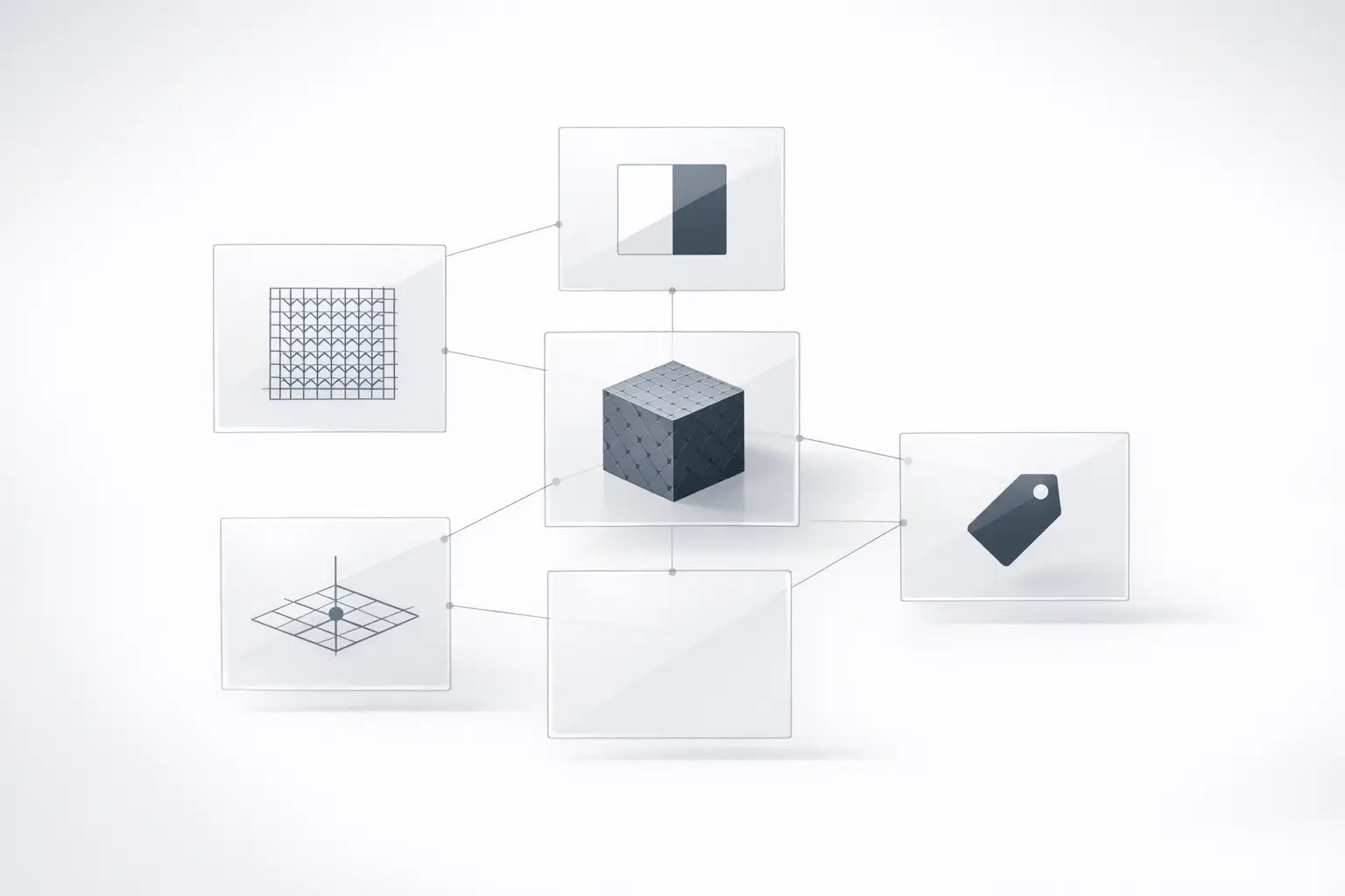
AMF structures data around five top-level elements: <object>, <material>, <texture>, <constellation>, and <metadata>. [2] A common conceptual mapping is that an <object> defines geometry (typically as a mesh of vertices and triangles) and may reference materials; <material> defines material identifiers and properties for reuse; <texture> carries texture definitions used for texture mapping; <constellation> defines hierarchical placement patterns of objects (and other constellations); and <metadata> attaches name/value-style information at file or object scope, which NIST (2015-08) describes as supported at file or object scope in AMF’s XSD-defined structure. [2][5]
Geometry Representation (Mesh, vertices, triangles)
AMF geometry is typically expressed as a triangle mesh defined by a vertex list and triangle indices. In the ISO/ASTM 52915:2020 sample, vertices are implicitly assigned integer IDs starting at zero and increasing monotonically, and each triangle references three vertices via <v1>, <v2>, and <v3>. [2] The same sample specifies that vertex order follows the right-hand rule and is counter-clockwise when viewed from outside the volume, making triangle winding a normative interoperability point for importers that infer surface orientation from index order. [2]
Although AMF is used to convey part geometry to a slicer, the 2020 sample includes a design boundary that the geometry “shall not be used to describe support structure,” and that only the final target structure shall be described. [2] This boundary distinguishes AMF part definition from process- or machine-specific build instructions, and it affects how engineers model auxiliary features that may be generated downstream (for example, automatically generated supports or orientation-dependent structures). [2]
Advanced Representation Features (What AMF adds beyond STL)
ISO/ASTM 52915:2013 frames AMF’s motivation partly as addressing STL limitations by adding representational capacity for properties beyond a surface mesh, including color, texture, material, and substructure. [3] AMF therefore commonly appears in discussions of multi-material and graded materials representation, while still remaining an interchange format rather than a printer control language. [4] A minimal, writer-authored schematic example (abridged) illustrating element nesting and IDs is shown below (IDs and content are illustrative, not normative):
Curved triangles and smooth geometry
ISO/ASTM 52915:2013 specifies optional curved triangles/edges and describes a reader behavior in which curved triangles are recursively subdivided during read; it recommends a minimal recursion level of 4, converting 1 curved triangle into 256 flat triangles. [3] This mechanism is a representation feature aimed at compactly encoding smooth surfaces for later tessellation, but it does not by itself guarantee a specific printed surface finish, since downstream tessellation, slicing settings, and the process physics govern realized surface quality. [3]
Materials and material IDs
AMF includes a top-level <material> element as part of its core model, enabling explicit material identifiers that can be referenced by other elements. [2] NIST Technical Note 1823 characterizes AMF’s design intent as supporting material blending (among other shortcomings of STL) in an XML representation, which is often discussed in relation to multi-material and graded materials workflows where part regions may differ in assigned material definitions. [4] The practical degree of interoperability depends on whether exporters, slicers, and printers agree on the subset of material semantics they interpret from the schema-conformant file. [1][4]
Color and texture mapping
ISO/ASTM 52915:2013 defines color using RGBA, including an explicit transparency channel <a> where 0 denotes zero transparency and 1 denotes full transparency; values below 0 clamp to 0 and above 1 clamp to 1. [3] The same edition describes texture maps as 2D or 3D and encodes texture data as Base64-encoded bytes interpreted as grayscale values in the 0–255 range, which can be used for texture mapping but implies that some texture payloads are expressed as grayscale intensity rather than full-color raster imagery. [3]
Constellations (object patterns)
ISO/ASTM 52915:2013 describes a <constellation> element that hierarchically combines objects and other constellations into a relative pattern for printing, which can be used to define repeated instances and placements. [3] The same text states that if no constellation is specified, objects import with no relative position data, meaning that a consumer may treat multiple objects as unpositioned and rely on downstream placement (for example, in a slicer) for build layout. [3]
Metadata
ISO/ASTM 52915:2013 provides examples of metadata vocabulary terms such as cad, revision, tolerance, volume, elastomodulus, and poissonratio, illustrating that AMF metadata can carry engineering-relevant attributes beyond geometry. [3] NIST (2015-08) additionally summarizes AMF as supporting metadata at file or object scope within an XSD-defined structure, which is often used to connect AMF exports to broader traceability efforts in model-based engineering and the digital thread. [5]
Interoperability and Workflow Position (Design data vs build data)
AMF is typically positioned between CAD/export and slicing/printing as a standards-oriented interchange artifact: design tools export an XML 1.0 file, validators and viewers can perform schema checks against the XSD schema, and slicers then interpret geometry and attributes to generate build-specific toolpaths. [1][2] The encoding constraint that only UTF-8 and UTF-16 should be specified (with unrecognized encodings causing load failure) is an interoperability lever, since it constrains importers to a small set of encodings and encourages deterministic parser behavior across platforms. [2]
AMF also formalizes unit expression: the unit attribute may be millimetre, inch, foot, metre, or micron units (micron), defaulting to millimetres if omitted. [2] This explicit unit mechanism can reduce ambiguity when transferring mesh coordinates between tools, but it remains distinct from build instruction data, and the 2020 sample explicitly forbids encoding support-structure geometry as part geometry. [2] NIST (2013-11) characterizes AMF as an exchange format intended to address STL shortcomings, reinforcing that its primary role is design-data interchange rather than machine control. [4]
Comparison: AMF vs STL vs 3MF (Mandated table)
AMF, STL, and 3MF occupy overlapping but distinct niches in additive manufacturing data exchange: STL remains a historically entrenched triangle-mesh interchange with a 1987 origin, while AMF is a formal ISO/ASTM XML schema-based specification (with explicit scope boundaries on security mechanisms), and 3MF is commonly treated in modern software ecosystems as a standardized package-based alternative that a consortium states was recognized in 2025 as ISO/IEC 25422:2025. [7][1][6]
| Attribute | AMF | STL | 3MF |
|---|---|---|---|
| Standards body / status | ISO/ASTM 52915:2020 (AMF 1.2). [1] | Legacy format attributed to 3D Systems (1987 origin often cited). [7] | Consortium states ISO/IEC 25422:2025 recognition. [6] |
| Encoding / container | XML-based; strict schema posture (XSD available). [1] | Typically a triangle mesh representation. [7] | Consortium-positioned as a packaged format standardized in 2025. [6] |
| Units | Unit attribute may be millimetre, inch, foot, metre, or micron; default millimetres. [2] | Unit handling is commonly workflow-dependent (not addressed here). | Not addressed here. |
| Color / textures | RGBA defined (alpha semantics in 2013); textures can be Base64 grayscale 0–255. [3] | STL limitations described as lacking color/texture/material/substructure provisions. [3] | Not addressed here. |
| Multi-object placement | <constellation> defines hierarchical relative patterns; absent constellation implies no relative position data. [3] |
Not addressed here. | Not addressed here. |
| Security mechanisms specified | Does not specify integrity, signatures, or encryption. [1] | Not addressed here. | Not addressed here. |
| Typical role in pipeline | Interchange from design to slicer with materials/textures/metadata; not a support-geometry or build-instruction file. [2] | Mesh interchange baseline. [7] | Common modern interchange package per consortium positioning. [6] |
Implementation Notes and Common Pitfalls (List-driven)
AMF implementations often succeed or fail on small compliance details: the XML declaration and encoding allow-list, unit defaults, vertex indexing and winding, and whether files are treated as plain XML or moved through a compressed archive step in a pipeline. [2][3] Geometry import errors can arise from violating implicit vertex ID assumptions (starting at 0 and increasing monotonically), from inconsistent right-hand-rule triangle winding, or from attempting to embed auxiliary geometry such as supports even though the 2020 sample forbids using AMF geometry to describe support structure. [2] Texture interoperability can also be limited when consumers assume full-color raster textures but encounter Base64-encoded grayscale 0–255 payloads as described in ISO/ASTM 52915:2013. [3]
AMF features explicitly evidenced in ISO/ASTM 52915 clauses
- Units: unit may be millimetre, inch, foot, metre, or micron; default is millimetres if omitted. [2]
- XML 1.0 encoding constraints: only UTF-8 and UTF-16 should be specified; unknown encodings should fail to load. [2]
- Five top-level elements:
<object>,<material>,<texture>,<constellation>,<metadata>. [2] - Curved triangles: optional; recommended minimal recursion level 4, where 1 curved triangle becomes 256 flat triangles during read. [3]
- RGBA alpha semantics:
<a>uses 0 for zero transparency and 1 for full transparency; values clamp to [0,1]. [3] - Textures: 2D or 3D; Base64-encoded bytes as grayscale values in the 0–255 range. [3]
- Constellation concept: hierarchical combination of objects/constellations into relative patterns; absent constellation implies no relative position data. [3]
- Metadata vocabulary examples: cad, revision, tolerance, volume, elastomodulus, poissonratio. [3]
A practical validation approach is to treat AMF as “schema-first” XML exchange and implement deterministic failure modes for non-conformant inputs, especially for encoding handling and geometry conventions that downstream slicers may assume. [1][2] When interchanging between tool vendors, it is also common to document which optional features (for example, textures, curved triangles, or specific metadata keys) are expected to round-trip, since the standard’s representational capability does not imply universal slicer support for every feature. [3]
Validation checklist for AMF exporters/importers
- Verify XML 1.0 declaration and allowed encoding (UTF-8 or UTF-16). [2]
- Confirm unit attribute handling and default behavior (default millimetres when omitted; support micron units if claimed). [2]
- Validate vertex indexing (implicit IDs from 0, monotonic) and triangle winding (right-hand rule, CCW from outside). [2]
- Reject or flag unsupported encodings so that unrecognized encodings fail to load. [2]
- Ensure no support-structure geometry is encoded as part geometry (final target structure only). [2]
- Confirm texture payload and pixel range assumptions (Base64 grayscale, 0–255) before applying texture mapping. [3]
Adoption Signals and Ecosystem Notes (Non-exhaustive, sourced)
Public statements provide limited but concrete signals of ecosystem support: Sculpteo’s glossary states it has supported AMF since 2011 (as one service-bureau example, without implying universal adoption). [9] Separately, the 3MF Consortium site states that in 2025 the .3MF format and extensions were recognized as an international standard under ISO/IEC 25422:2025, which is often cited when explaining why 3MF is treated as a modern standardized alternative in many software ecosystems. [6]
FAQ
What is an AMF 3D file (Additive Manufacturing File Format) and what standard defines it?
An AMF 3D file is an XML-based additive manufacturing interchange file standardized as ISO/ASTM 52915:2020-03, “Specification for additive manufacturing file format (AMF) Version 1.2,” Edition 3. [1] The ISO abstract positions AMF’s strict adherence to an XML schema (XSD available from ISO and ASTM) as a mechanism supporting standards-compliant interoperability. [1]
How does the AMF additive manufacturing format handle units compared with STL?
In the ISO/ASTM 52915:2020 sample, AMF provides an explicit unit attribute that may be millimetre, inch, foot, metre, or micron, and defaults to millimetres if omitted. [2] The same defaulting behavior and unit vocabulary are also described in ISO/ASTM 52915:2013, indicating that explicit unit handling is a longstanding part of AMF rather than a new addition in 2020. [3]
Does an XML 3D file in AMF support color and textures — and how is transparency defined?
ISO/ASTM 52915:2013 defines color in AMF using RGBA, including transparency via <a> where 0 represents zero transparency and 1 represents full transparency, with values clamped into the [0,1] range. [3] The same document describes texture maps as 2D or 3D and encodes texture payloads as Base64-encoded bytes interpreted as grayscale values from 0 to 255. [3]
Expert — What are “curved triangles” in AMF, and what is the recommended subdivision behavior?
ISO/ASTM 52915:2013 describes curved triangles/edges as an optional representation; when read, curved triangles are recursively subdivided, and a minimal recursion level of 4 is recommended, converting 1 curved triangle into 256 flat triangles. [3] This recommendation describes parser tessellation behavior rather than guaranteeing that downstream manufacturing will produce a correspondingly smooth surface. [3]
Expert — What does AMF’s “constellation” element do in multi-part builds?
ISO/ASTM 52915:2013 describes <constellation> as a hierarchical mechanism that combines objects and other constellations into a relative pattern for printing, supporting repeated instances and placement definitions. [3] It also states that when no constellation is specified, objects import with no relative position data, leaving placement to downstream tools such as a slicer. [3]
AMF vs 3MF vs STL — which format is standardized today and what are the security boundaries?
AMF is standardized under ISO/ASTM 52915:2020, while STL is commonly dated to 1987 and is widely treated as a legacy interchange format. [1][7] The 3MF Consortium site states that in 2025 the .3MF format and extensions were recognized as an international standard under ISO/IEC 25422:2025. [6] For security boundaries, ISO/ASTM 52915:2020 explicitly states it does not specify mechanisms for data integrity, electronic signatures, or encryption. [1]
Sources
- ISO/ASTM 52915:2020 — Specification for additive manufacturing file format (AMF) Version 1.2 (ISO page)
- ISO-ASTM-52915-2020 sample PDF (encoding, units, geometry, elements)
- ISO/ASTM 52915:2013 — Additive manufacturing file format (AMF) Version 1.11 (PDF)
- NIST Technical Note 1823 (2013) — AMF intent and STL shortcomings summary (PDF)
- NIST (2015) SFF Symposium proceedings paper — AMF governance, XSD, metadata scope (PDF)
- 3MF Consortium — statement of ISO/IEC 25422:2025 recognition (site)
- Wikipedia — STL (file format) (1987 origin claim)
- Rathod (2017) thesis PDF — STL historical attribution (secondary academic source)
- Sculpteo glossary — AMF definition (states AMF support since 2011)