
Summary
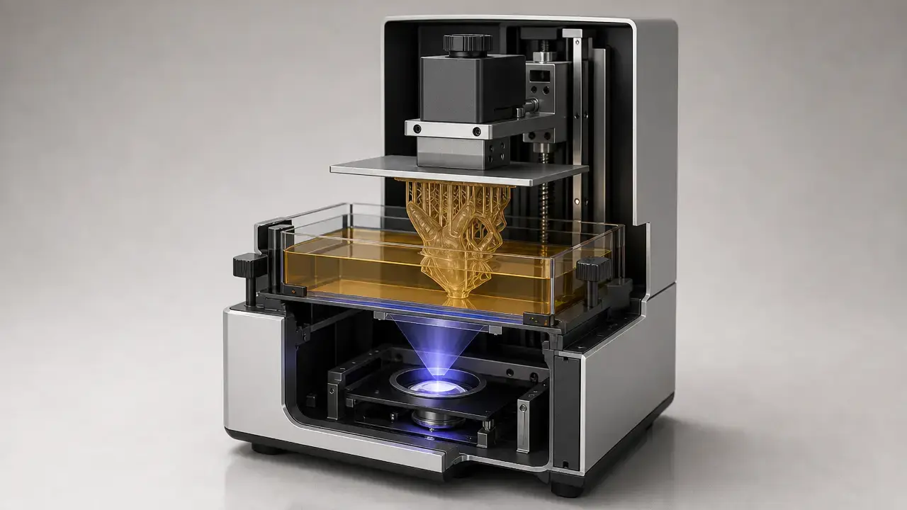
Vat photopolymerization is an additive manufacturing process in which a liquid photopolymer in a vat is selectively cured by light-activated polymerization. [2] In practice, the family includes SLA, DLP, and LCD/MSLA resin printing, but the process label is broader than any one machine style. [1] [2]
That distinction matters because SLA, DLP, and LCD/MSLA do not pattern light the same way, and those differences affect scaling behavior, optical efficiency, maintenance, and failure modes. It also matters for measurement: ISO/ASTM 52902 treats geometric capability as something assessed with test artefacts, not reduced to a single brochure number, while NIST has shown that cure-related working-curve values can vary widely across laboratories. [3] [6] The workflow matters too, because resin printing does not end when the build finishes; washing, drying, post-curing, and finishing all affect the final result. Safety runs through the whole process, from uncured resin handling to solvents, UV exposure, and ventilation. [20] [21] [22]
Key Terms and Metrics
This article uses current standards vocabulary where possible. ISO/ASTM 52900:2021, Edition 2, was published in November 2021 and confirmed by ISO in August 2025 as remaining current. [1] Accuracy language also needs discipline: ISO 5725-1 distinguishes trueness and precision rather than treating “accuracy” as a loose synonym for fine detail. [5]
- VPP / vat photopolymerization: an additive manufacturing process in which liquid photopolymer in a vat is selectively cured by light-activated polymerization. [2]
- Resin 3D printing: a broad market label for photopolymer-based printing; in this article it usually means VPP unless a different process is named.
- SLA: stereolithography; here, laser-scanned stereolithography.
- DLP: digital light processing; usually projector-based image formation using a DMD. [10]
- LCD/MSLA: masked stereolithography using an LCD mask with a near-UV backlight. [10]
- Material jetting: a different AM family in which droplets of feedstock material are selectively deposited; photopolymer resin can be used there too, so not all photopolymer printing is VPP. [2]
- Layer height: the planned Z-step thickness in slicing; a process setting, not a direct measurement of dimensional accuracy.
- Accuracy vs precision: precision is closeness among repeated results, while trueness concerns closeness to a reference value; “accuracy” depends on both being controlled. [5]
What “Vat Photopolymerization” Means (and What It Doesn’t)
Vat photopolymerization, or VPP, is the standards term for an additive manufacturing process in which a liquid photopolymer in a vat is selectively cured by light-activated polymerization. [2] That defines a process category, not a brand, not a single printer layout, and not a synonym for every machine that uses resin. This article follows current ISO/ASTM vocabulary so comparisons stay consistent across machine types and materials. [1]
The boundary matters most when people say “resin printer.” The phrase is useful in ordinary conversation, but it is broader and less precise than VPP. Material jetting, for example, can also use photopolymer resin, yet ISO/ASTM 52900 classifies it separately because the process is based on selective droplet deposition rather than curing selected regions of a resin vat. [2] Similar chemistry does not make the process category the same.
Naming also gets blurred in product listings and forum discussions. In this article, SLA is reserved for laser-scanned stereolithography, DLP for projector-based image formation, and LCD/MSLA for masked systems that use an LCD and backlight. That stricter taxonomy helps because the optical path, scaling behavior, and maintenance tradeoffs are not identical even when all three belong to the same VPP family. [10]
How Vat Photopolymerization Works
A VPP resin is usually formulated from monomers or oligomers, photoinitiators, and additives that tune properties such as viscosity, color, shrinkage behavior, stiffness, toughness, or thermal response. When the appropriate wavelength reaches the resin, the photoinitiator generates reactive species that start polymer growth and crosslinking. The part solidifies where the delivered light dose is high enough, but the cured shape is determined by more than chemistry alone. Optics, exposure control, resin flow, and the mechanics of layer support or separation all influence the final outcome. [13]
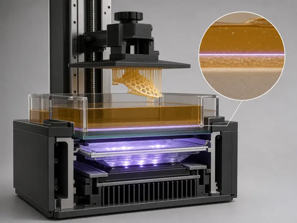
Several effects complicate that curing zone. Oxygen can inhibit photopolymerization near an exposed interface, which is one reason continuous and high-speed VPP variants pay close attention to interface chemistry rather than just adding more light. [12] [13] Absorbers, pigments, and fillers also change the result because they alter penetration depth, scattering, and edge fidelity. In LCD/MSLA systems, the optical stack becomes part of the story: LCD-based masking approaches use a near-UV backlight, and components such as color filters and polarizers affect transmission efficiency and usable wavelengths. [10]
That is why layer height should not be confused with cure depth. Layer height is the planned Z increment chosen in software. Cure depth is the actual depth of polymerization under a given exposure condition. They are related, but they are not the same measurement. NIST’s interlaboratory working-curve study showed that the common working-curve parameters Dp and Ec varied so widely across participants that they should be treated as process-specific measurements rather than universal material constants. [6] [7]
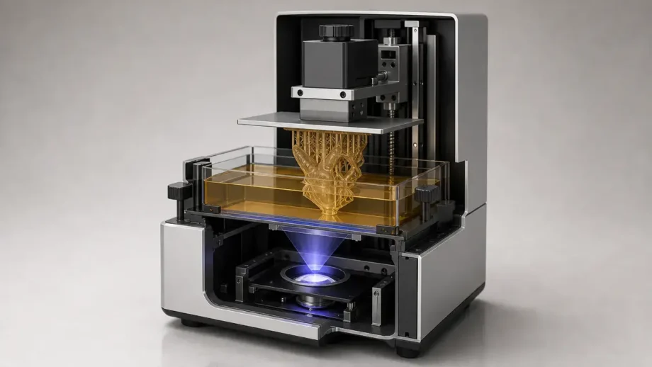
At the hardware level, a VPP printer typically combines a resin vat, a light engine, a build platform, and Z-axis motion. Many bottom-up desktop systems also use a transparent interface or flexible vat film at the bottom of the tank, but the exact film or membrane is not universal across the category. The practical point is that vat photopolymerization depends on the whole optical, chemical, and mechanical system working together, not on the light source alone. [11] [13]
Top-Down vs Bottom-Up VPP Architectures
VPP systems are commonly divided into top-down and bottom-up architectures. In a top-down system, curing occurs near the free surface of the resin, with the light source positioned above the vat. In a bottom-up system, the part is built from an inverted platform and each layer cures against a constrained interface at the bottom of the vat. Reviews of VPP architecture treat this as a real process fork rather than a minor implementation detail, because light-source position and recoating behavior change the mechanics of the print cycle. [11]
That split changes the tradeoffs. Top-down systems typically require more resin in the tank and handle recoating differently, while bottom-up systems can use less resin but must repeatedly separate the cured layer from the vat interface. Separation from that constrained surface is a major challenge in bottom-up VPP and interacts directly with speed, failure risk, and surface quality. Incomplete release, delamination, suction-related stress, and refill problems are therefore much more central to bottom-up discussions than to top-down ones. [11] [13]
Resin 3D Printing Process Workflow
The resin 3D printing process starts well before exposure begins. A slicer converts the 3D model into layers, generates supports where needed, and assigns exposure settings suited to the chosen resin and layer height. During printing, the machine exposes a layer, moves in Z, and allows resin to refill or recoat before the next cycle. Exposure time is only one part of the timing picture; total cycle time also depends on lift or tilt motion, separation behavior, resin recovery, and any pauses built into the machine. A desktop MSLA example from Prusa lists layer exposure times of 1.3–2.4 seconds depending on material and layer height, which shows why exposure values are not portable across printers or resins. [16]
Post-processing is part of the process, not an optional add-on. A freshly printed part typically still carries uncured resin on its surface and may not yet have reached its final material state. Washing removes surface resin, drying removes solvent, post-curing can complete or stabilize the polymer network, and finishing comes afterward. Formlabs presents one vendor-specific baseline in its SLA finishing guide: for many resins in the Finish Kit workflow it recommends two 10-minute soaks in separate baths with 30 seconds of manual movement, followed by at least 30 minutes of drying when volatile solvents such as IPA are used before post-curing or post-processing. That is an example workflow, not a universal rule. [20]
- Prepare the model. Orient the part, add supports, and choose a layer height and exposure profile suited to the resin.
- Slice the geometry. Convert the model into layer data and machine instructions.
- Load resin and inspect the vat. Confirm that the vat, interface, and build platform are clean and ready.
- Expose each layer. Cure the first layers with settings intended to anchor the part, then continue with normal layer exposures.
- Move the Z axis. Create space for the next layer to form.
- Separate, recoat, or refill. In bottom-up systems, detach the cured layer from the vat interface and let resin flow back into place.
- Remove the part. Take the build from the platform when printing is complete.
- Wash away uncured resin. Use the resin maker’s or machine maker’s recommended solvent workflow. [20]
- Dry, post-cure, then finish. After drying and any required post-cure, remove supports and perform sanding, polishing, or inspection as needed. [20]
SLA vs DLP vs LCD/MSLA: Same VPP Family, Different Light Patterning
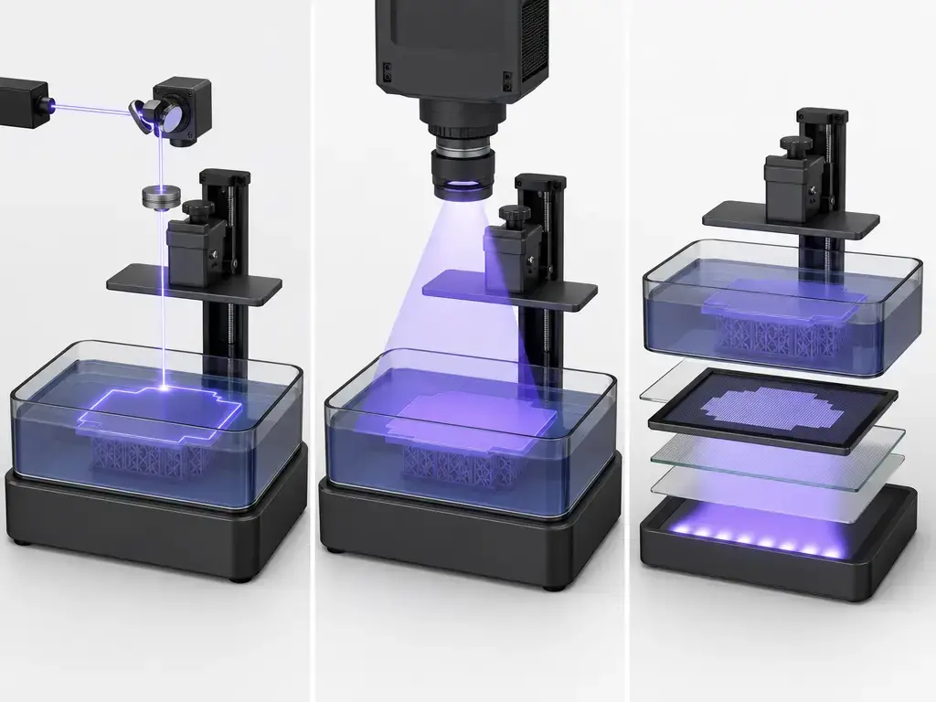
SLA uses a scanned laser spot to trace each layer, so exposure is serial rather than whole-layer. That makes throughput depend not only on resin response but also on beam size, scan strategy, and the area that must be written. Manufacturer-reported industrial examples therefore tend to describe a combination of build envelope, laser wavelength, and beam range rather than a single pixel-style number. A recent 3D Systems brochure for the SLA 750 lists a 750 × 750 × 550 mm maximum part size, a 355 nm laser, and a dynamic beam size of 125–1000 µm, while also stating that accuracy may vary with build parameters, geometry, orientation, and post-processing. [18]
DLP and LCD/MSLA can both expose an entire layer at once, but they do not create that image the same way. DLP uses projector-based imaging with a digital micromirror device, while LCD/MSLA uses an LCD mask with a near-UV backlight and an optical stack that imposes transmission limits. [10] That difference is why SLA vs DLP vs LCD printing is not just a matter of “laser versus pixels.” Even among whole-layer systems, the optical path changes light efficiency, field uniformity, scaling constraints, and usable wavelengths. [10]
The tradeoffs do not form a simple performance ladder. Laser SLA scales differently because the beam is written sequentially. DLP can deliver fast layer exposures, but field size and projection optics shape how that speed translates across the build plane. LCD/MSLA can be compact and effective, especially in desktop systems, but the mask stack itself costs light. The useful comparison is not “which one has the highest resolution,” but which exposure method, resin, and workflow match the job. [10] [18] [19]
| Process | Light-patterning method | Metric to watch | Main limitation |
|---|---|---|---|
| SLA | Scanned laser spot traces the layer. | Beam size and build envelope. Manufacturer example: SLA 750, 750 × 750 × 550 mm, 355 nm, 125–1000 µm beam. [18] | Serial exposure makes large-area coverage slower. |
| DLP | Projector-based image formation with a DMD. | Field of view and projected pixel size. Manufacturer example: Figure 4 135, 135 × 76 × 165 mm, 405 nm, 50 µm pixel, 20/30/50 µm standard layers, up to 70 mm/h for most materials. [19] | Projection optics and field scaling constrain coverage. |
| LCD/MSLA | LCD mask with near-UV backlight. | Transmission efficiency, cure-plane irradiance, and masked pixel pitch. Manufacturer example: Form 4, 405 nm, 16 mW/cm² at the cure plane, 50 µm pixel size, 20.0 × 12.5 × 21.0 cm build volume, maximum 100 mm/h, typical average 40 mm/h. [15] | The LCD optical stack reduces light transmission and wavelength flexibility. [10] |
| Continuous variants | Projection or scanning with a moving interface. | Interface control and interlayer continuity. [12] [13] | Interface chemistry and constrained-surface mechanics still limit the process. [13] |
| Two-photon | Focused laser induces highly localized polymerization. | Minimum feature size. | Extremely small write volume and high system complexity. |
A second manufacturer-reported desktop LCD/MSLA example makes the same point another way: Prusa lists 1.3–2.4 second exposure time depending on material and layer height for the SL1S, so a time number from one machine should not be treated as a general property of VPP. [16]
Continuous / “High-Speed” Variants
Continuous and high-speed approaches still sit within the broader VPP family, but they change how the interface behaves during printing. In the CLIP approach described by Tumbleston and coauthors, an oxygen-permeable window below the projection plane creates a thin “dead zone” where photopolymerization is inhibited, allowing continuous part movement instead of a strict stop-and-separate cycle for every layer. [12] That can improve speed, but it does not erase the category’s underlying constraints: interface control, resin behavior, heat management, and separation-related mechanics still matter. [13]
Performance Metrics: Resolution vs Accuracy vs Repeatability vs Speed
“Resolution” is one of the least disciplined words in resin printing. Depending on context, it might refer to masked pixel pitch, projected pixel size, laser spot size, minimum visible surface texture, or even layer height. That is why accuracy terminology needs to stay anchored to measurement science rather than marketing shorthand. ISO 5725-1 distinguishes trueness and precision, and treats accuracy as meaningful only when the measurement process is under control. A small pixel or fine beam can coexist with dimensional bias, while a machine can repeat the same wrong result very consistently. [5]
That measurement framing is built into AM standards. ISO/ASTM 52902:2023 is specifically about geometric capability assessment using test artefacts and measured quantities; it supports capability evaluation and calibration, and it prescribes what should be measured without dictating one universal measurement method. [3] NIST’s additive manufacturing test artifact work makes the same point from an independent metrology perspective: measured errors on an artifact can be linked back to specific sources in the AM system rather than left as vague brochure claims. [8] NIST’s program page also describes a repeatable workflow focused on geometric accuracy and surface roughness, including periodic rechecks after maintenance or recalibration. [9]
Working-curve values are another place where shorthand fails. In NIST’s interlaboratory study, 24 laboratories submitted 35 datasets for a single-batch resin, yet measured Dp varied by as much as 7× and Ec by as much as 70×. [6] [7] That does not make the concepts useless; it means those values depend strongly on setup, optics, method, and interpretation. They are measurements inside a process context, not plug-and-play constants.
| Metric | What it actually measures | What it does NOT guarantee | What influences it |
|---|---|---|---|
| Pixel size / pitch | The lateral sampling grid for masked-image systems. | Final dimensional accuracy or perfectly sharp edges. | Optical blur, transmission losses, resin scatter, exposure dose, and anti-aliasing strategy. |
| Laser spot size | The effective beam diameter used to write features in laser SLA. | Equal detail everywhere in the build volume. | Beam quality, focus, scan speed, path planning, and resin response. |
| Layer height | The planned thickness increment between slices. | That the cured layer exactly matches the nominal Z increment. | Z mechanics, cure depth, resin flow, and interlayer bonding behavior. |
| Cure depth (Dp / Ec) | How a resin responds to light exposure under a stated setup. | Transferability across machines, wavelengths, or labs. [6] | Resin chemistry, optics, irradiance, wavelength, and test method. |
| Minimum feature size | The smallest detail that can be formed reliably under stated conditions. | Functional fit, clearance, or robustness in arbitrary geometry. | Orientation, bleed, support strategy, wash, post-cure, and part shape. |
| Dimensional accuracy | Closeness of the printed part to the target model. | Low variation from part to part. | Calibration, shrinkage, compensation strategy, geometry, and measurement method. |
| Repeatability / precision | Closeness among repeated builds or repeated measurements. [5] | Correctness relative to nominal dimensions. | Machine stability, resin lot, environment, handling, and metrology practice. |
| Surface finish | Surface texture and visible layer or exposure artefacts. | Internal accuracy or watertightness. | Layer height, peel dynamics, resin flow, exposure control, and finishing steps. |
| Print speed | Time to complete a part, layer set, or build under a stated setup. | Comparable productivity across different printers or jobs. | Exposure method, part area, separation mechanics, refill behavior, and post-processing assumptions. |
For practical comparison, the useful question is not “Which machine advertises the smallest number?” but “What was measured, with what artifact, by what method, and under what resin and post-processing conditions?” ISO/ASTM 52902 and the NIST artifact framework point to the same answer: measure the printed result, not just the printer specification. [3] [8] [9]
Vat Photopolymerization Materials
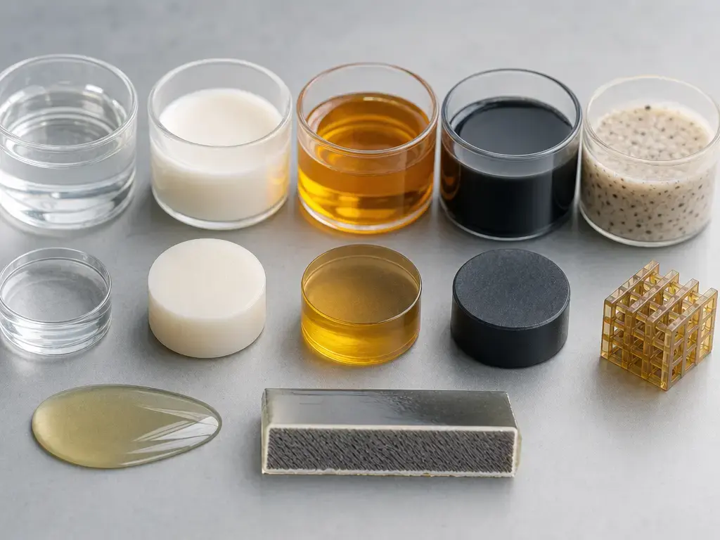
The main vat photopolymerization materials are photopolymer resins formulated for different use cases rather than one generic “resin” behavior. Common categories include general-purpose resins for prototyping, tougher grades for handling or snap-fit testing, rigid systems for stiffer parts, flexible or elastomer-like systems for compliant components, castable formulations for investment-casting patterns, clear resins for visual or fluidic use cases, and higher-temperature materials for parts that must tolerate more heat. Some certified medical or dental workflows also exist, but suitability depends on the exact material, printer, post-processing workflow, and intended use rather than the label alone.
The important caveat is that final properties do not come from chemistry alone. They depend on resin formulation plus geometry, build orientation, support strategy, wash conditions, drying, post-cure schedule, and the test method used to judge the part. That is one reason material datasheets and printed-part performance should not be treated as interchangeable ideas.
Ceramic-filled systems are a distinct branch of VPP rather than a simple extension of neat polymer resins. ISO/ASTM 52940:2025 defines characterization categories for ceramic slurry feedstocks in VPP, including solids content, dynamic viscosity, particle size distribution, chemical composition, and dispersion stability. [4] Those categories matter because ceramic slurries change flow, scattering, sedimentation risk, and cure behavior. The downstream process chain also changes. A recent review describes ceramic resin preparation followed by vat photopolymerization, debinding, and sintering, which means the printed object is a green body rather than the final ceramic component. [14]
- Standard resins: general prototyping, concept models, and fit checks.
- Tough resins: parts that need more resistance to cracking or handling damage.
- Rigid or engineering resins: jigs, housings, fixtures, and stiffer functional parts.
- Flexible and elastomer-like resins: grips, compliant mechanisms, seals, and bendable parts.
- Clear resins: visual flow paths, transparent sections, and display parts where transparency matters.
- High-temperature resins: parts that must tolerate elevated thermal exposure.
- Castable resins: investment-casting patterns intended to burn out cleanly.
- Biocompatible or medical-adjacent resins: specialized workflows where application-specific validation matters.
- Ceramic slurries: particle-filled VPP feedstocks that require debinding and sintering after printing. [4] [14]
Applications
Vat photopolymerization is most useful where fine detail, smooth surfaces, or controlled layer formation matter more than the raw throughput advantages of other AM families. Common uses include appearance prototypes, fit-check parts, jigs and fixtures, casting patterns, and dental models. In these contexts, users often care less about headline build speed than about repeatable geometry, clean surface quality, and access to material classes tailored to the job.
More specialized applications extend the same process family into different territory. Microfluidic components and optical or light-guiding parts benefit from surface quality and precise light-patterning control. Ceramic parts are an important special case because VPP produces a green body that still needs debinding and sintering before it becomes a finished ceramic component. [14] Conductive or sensing parts also exist, but those are better treated as research or niche-production outputs than mainstream defaults.
- Appearance prototypes and display models.
- Fit-check parts and assembly aids.
- Jigs, fixtures, and workholding tools.
- Investment-casting patterns.
- Dental models and study models.
- Microfluidic devices.
- Optical or light-guiding components.
- Ceramic green bodies for later debinding and sintering. [14]
- Specialized research parts, including conductive or sensing structures.
Limitations, Failure Modes, and Safety
The process has recurring technical limits even before safety is considered. Bottom-up systems are especially sensitive to separation at the vat interface, and that challenge interacts directly with speed. Overexposure can round corners, thicken walls, or close fine gaps, while underexposure can weaken layers or leave small details incomplete. Support design and orientation also matter because they influence distortion during printing, washing, and post-curing. Shrinkage and warp can appear as the network forms and then continues to change after printing. [13]
Uncured resin handling should be treated as chemical handling, not routine cleanup. UL 200B recommends chemical-resistant gloves such as nitrile or neoprene for vat photopolymerization and specifically says not to use latex gloves when handling uncured resins. It also recommends safety glasses or goggles with UV-protection features. [22] In practice, that means treating contaminated tools, resin-coated parts, and bench surfaces as exposure points until the part has been washed and the workspace has been cleaned.
Solvents add a second hazard layer. IPA and similar wash solvents can be flammable, can retain dissolved uncured resin, and can leave parts needing a drying interval before post-curing. Formlabs’ support guidance gives one clear example: when volatile solvents such as IPA are used, parts should dry for at least 30 minutes before post-curing or post-processing. [20] That timing should be read as a vendor example, not a universal number for every resin or solvent.
UV and ventilation need separate attention. Post-cure equipment is meant to deliver controlled exposure to the part, not open exposure to the operator. NIOSH’s 2024 bulletin on safe 3D printing also frames the broader emissions picture around VOCs, semi-VOCs, and ultrafine particles, and it presents vat polymerization as a process that cures photopolymer resin using UV light from a laser or projector. [21] The practical message is to use guarding, follow the safety data sheet and machine instructions, and rely first on source control and ventilation rather than on gloves alone. [21] [22]
- Wear chemical-resistant gloves suitable for uncured resin handling, and avoid latex for that task. [22]
- Use eye protection appropriate to the workflow, including UV-protective eyewear where required. [22]
- Keep printing, washing, and post-curing areas ventilated according to the equipment and solvent guidance. [20] [21]
- Clean spills promptly and treat contaminated tools and wipes as resin-bearing waste.
- Keep the resin SDS and printer-specific instructions available at the point of use.
- Store wash solvents away from ignition sources and manage used solvent as contaminated waste. [20]
- Dispose of resin waste, wipes, and spent solvent according to local rules and site procedures.
Current Research, Market Context, and Practical Takeaways
Current research in VPP is moving toward better materials, tighter process control, and more functional parts rather than one development that erases the process tradeoffs. A conductive-nanocomposite example from ACS reports conductivity up to 0.3 S·m⁻¹ with total filler content below 0.15 vol%, but that result is formulation-specific and should not be read as a general VPP benchmark. [25] A related Additive Manufacturing paper shows why: conductive VPP parts can be electrically anisotropic, with direction-dependent conductivity arising from layer interfaces rather than a single universal bulk value. [26] These results are promising, but they reinforce the same pattern seen elsewhere in VPP: materials, optics, and process timing interact strongly.
For broader market context, Wohlers Associates reported total global additive manufacturing revenue of $24.2 billion in 2025, up 10.9% year over year. [23] That is useful context for AM as a whole, but it should not be misread as a direct measure of the vat photopolymerization segment. No reliable public VPP-only market-share figure was identified for this article. The practical takeaway is straightforward: VPP remains strong where detail, surface quality, and controlled photopolymer workflows matter, but the process still rewards measurement discipline more than spec-sheet enthusiasm.
FAQ
What is vat photopolymerization (VPP) in ISO/ASTM terms?
In ISO/ASTM terms, vat photopolymerization is an additive manufacturing process in which liquid photopolymer in a vat is selectively cured by light-activated polymerization. [2] The key point is that this is a process family definition, not the name of one machine layout. It covers several exposure styles, including laser-scanned SLA and whole-layer systems such as DLP and LCD/MSLA, while excluding other photopolymer processes that do not cure a resin vat in this way. [1] [2]
Is “SLA” the same thing as resin 3D printing?
Not exactly. “Resin 3D printing” is a broad market phrase, while SLA is more specific. In this article, SLA means laser-scanned stereolithography, whereas DLP and LCD/MSLA are treated as separate VPP variants with different optical paths. Material jetting also uses photopolymer feedstocks in some cases, but it is a different AM family because it deposits droplets instead of selectively curing a vat. [2] [10]
What are the SLA vs DLP vs LCD/MSLA resin printing differences?
All three belong to VPP, but they pattern light differently. SLA writes each layer with a scanned laser spot, so exposure is serial. DLP uses projector-based imaging with a DMD, while LCD/MSLA uses an LCD mask and near-UV backlight. Those differences affect scaling, transmission efficiency, field uniformity, maintenance, and how speed claims should be interpreted. Whole-layer exposure does not mean identical optics or identical performance behavior. [10] [18] [19]
Does a smaller pixel size or thinner layer height guarantee better accuracy in vat photopolymerization?
No. Pixel size and layer height are process inputs, not proof of final part quality. ISO/ASTM 52902 frames geometric capability as a test-artefact-based measurement problem, and NIST’s artifact work exists precisely because printed parts need to be measured against references rather than inferred from a single spec. A machine can have a small masked pixel or thin layer setting and still miss dimensions because of exposure spread, shrinkage, calibration, orientation, or post-processing effects. [3] [8] [9]
Why do resin prints need washing, drying, and post-curing?
Because the printed part leaves the machine with liquid resin on its surface and may not yet be in its final material state. Washing removes surface resin, drying clears solvent, and post-curing can complete or stabilize the polymer network depending on the resin. Formlabs gives one example workflow of two 10-minute soaks with 30 seconds of movement for many resins and at least 30 minutes of drying after IPA washing, but those values are vendor guidance rather than universal rules. [20]
Expert: What are Dp and Ec, and why did NIST find such large interlaboratory variation?
Dp and Ec are working-curve parameters used to describe how a resin cures under light exposure, but they are not universal constants. In NIST’s interlaboratory study, 24 laboratories submitted 35 datasets, and measured Dp varied by as much as 7× while Ec varied by as much as 70×. That spread indicates that optics, exposure conditions, data handling, and method details strongly affect the result. The values are useful inside a defined process context, not as portable numbers across every lab or printer. [6] [7]
Expert: How do continuous VPP methods (e.g., CLIP) use oxygen inhibition (“dead zone”), and what tradeoffs does that introduce?
In the CLIP approach, an oxygen-permeable window below the projection plane creates a thin dead zone where polymerization is inhibited, allowing continuous part movement instead of stopping for every discrete layer. [12] That can improve speed, but it does not remove the usual VPP constraints. Interface behavior, resin chemistry, heat buildup, and constrained-surface mechanics still matter, so continuous systems are best understood as a different interface strategy within VPP rather than an escape from the family’s usual tradeoffs. [13]
Sources
Standards and metrology sources anchor the terminology and measurement language used throughout this article. Machine examples are manufacturer-reported specifications and workflow examples, included to show how vendors describe systems rather than to establish universal performance.
- ISO/ASTM 52900:2021 — Additive manufacturing — General principles — Fundamentals and vocabulary (ISO record)
- ISO/ASTM 52900:2021 preview excerpt (includes VPP and material jetting definitions)
- ISO/ASTM 52902:2023 — Test artefacts — Geometric capability assessment (ISO record)
- ISO/ASTM 52940:2025 — Ceramic slurry characterization for VPP (ISO record)
- ISO 5725-1:2023 — Accuracy (trueness and precision) of measurement methods and results — Part 1: General principles and definitions (ISO record)
- NIST — Results from an Interlaboratory Study of a Working Curve for Vat Photopolymerization
- NIST working-curve study PDF record
- NIST — An Additive Manufacturing Test Artifact publication page
- NIST Additive Manufacturing Test Artifact program page
- Rodriguez et al. — Use of Wire Grid Polarizers with LCD for Large-Volume Stereolithography (OSTI/LLNL PDF)
- Murphy et al. (2022) Advanced Materials — VPP architectures and materials review
- Tumbleston et al. (2015) Science — Continuous liquid interface production (PubMed record)
- A Review of Critical Issues in High-Speed Vat Photopolymerization
- Frontiers review — Ceramic vat photopolymerization process chain
- Formlabs — Resin printer tech specs (Form 4 and related systems)
- Prusa — Original Prusa SL1S SPEED product page/specs
- 3D Systems — SLA 750 product page
- 3D Systems — SLA 750 brochure PDF
- 3D Systems — Figure 4 135 brochure PDF
- Formlabs — SLA basic finishing steps
- CDC/NIOSH — Safe 3D Printing is for Everyone, Everywhere bulletin
- UL 200B (2023) — Safe use guidance for 3D printing
- Wohlers Associates press release — Wohlers Report 2026
- US4575330A — Apparatus for production of three-dimensional objects by stereolithography
- ACS Accounts of Materials Research — conductive nanocomposites in vat photopolymerization
- Additive Manufacturing paper — electrical anisotropy in conductive polymers printed by VPP