
Summary
3D printing ghosting is the echo-like ripple pattern that appears after a sharp edge or raised feature on an FFF/FDM print. In desktop troubleshooting, ghosting and ringing are near-synonyms: ringing is the mechanism-focused term, while ghosting describes the visible surface effect. [4] [12]
The safest fix order is diagnostic, not reactive. First confirm that the artifact is actually ringing, then inspect the motion system for looseness, compliance, or vibration sources. After that, tune motion behavior such as acceleration and corner handling, and only then apply input shaping or other firmware compensation if your machine supports it. Klipper explicitly warns that ringing usually has mechanical origins that should be checked first, while Simplify3D ties the artifact to sudden direction changes, inertia, speed, and acceleration. [4] [16]
Material Extrusion Context and Terminology Boundary
This article is about material extrusion printers, the additive manufacturing family that builds three-dimensional structures layer by layer and is commonly used by personal and commercial 3D printers. [3] In standards language, ISO/ASTM 52900:2021 is the vocabulary reference for additive manufacturing terminology; it is Edition 2, was published in 2021-11, has 28 pages, and was confirmed in 2025. [1]
That standards context is only framing. It does not standardize ghosting or ringing as fault terms, and ISO/ASTM 52902:2023 is likewise not a ghosting standard. It is Edition 2, was published in 2023-08, has 40 pages, and covers AM test artefacts for geometric capability assessment without dictating a ghosting-specific measurement method. [2] SLA, MSLA, and DLP are outside the troubleshooting path here except as a boundary note. For hobby FFF/FDM use, no reliable universal ghosting score was found in these standards. [1] [2]
Identify the Artifact
In desktop FFF/FDM troubleshooting, ghosting and ringing are best treated as near-synonyms. Klipper describes ringing as also known as echoing, ghosting, or rippling, while Prusa describes ghosting by the visible symptom: several waves that follow after a sharp edge. [4] [12]
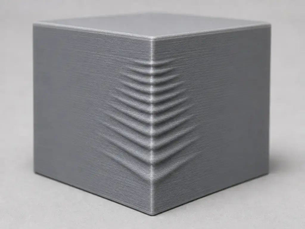
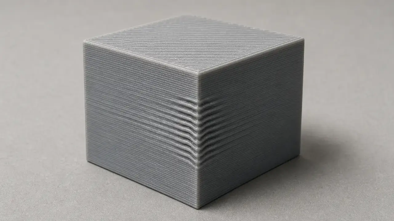
The easiest place to spot it is near sharp corners, embossed text, holes, logos, and other abrupt features that force a quick direction change. Simplify3D uses a 20 mm cube as a simple example because each face transition creates a sudden directional change, and Prusa describes the same pattern of decaying waves after an edge. [16] [12] The fade matters: the ripples usually get smaller as they move away from the feature, which suggests a vibration response rather than a fixed geometric error. [4]
The key diagnostic question is whether the marks are feature-linked and decaying or fixed in the same place layer after layer. VFAs are different: Prusa describes them as microscopic imperfections repeating at the same point in each layer, creating vertical lines that can become visible from 10 μm and are most noticeable around 40 μm peak-to-valley. [13] Seam or corner blobs are different again, because pressure-advance-style features target extrusion pressure behavior during corners rather than toolhead resonance. [7] If you identify the wrong defect family, you will apply the wrong fix.
| Artifact | Typical visual clue | Likely mechanism | First check |
|---|---|---|---|
| Ghosting / ringing | Repeated waves trailing away from a sharp feature. [12] [16] | Toolhead vibration or resonance after a quick direction change. [4] | Corners, face orientation, belts, pulleys, carriage play, and frame stiffness. [4] |
| Vertical Fine Artifacts (VFAs) | Fine vertical lines fixed to the same location from layer to layer. Visible from about 10 μm and worst around 40 μm peak-to-valley. [13] | Microscopic repeat errors in the motion system. [13] | Whether the line stays locked to one surface position across layers. [13] |
| Seam / corner blobs | Localized zits or bulges at starts, stops, or seam positions. [7] | Extrusion pressure and restart behavior, not resonance. [7] | Seam placement, restart behavior, and pressure tuning. [7] |
| Belt / drive periodic marks | Repeating marks at a regular interval rather than a decaying echo. | Drivetrain periodicity or transmission-related repeat error. | Belt condition, pulley grip, idlers, and drive path. [4] |
| Z wobble / banding | Horizontal bands wrapping around the part. | Z-axis motion or lead-screw related variation. | Z-axis straightness, coupling, and vertical motion hardware. |
| Infill showing through | Internal pattern visible on the skin. | Insufficient top-surface coverage or thin outer skin. | Top thickness, wall strategy, and surface coverage settings. |
Why Ghosting Happens: Vibration, Resonance, and Direction Changes
Ghosting is a dynamic response problem. When the toolhead changes direction suddenly near a corner, inertia keeps the moving mass trying to continue along its previous path. [16] At the same time, parts of the machine — belts, frame members, gantry parts, bed supports, mounts, and carriages — flex slightly and then rebound. [4] That stored energy does not disappear instantly, so the printer briefly oscillates after the move. The visible waves on the part are the record of that oscillation, and they usually decay because damping in the structure gradually dissipates the energy. [4]
That is why speed, acceleration, and corner handling are related but not interchangeable. Lowering speed can help, but if acceleration or cornering remains aggressive, the printer may still excite the same resonance. Simplify3D points readers to both print speed and firmware acceleration, while Marlin distinguishes classic jerk from Junction Deviation and notes that Junction Deviation is now the default mode. [16] [10] Klipper uses a different label again: square_corner_velocity is the maximum velocity through a 90° corner, with a default shown as 5 mm/s in the config reference. [6]
Ghosting Fix Workflow
Change one thing at a time and reprint the same test object after each adjustment. A 20 mm cube is enough to reveal ringing, and a controlled ringing tower is even better when you want axis-specific clues. [16] [4]
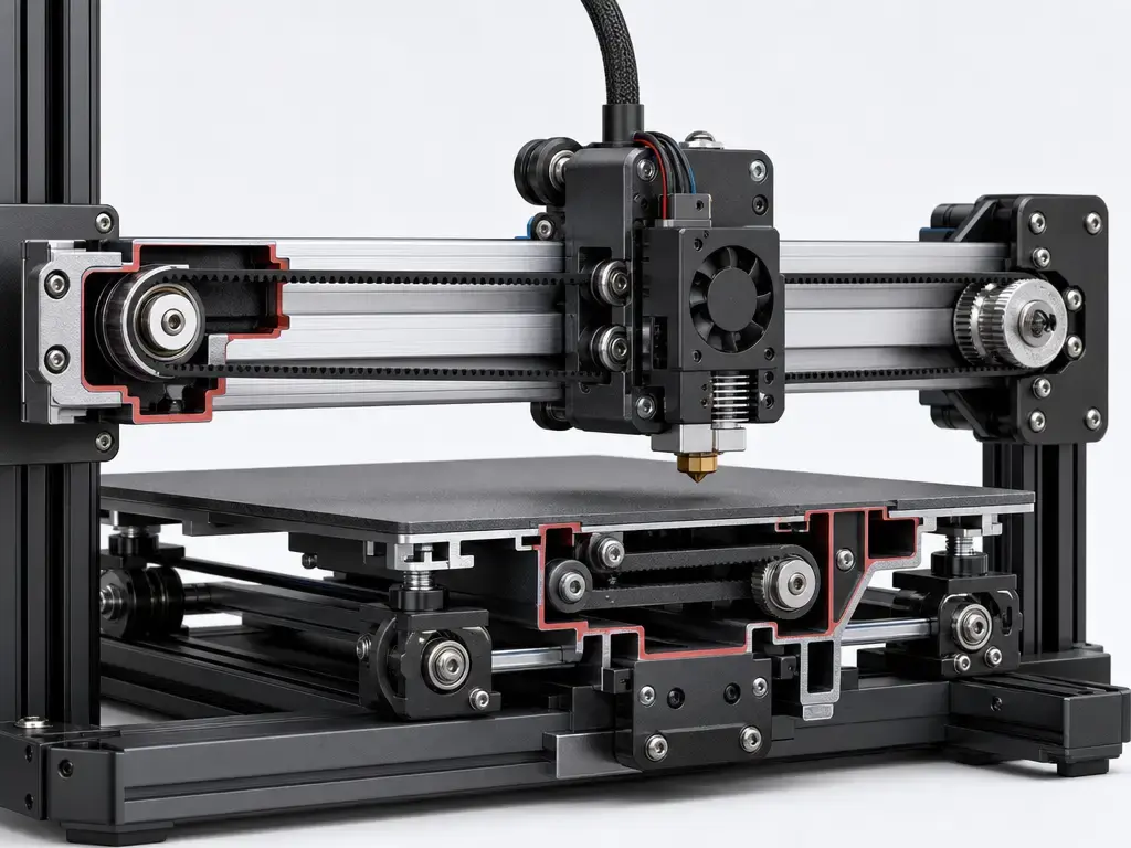
Mechanical inspection comes before firmware tuning. Klipper explicitly says ringing usually has mechanical origins, so start with belts, pulley set screws, idlers, rails, wheels or bearings, carriage looseness, frame fasteners, bed carriage play, spool drag, and the rigidity of the table or stand under the printer. [4] If you use vendor tools, treat them as ecosystem-specific examples, not universal belt standards. Prusa’s belt-status values of 240–300 apply to specific printer families, with lower numbers indicating more belt tension and higher numbers indicating a looser belt. [12]
After the mechanical pass, tune motion behavior in a controlled order. Reduce the acceleration affecting visible walls first if your slicer or firmware lets you separate it, then lower wall speed modestly if needed, and only then apply shaping or compensation. [16] [10] [6] Vendor workflows also show why re-testing matters: Bambu’s manuals pair belt maintenance with a fresh vibration-compensation calibration, and one P2S procedure uses 4 tension screws, 1–2 turns of loosening, 3–5 rotations of toolhead movement, and then re-tightening before calibration. [14] [15]
- Print a corner-rich test object such as a 20 mm cube or a ringing tower, and keep that model constant for all comparisons. [16] [4]
- Label which faces correspond to X and Y behavior so you do not mix up axis-specific symptoms. Klipper’s ringing tower uses X and Y marks for this exact reason. [4]
- Inspect belts, pulleys, toolhead carriage, bed carriage, frame joints, spool path, and the support surface for looseness or compliance before changing firmware settings. [4] [12]
- Reprint with lower wall-focused acceleration if that control is available, while keeping other major settings fixed. [16]
- If ringing remains, lower outer-wall speed modestly and re-test instead of changing several motion variables at once. [12] [16]
- If supported, calibrate input shaping or resonance compensation only after the basic mechanics are stable. [4] [9]
- Re-test after hardware, belt, mass, stiffness, or placement changes, because the resonance picture can shift when the machine changes. [4] [14] [15]
Motion Settings: Who Controls What?
Slicers usually request move speeds and sometimes accelerations, but firmware still owns motion planning, limit enforcement, and corner handling. That is why the same slicer profile can behave differently on two printers running different firmware. [16] [10] The practical goal is not to memorize labels, but to know whether you are changing requested speed, acceleration ramping, cornering behavior, or a compensation feature.
Do not port “jerk” advice blindly between firmware stacks. In Marlin, classic jerk and Junction Deviation are distinct, and M205 includes J<deviation> for Junction Deviation. [10] [11] In Klipper, square_corner_velocity is not a Marlin jerk clone; it is the maximum velocity through a 90° corner. [6]
| Concept | Usually changed in | Marlin / Klipper terms | What it affects |
|---|---|---|---|
| Print speed | Mostly slicer. [16] | Feedrate request / velocity request. | Requested move speed. Firmware may still cap it. |
| Acceleration | Slicer, firmware, or both. [16] [10] | Marlin M204 / Klipper acceleration settings. |
How quickly the printer ramps into and out of speed. |
| Cornering model in Marlin | Firmware. [10] [11] | Classic jerk or Junction Deviation, with Junction Deviation now the default mode. M205 includes J<deviation>. [10] [11] |
How aggressively the planner carries speed through corners. |
square_corner_velocity in Klipper |
Firmware. [6] | square_corner_velocity, default shown as 5 mm/s. [6] |
Maximum velocity through a 90° corner, not a generic slicer speed control. [6] |
| Input shaping | Firmware. [4] [8] [9] | Klipper input shaper / Marlin M593. |
Reduces resonance excitation after characterization; it is not a loose-hardware fix. |
| Pressure advance / Linear Advance | Firmware. [7] [9] | Klipper Pressure Advance / Marlin Linear Advance family. | Reduces ooze and corner blobbing; in Klipper it does not change toolhead path or timing. [7] |
Input Shaping / Resonance Compensation
Input shaping changes motion commands so the printer excites resonant modes less strongly. It is a compensation tool, not a substitute for loose belts, slipping pulleys, poor alignment, or a flexible frame. Klipper is especially clear on the order of operations: check mechanical causes first, and if the ringing pattern on the test print does not follow the curved-notch pattern, the defect is probably not true ringing. [4]
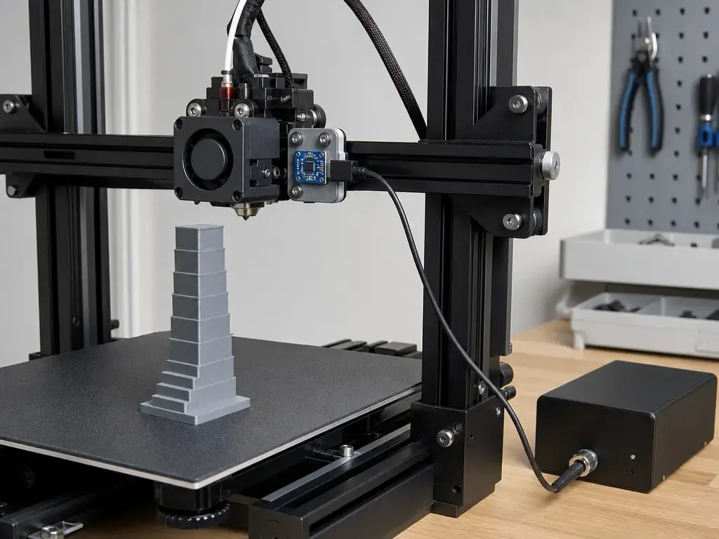
Klipper’s documentation provides a workflow example, not universal defaults. Its ringing-tower guidance uses a suggested layer height of 0.2 or 0.25 mm, external perimeter speed around 80–100 mm/s, minimum layer time at most 3 seconds, and an acceleration tower starting at 1500 mm/s² with 500 mm/s² steps every 5 mm up to 7000 mm/s². [4] The same page explains the printed-oscillation estimate as V · N / D, with the example 100 mm/s × 6 / 12.14 mm ≈ 49.4 Hz, and it uses X and Y marks so you measure each axis separately. [4] If you want instrumented tuning instead of visual tuning, Klipper supports ADXL345, MPU-9250, LIS2DW, and LIS3DH compatible accelerometers. [5]
Marlin documents a different boundary. Its input-shaping feature page says Marlin first introduced ZV Input Shaping in version 2.1.2 and notes that the largest oscillations are typically in a low-frequency band of about 10–50 Hz in Marlin’s context. [8] The M593 page says Marlin does not provide accelerometer-based tuning there, and recommends either a ringing tower or a frequency sweep. [9] It also says frequency-sweep patterns are printed with Linear Advance disabled, and that you may need to recalibrate the K-factor after tuning input shaping. [9] Input shaping is therefore separate from pressure advance or Linear Advance, which address extrusion pressure behavior instead of toolhead vibration. [7] [9]
If the measured resonance is very low — below about 20–25 Hz, and especially around 25 Hz and below — Klipper warns that shaping can create too much smoothing. In those cases, reducing moving mass or stiffening the machine may be a better first step than leaning harder on compensation. [4]
Printer Types and Axis-Specific Behavior
Resonance is axis-specific and configuration-specific. A printer can ring differently on X and Y, and the result can change after a direct-drive conversion, a heavier bed plate, a new fan duct, different belt tension, or a stiffer mount. Klipper also notes that ringing frequency can depend on model position and Z height, especially on delta printers. [4] Any change to mass, stiffness, or machine placement is a good reason to re-test. [4] [14] [15]
- Bedslinger: A moving bed adds mass to one axis, so the resonance picture can differ between axes and can shift as the print grows. [4]
- CoreXY: Belt path accuracy, pulley alignment, and frame rigidity strongly influence how much corner energy is stored and released.
- Direct-drive toolhead: Added carriage mass can lower resonance frequency, so upgrades should be followed by a new test. [4]
- Delta: Resonance can vary across the build volume, and Klipper notes that EI may fit better than MZV or ZV in some cases. If resonance is above about 50–60 Hz, testing
2HUMP_EIcan be considered with caveats. [4] - High-speed enclosed printers: Some vendor ecosystems include built-in vibration compensation, but the manuals still tie calibration back to belt maintenance. [14] [15]
Measuring Improvement
For most users, the most useful measurement is repeatability. Print the same model in the same orientation, under the same lighting, and compare how far the ripples extend and how quickly they decay. [4] That is more honest than trying to extract lab-grade roughness from a phone photo. If you want a rough frequency estimate, Klipper’s printed-tower method uses V · N / D, with the documentation example 100 mm/s × 6 / 12.14 mm ≈ 49.4 Hz. [4]
Lab work is different. ISO/ASTM 52902:2023 covers AM test artefacts and geometric capability assessment, but it does not define a universal ghosting score or prescribe one measurement method for this defect family. [2] ISO/ASTM 52900:2021 is vocabulary framing only, not a quality metric. [1] Research papers may use roughness or relative-motion metrics instead; one study reported roughness standard deviation increasing by more than 85%, from 187.71 μin to 349.01 μin, and a passive-control setup reducing relative motion by 93%, from 23.71 to 1.75 g/g, while improving surface roughness by 16%, from 1015.60 to 850.39 μin. [18] Those are study-specific results, not consumer thresholds.
Limits, Failure Modes, and Misdiagnosis Traps
Input shaping cannot fix loose hardware, a slipping pulley, poor frame rigidity, or an extrusion problem that only looks like vibration. Klipper explicitly says that if the ringing on the test print does not follow the curved-notch pattern, then the defect is not really ringing and has a different origin that should be fixed first. [4] Pressure advance is also not a substitute, because it addresses extrusion-pressure effects rather than changing the toolhead path or timing. [7]
There is also a low-frequency trade-off. Klipper warns that at about 25 Hz and below, even MZV may create too much smoothing, which can trade visible ghosting for rounded corners or softened detail. [4] If the printer is mechanically weak or the support surface is poor, firmware compensation may hide the symptom without removing the cause.
Research Context and Market Direction
Research supports the basic idea that vibration can measurably affect part quality, but the numbers are study-specific context, not consumer targets. One open-access study identified vibration-sensitive components near about 40 Hz and reported that base vibration had about a 600× larger measured effect on part quality than machine operation alone. [18] The same paper reported the roughness and relative-motion changes noted above. [18] A 2019 MDPI paper reported study-specific dimensional-error reductions of 28.57% on X, 78.26% on Y, and 62.5% on Z after structural optimization, with the reported cumulative error angle corrected from 70° to 90°. [19] Another MDPI study used a Folger Tech FT-5 R2 printer with a 300 × 300 × 400 mm build area and a 12 V, 6800 rpm vibration motor controlled with M106 SXXX, which underlines how system-specific these experiments are. [20]
On the product side, vendor manuals increasingly package vibration compensation as a built-in calibration feature. Bambu’s X2D manual defines vibration compensation as detecting and compensating for vibration during printing to reduce acceleration artifacts and increase print speed. [14] But those same manuals still connect compensation to belt maintenance and recalibration steps, which is the practical point: automation reduces tuning effort, not the need for sound mechanics. [14] [15]
Practical Guidance
The practical rule is simple: start with mechanics, then tune motion, then use shaping if the platform supports it. Resonance is printer-specific and axis-specific, so there are no universal best values here for mm/s, mm/s², belt tension, jerk, or resonance frequency. [4] Old settings should not be treated as permanent after changes in belts, carriage mass, frame stiffness, or printer placement. [4]
Treat vendor belt numbers the same way. Prusa’s 240–300 belt-status range is valid in that printer ecosystem, which is why it should not be copied blindly to every other machine. [12] For 3D printing ghosting, the best fix is the one that matches the actual motion system in front of you.
FAQ
What is 3D printing ghosting?
It is the visible echo pattern of several waves that follow a sharp edge or raised feature on a print. In FFF/FDM troubleshooting, it is usually discussed alongside ringing because both terms refer to the same family of motion-related surface defects, with ghosting emphasizing the appearance and ringing emphasizing the mechanism. [12] [4]
What causes ringing in 3D prints?
Ringing comes from inertia, sudden direction changes, and machine compliance. When the toolhead changes direction at a corner, the moving parts do not stop instantly, so the machine flexes and briefly oscillates. Those oscillations then fade as the structure damps them out, which is why the marks usually decay away from the edge instead of staying constant. [16] [4]
Ghosting vs ringing vs VFAs — how do I tell?
Ghosting and ringing are the decaying waves that trail a feature after a direction change. VFAs are different because they repeat at the same point in each layer, forming fixed vertical lines. Prusa describes VFAs as visible from about 10 μm and worst around 40 μm peak-to-valley, which makes them a coordinate-fixed artifact rather than a corner-triggered echo. [13] [4]
Should I reduce speed or acceleration first?
Usually acceleration is the more direct motion setting to examine first, because it controls how abruptly the printer loads the structure during direction changes. Lowering speed can also help, but it is not a guaranteed cure if corner handling and acceleration remain aggressive. The safest method is to make one controlled change, reprint the same test object, and compare the result. [16] [10]
Expert — How do I estimate ringing frequency from a printed tower?
Klipper documents a simple estimate using V · N / D, where V is outer-perimeter velocity, N is the number of oscillations, and D is the measured distance they span. The example in the docs is 100 mm/s × 6 / 12.14 mm ≈ 49.4 Hz. Measure X and Y separately, because each axis can have a different resonance. [4]
Expert — Why can input shaping round details or over-smooth prints?
Because shapers trade some sharpness for vibration reduction. Klipper warns that at very low ringing frequencies — roughly 20–25 Hz, and especially around 25 Hz and below — even MZV may create too much smoothing. In that situation, stiffening the printer or reducing moving mass may protect detail better than leaning harder on compensation. [4]
Do I need to re-tune pressure advance or Linear Advance after input shaping?
Often, yes. Marlin’s M593 guidance says frequency-sweep patterns are printed with Linear Advance disabled, and that the K-factor may need recalibration after tuning input shaping. [9] That makes sense because pressure-control features and input shaping solve different problems: pressure advance reduces corner blobbing, while in Klipper it does not change the toolhead path or timing. [7]
Related on 3D Mag
- Pillowing in 3D Printing: Causes and Fixes
- Elephant Foot 3D Printing: Causes and Fixes
- Under Extrusion 3D Printing: Causes and Fixes
Sources
- ISO — ISO/ASTM 52900:2021 (Fundamentals and vocabulary)
- ISO — ISO/ASTM 52902:2023 (Test artefacts / geometric capability assessment)
- NIST — Additive Manufacturing Technologies (Material Extrusion section)
- Klipper — Resonance Compensation
- Klipper — Measuring Resonances
- Klipper — Config Reference (
square_corner_velocity) - Klipper — Pressure Advance
- Marlin — Input Shaping feature page
- Marlin — M593 (ZV Input Shaping)
- Marlin — Configuration (jerk + junction deviation context)
- Marlin — M205 (advanced settings incl.
Jjunction deviation) - Prusa — Ghosting (KB)
- Prusa — VFA article (PrusaSlicer surface finish / VFA)
- Bambu Lab — X2D User Manual (PDF)
- Bambu Lab — P2S User Manual (PDF)
- Simplify3D — Vibrations and Ringing
- RepRap Wiki — Print Troubleshooting Pictorial Guide
- Jensen, Parker, Blough — Base Vibration Effects on Additive Manufactured Part Quality (Experimental Techniques, OA)
- Zhao et al. — Optimization of Vibration Characteristics… (Applied Sciences, MDPI, 2019)
- Rafiq et al. — FDM with Induced Vibrations… (Applied Sciences, MDPI, 2022)