Summary
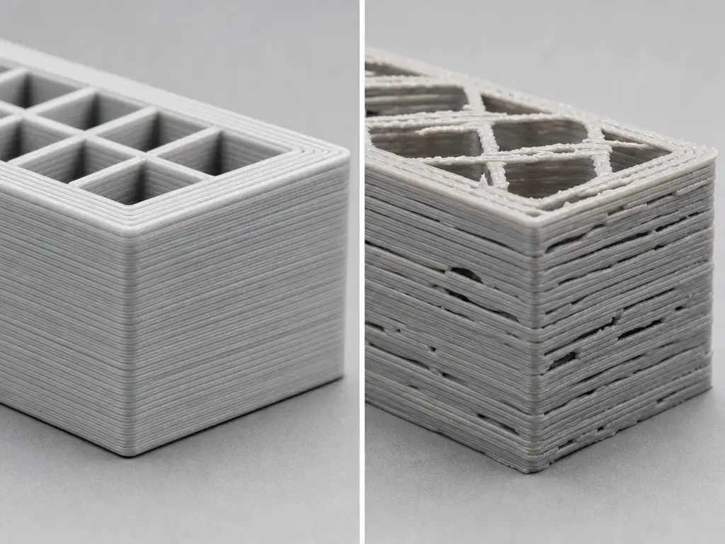
Under extrusion 3d printing means the machine deposits less material than the toolpath expects, which shows up as missing material, gaps, incomplete lines, and parts that feel weak or fragile. [S06]
The safest under-extrusion fix order is diagnostic, not reactive: confirm the symptom, rule out slicer-generated wall gaps, check for first-layer obstruction, then inspect nozzle restriction, filament feed, and throughput limits. Only after that should you tune flow or calibration. Because the printer does not directly measure how much filament actually leaves the nozzle, a commanded extrusion value is not proof that the intended amount was deposited. [S06] [S10]
What under-extrusion means and what it does not mean
Under-extrusion is an observed outcome, not a single fault. It describes too little plastic reaching the printed path, whether the root cause is a partial clog, wrong slicer inputs, feed slip, heat creep, or a first-layer clearance problem. That distinction matters because similar-looking gaps can come from very different failure modes, and they are not fixed the same way. [S06] [S20]
This article is about material extrusion, the ISO/ASTM-defined additive manufacturing process in which material is selectively dispensed through a nozzle or orifice. [S01] [S02] In standards and industry use, this family is also called MEX, FLM, FDM, or FFF, but FDM is also a Stratasys trademark, so FFF or material extrusion is the safer generic wording. NIST notes that material extrusion builds 3D structures layer by layer and is common in both personal and commercial printers. [S03] [S04] [S05]
What under-extrusion looks like
The first signs are usually visual: thin or broken wall lines, weak top surfaces, missing layers, thin infill, poor layer adhesion, or a part that feels brittle instead of solid. [S06] A partial clog can look similar, and Prusa’s clogged-nozzle guide adds two useful clues: filament that curls as it exits the nozzle, and filament that sticks to the nozzle instead of flowing cleanly. Clicking can help, but it is still only a clue: loud clicking often points to a clogged or deformed nozzle, while lighter clicking can point to gearing. [S20]
Do not diagnose from one symptom alone. Some gaps are produced by constant line-width path planning, and a nozzle that is too close to the bed can obstruct first-layer flow enough to mimic under-extrusion. [S10] [S06] This is why a typical “gaps in walls 3d print” complaint does not always indicate a true extrusion fault. [S10]
Common signs of under-extrusion include the following. [S06] [S20]
- Gaps between wall lines
- Gaps in top surfaces
- Missing layers or lines
- Thin infill
- Poor layer adhesion or weak parts
- Brittle walls
- Clicking or grinding
- Inconsistent line width
Key terms before you change any settings
Before changing settings, separate geometry terms from calibration terms. Nozzle diameter is the physical opening in the hardware, while line width or extrusion width is the bead width the slicer plans to lay down. [S19] Layer height is the vertical thickness of each layer, and volumetric flow is the amount of material demanded per second in mm³/s. Prusa frames maximum volumetric speed with the relationship Layer Height × Extrusion Width × Speed, which is why a print can look fine at one setting and then start starving when speed, line width, or layer height pushes the hotend past its melt capacity. [S14]
Flow or extrusion multiplier is a slicer-side scalar that changes how much material the slicer requests. [S18] E-steps, by contrast, are firmware steps-per-unit, including the extruder value set through Marlin’s M92 command in Marlin-style systems. [S17] Marlin’s volumetric mode changes the math again by treating E as mm³ and calculating extrusion length from filament diameter. These settings interact, but they are not interchangeable fixes. [S16] [S17] [S18]
| Term | Where it lives | What it changes | What it cannot fix |
|---|---|---|---|
| Nozzle diameter | Hardware | Physical outlet size and slicer machine-limit assumptions | A partial clog or feed slip |
| Extrusion width / line width | Slicer | Planned bead width and wall planning | A blocked nozzle or slipping feeder |
| Volumetric flow limit (mm³/s) | Slicer / profile | Maximum material demand sent to the hotend | Gear debris or heat creep |
| Extrusion multiplier / flow % | Slicer | Requested material per path | A nozzle restriction or bad first-layer Z offset |
| E-steps / steps-per-mm | Firmware | Extruder motion per command | A clog, heat creep, or slicer geometry gap |
If Default extrusion width is set to 0 in PrusaSlicer, the program derives width from nozzle diameter using 1.125× nozzle diameter. [S19]
Fast triage: symptom-to-cause matrix
Patterns are more useful than isolated clues. The same visible gap can come from first-layer obstruction, slicer planning, a restriction, or a melt-rate limit, so the first job is to decide which branch you are actually in. [S06] [S20] [S22]
| Symptom pattern | Likely cause (failure mode) | First check | Fix type |
|---|---|---|---|
| First layer only | Nozzle too close / Z-offset back-pressure [S06] | First-layer pattern and nozzle-to-bed gap [S06] | Recalibration |
| Gaps + curling filament | Partial clog / restriction [S20] | Controlled extrusion and nozzle inspection [S20] | Clean or replace |
| Clicking or grinding | Overload indicator: restriction, slip, friction, gear debris, or insufficient melt capacity [S20] [S07] | Gear debris, filament path, nozzle resistance [S20] | Mechanical / thermal / process |
| Uniformly thin walls everywhere | Flow scalar or wrong filament inputs [S15] [S16] [S19] | Wall test, filament diameter, nozzle size, line-width settings [S15] [S16] | Calibration / profile |
| Fails only at high speed | Volumetric demand exceeds melt capacity [S14] [S07] | Speed, layer height, line width, MVS [S14] | Process setting |
| Random gaps late in print | Heat creep or rising drag [S22] [S24] | Cooling, enclosure, path friction, time into print [S22] | Thermal / mechanical |
Diagnostic workflow: confirm under-extrusion before fixing it
Before changing anything, preserve evidence. Save the slicer preview, photograph the failed area, note the filament, nozzle size, and profile used, and record how far into the print the defect appeared. A first-layer-only issue, a mid-print failure, and a speed-triggered failure are different problems even when they all look like missing material.
Change one variable per test. If you raise flow, lower speed, and clean the nozzle at the same time, you may get a better result without learning what actually fixed it. Small repeatable tests are more useful than guesswork.
- Compare the slicer preview with the failed print and look for thin-wall or gap-fill artifacts. [S10] [S13]
- Inspect the first layer and Z offset for obstruction signs. [S06]
- Extrude or load filament and watch for curl, skipping, or uneven flow. [S20]
- Check for restriction or partial clog in the nozzle or hotend path. [S20]
- Check drive-gear debris and idler or tension behavior using device-specific guidance. [S20] [S21]
- Verify slicer inputs: nozzle diameter, line width, filament diameter, and volumetric-mode assumptions. [S19] [S16]
- Reduce volumetric demand with speed, width, or layer-height changes, or use a volumetric limit if your workflow provides one. [S14]
- Tune extrusion multiplier or flow only after mechanical checks. [S18]
- Reprint a small controlled test and document the delta.
Why slicer and model artifacts can look like under-extrusion
A wall gap is not automatically a flow failure. UltiMaker’s Cura documentation shows that with constant line width, a feature that is effectively two-and-a-half lines wide may be planned as two lines with a small gap between them. [S10] UltiMaker’s Arachne example makes that more concrete: a 4.4 mm feature sliced as four constant 1.0 mm lines can leave a 0.4 mm gap, while variable width can instead use 1.1 mm lines to fill it. [S11]
Prusa documents the same distinction from the other side. Arachne uses variable extrusion widths, and Detect Thin Walls is disabled when Arachne is active because Arachne already adapts to thin features. [S12] Prusa also notes that Detect Thin Walls can generate a single perimeter, but walls thinner than a single perimeter extrusion width may still be ignored. If the preview already contains the gap, treat it as a geometry or line-planning limitation, not under-extrusion. [S13] [S10]
Root causes and fixes in the right order
Under-extrusion symptoms can stack. One print can have a slicer artifact in one region, a mild first-layer obstruction, and a high-flow failure later in the job. The safest workflow is to start with preview-visible causes, then first-layer clearance, then restriction and feed, then throughput, and finally calibration.
Slicer or model causes, not true under-extrusion
If the slicer preview already shows the missing line, the printer is probably doing what it was asked to do. Constant line-width engines can leave small voids in thin features, while variable-width engines such as Arachne can often fill the same geometry more effectively. [S10] [S11] [S12] The fix is usually geometric or slicer-related: change wall thickness, change line-width strategy, or change perimeter-generation behavior. [S10] [S13]
Do not use flow to hide a preview-visible gap. Flow changes do not change the planner’s geometry decision, and they can distort dimensions in the parts of the model that were already printing correctly. [S10] [S18]
First-layer back-pressure
A first-layer-only defect is its own branch. Prusa explicitly warns that if the nozzle is too close to the bed, filament can be obstructed from pushing through. [S06] That can produce a starved-looking first layer even when the hotend and feeder are otherwise healthy. If later layers look normal, treat the problem as first-layer clearance first, not as general extrusion calibration. [S06]
Restriction or partial clog: nozzle and hotend path
A partial clog is one of the most common real causes because it often looks like calibration trouble at first. Prusa’s clogged-nozzle guide lists gaps, missing layers, curling filament, and filament sticking to the nozzle as key indicators. Clicking can appear here too, but the sound only tells you the extruder is meeting resistance somewhere in the path. [S20]
Start with controlled extrusion. If the flow is inconsistent, curls upward, or the extruder skips, inspect the nozzle and melt path before touching flow settings. Flow tuning cannot fix a narrowed melt path. [S20]
Example (Prusa-specific). Prusa’s cleaning examples include a 0.3 to 0.35 mm wire inserted about 1 to 2 cm, and a separate “push new filament” procedure using about 40 cm of PLA with the nozzle set to 260 °C after PLA or 280 °C after PETG or ASA, followed by a 2 minute wait. Those numbers are example-only for that guide, not universal settings, and hot metal and molten plastic are burn hazards. [S20]
Mechanical feed issues: gear debris, idler tension, and drag
The extruder can lose traction before the hotend is the main problem. Prusa notes that debris can collect in the feeding-gear grooves and cause insufficient extrusion. That usually shows up as intermittent gaps, inconsistent deposition, or clicking that persists even when the nozzle is not fully blocked. [S20]
Idler tension is also design-specific. Prusa’s own guidance uses different visual or millimeter references across models, which is exactly why you should not copy one printer’s screw position to another. Use your machine family’s reference if it has one; otherwise, treat idler adjustment as a machine-specific mechanical check, not a universal number. [S21]
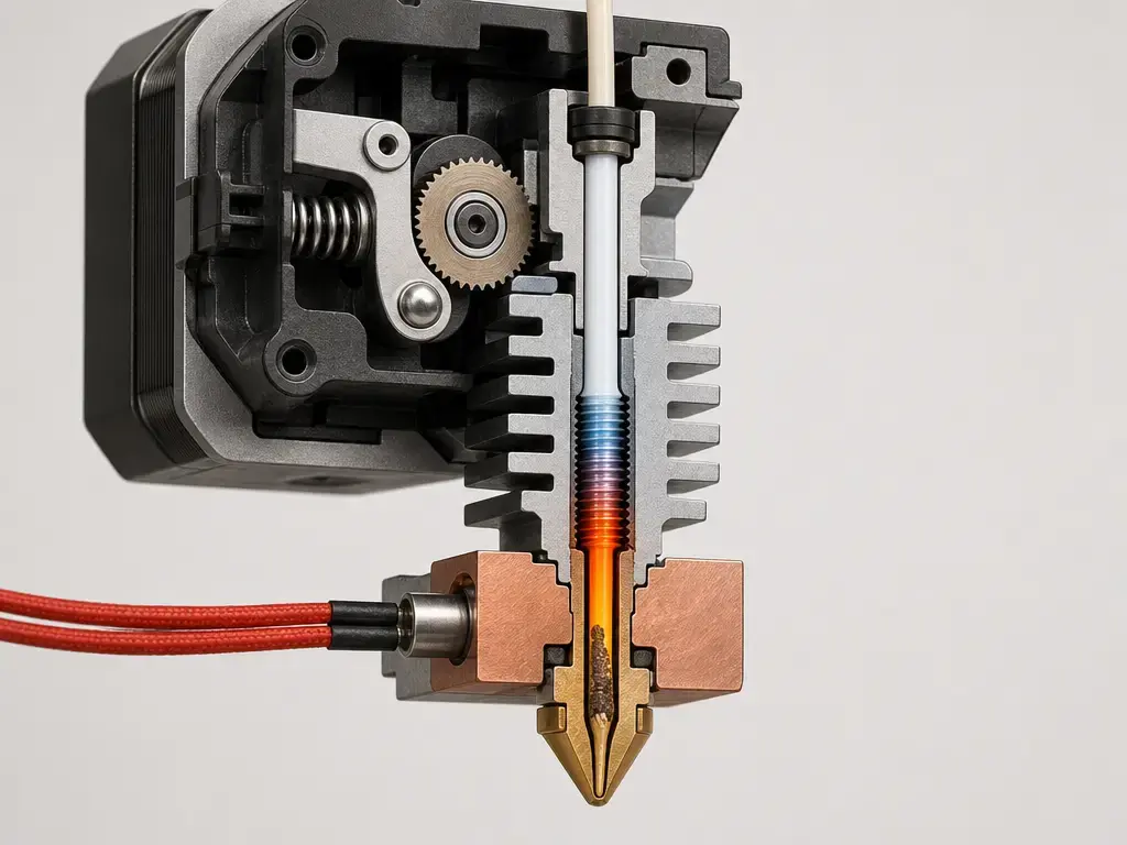
Thermal limits and throughput
High-speed failures are often melt-rate failures, not feeder failures. NIST’s steady-melting work links hotend temperature and temperature variance to volumetric flow rate, setpoint, and nozzle diameter, and it notes that non-isothermal hotends are tied to print defects. [S07] In practice, that means the same printer can succeed at one demand level and start starving at another even when the nozzle is clean. [S07]
The first fix is to reduce demand. Prusa’s MVS framing uses Layer Height × Extrusion Width × Speed, so lowering any of those lowers the hotend’s required throughput. [S14] UltiMaker’s older schooling example makes the same idea concrete with a stock-machine example of about 8 mm³/s and a sample calculation of 100 mm/s × 0.4 × 0.2 = 8 mm³/s. That number is device-specific, but the diagnostic rule is general. [S15]
Heat creep
Heat creep is the time-dependent branch. Prusa describes it as heat moving too far up the hotend so the filament softens too early and causes a clog, while E3D describes the same mechanism as heat traveling up the hotend or cold side so the filament liquifies early and expands above the intended transition zone. [S22] [S23] [S24]
That is why a print can start well and fail later. Prusa lists contributors such as ambient temperature above 35 °C, or 30 °C for some filaments, enclosure use, excessive hotend temperature, insufficient airflow, and slow extrusion that lets the filament absorb more heat. If the defect appears later rather than immediately, look at cooling and heat buildup before chasing slicer flow numbers. [S22]
Wrong inputs: filament diameter and volumetric-mode mismatch
Sometimes the printer is obeying bad math. UltiMaker’s documentation notes that material flow depends on values such as filament diameter and recommends checking that value when changing filament. [S15] Marlin’s volumetric mode makes the dependency explicit: in volumetric extrusion mode, E is interpreted as mm³, and firmware calculates the required filament length from the configured diameter. If filament diameter or volumetric-mode assumptions are wrong, the result can look like under-extrusion even though the mechanics are fine. [S16] [S15]
Calibration choices: flow, throughput, and E-steps
Flow or extrusion multiplier is the right lever when the printer is mechanically sound but the print is still consistently a little light or heavy. In Prusa’s wall-thickness method, the documented baseline assumptions are a 0.4 mm nozzle, 0.45 mm extrusion width, and 0.1 to 0.2 mm layer height, with extrusion multiplier calculated as 0.45 divided by the average measured wall thickness from three or more measurements. [S18] Prusa also documents 1 to 2% visual adjustments for minor top-surface under-extrusion in that preset context. [S18]
E-steps are different. In Marlin-style ecosystems, M92 sets axis steps-per-unit, including the extruder value, so E-steps belong to firmware motion calibration. [S17] On Prusa’s under-extrusion page, a support reply says that when the issue is not hardware- or filament-related, they generally prefer extrusion multiplier calibration rather than modifying E-steps. [S06] Bambu’s manual reaches a similar decision point from a different ecosystem: flow-rate issues are real, but under-extrusion is not always caused by flow rate, and users should check basic calibration items and model structure first. [S25]
Change this, not that:
- If your platform exposes M92 or steps-per-mm and expects calibration, E-steps can matter after mechanical checks. [S17]
- If your ecosystem emphasizes slicer-side flow calibration workflows, prefer that for filament or profile tuning. [S25]
- For Prusa-style guidance, prefer extrusion multiplier calibration rather than E-steps unless the manufacturer explicitly says otherwise. [S06]
- If the defect tracks speed or material demand, reduce throughput before touching calibration. [S14]
- Never use flow to paper over a partial clog or heat creep. [S20] [S22]
Special cases
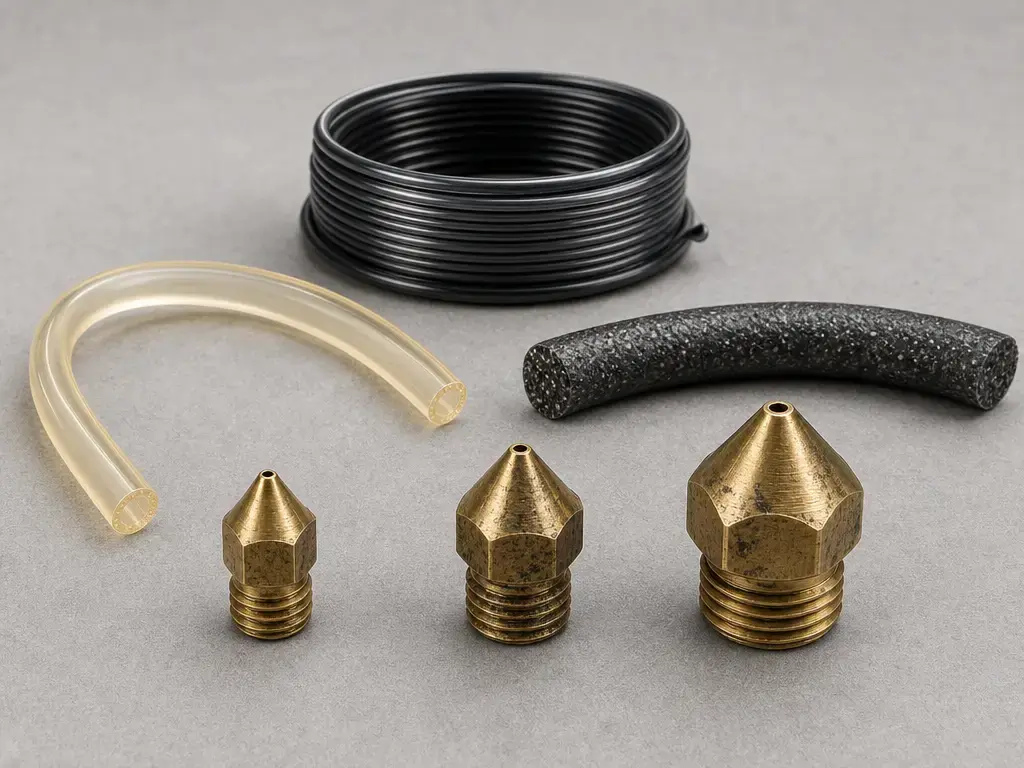
Flexible filaments deserve their own branch because the filament path becomes part of the problem. Bambu states that TPU easily absorbs moisture and has higher requirements for storage, dryness, and loading method. If TPU under-extrudes, do not assume the problem is only flow rate; check for buckling, drag, and inconsistent delivery to the hotend. [S25]
Filled, composite, and abrasive filaments raise clog risk. A particle-filled-polymer study reported an ordinary FFF printer maximum extrusion force around 62 N and found complete clogging when D/d ≤ 6.2, with intermittent clogging causing under-extrusion. [S09] Prusa’s nozzle table is brand-specific, but it also shows why nozzle size choice matters: it references 0.25 mm, 0.4 mm, and 0.6/0.8 mm use cases and notes Prusament diameter tolerance of ±0.02 mm. [S27]
Wet filament is a confounder, not a universal explanation. Forward AM’s moisture study reports that moisture can create bubbles and voids, decrease viscosity, and make the same G-code behave as under-extrusion when spool condition changes. If one spool fails and another prints well on the same machine, check material condition before re-tuning the printer. [S26]
Prevention: how to keep it from returning
Most prevention comes down to keeping the extrusion path predictable. Clean the feed path and drive gears so debris does not build up in the grooves and reduce grip. [S20] Keep profiles tied to the correct nozzle and filament so nozzle diameter, line width, and filament diameter assumptions do not drift from reality. [S19] [S16]
The other guardrail is throughput. Maximum volumetric speed is the useful concept here: a clean printer can still under-extrude if the hotend is asked to melt more material per second than it can handle. [S14] Keep cooling functional, watch enclosure conditions that can trigger heat creep, and store moisture-sensitive filament appropriately. [S22] [S25] [S26]
Current research context
The research value here is practical. NIST’s steady-melting work shows that hotend melt behavior changes with volumetric flow rate, setpoint, and nozzle diameter, which supports a simple troubleshooting action: if failures appear only when you push speed or bead size, reduce demand first and see whether the defect disappears. [S07]
Filled-material research explains why some filaments behave differently from plain rigid polymers. The particle-filled-polymer study’s D/d clogging threshold and intermittent-clogging result support a conservative rule: be more careful with filler-loaded materials and small nozzles, and treat unexplained starving as a material-choice issue as well as a machine issue. [S09] The broader FFF review’s four-part breakdown of the extrusion system also helps localize faults to the motor, barrel, heating block, or nozzle. [S08]
Key takeaways
Under extrusion 3d printing is the visible result of too little material being deposited for the intended path, but the cause may be slicer planning, first-layer obstruction, nozzle restriction, feed problems, wrong inputs, heat creep, or throughput demand. [S06] [S10] The safest fix is to follow the failure mode instead of jumping straight to flow.
Fix in this order:
- Slicer preview / thin walls
- First layer
- Restriction / clog
- Feeder path
- Throughput / volumetric demand
- Flow / extrusion multiplier
- E-steps only if applicable
FAQ
1) What causes under extrusion in 3D printing?
Usually it comes from one of several distinct failure modes: slicer over-demand, wrong filament or profile inputs, feeder slip or debris, partial clogs, heat creep, or first-layer obstruction. The useful question is not “what number do I change,” but “where in the extrusion path is material getting lost?” [S06] [S20] [S22]
2) What are the main 3D printing signs of under extrusion?
The common signs are gaps, missing layers, thin walls, thin infill, rough top surfaces, weak layer adhesion, and brittle parts. Clicking or grinding can help, but they are overload clues rather than proof of one specific fault. Also compare the print to the preview, because thin-wall planning can create similar-looking gaps without a real flow problem. [S06] [S20] [S10]
3) Is an under-extrusion fix always just increasing flow rate?
No. Flow can help a consistent, minor material shortfall, but it can also hide a clog, heat creep, or a geometry issue. Bambu’s manual explicitly says under-extrusion and over-extrusion are not always caused by incorrect flow rate and recommends checking basic calibration items and model structure first. [S20] [S22] [S25]
4) Why do I see gaps in walls in a 3D print even when my extruder seems fine?
Because the slicer may have planned them. With constant line width, thin features can leave small voids, while variable-width engines such as Arachne can often fill the same region more completely. If the preview already shows the gap, the problem is usually a geometry or line-planning limitation, not true under-extrusion. [S10] [S11] [S12] [S13]
5) Can printing too fast cause under-extrusion?
Yes. If volumetric demand exceeds what the hotend can melt and push, the print can starve even when the feeder is still trying to deliver material. Prusa’s MVS framing uses Layer Height × Extrusion Width × Speed, so reducing any of those lowers the load on the hotend. [S07] [S14]
6) How do I tell under-extrusion from poor bed leveling or Z-offset issues?
Look at where it happens. If the problem is mainly confined to the first layer, a nozzle that is too close to the bed is a strong possibility because it can physically obstruct flow. If the defect continues well beyond the first layer, move on to restriction, feed, wrong inputs, heat creep, or throughput. [S06] [S20]
7) Should I calibrate E-steps or extrusion multiplier for under-extrusion?
It depends on the platform and the evidence. In Marlin-style systems, E-steps are firmware steps-per-unit set through M92, while extrusion multiplier is a slicer-side flow scalar. Prusa-style guidance generally leans toward extrusion multiplier rather than E-steps for non-hardware cases, while Bambu’s manual says basic checks should come first. [S17] [S18] [S06] [S25]
Sources
All web sources accessed 2026-07-05.
- S01 — ISO official listing: ISO/ASTM 52900:2021, Additive manufacturing — General principles — Fundamentals and vocabulary — https://www.iso.org/standard/74514.html
- S02 — iTeh standards catalog excerpt: ISO/ASTM 52900:2021, material extrusion definition — https://standards.iteh.ai/catalog/standards/iso/482823e1-57b2-481f-87e7-11da730ba16f/iso-astm-52900-2021
- S03 — ASTM work item WK73239, MEX also known as FLM/FDM/FFF — https://www.astm.org/membership-participation/technical-committees/workitems/workitem-wk73239
- S04 — Stratasys legal information — https://www.stratasys.com/en/legal/legal-information/
- S05 — NIST, Material Extrusion — https://www.nist.gov/additive-manufacturing/research-areas/technologies/material-extrusion
- S06 — Prusa Knowledge Base, Under-extrusion — https://help.prusa3d.com/article/under-extrusion_2007
- S07 — NIST, Steady Melting in Material Extrusion Additive Manufacturing — https://www.nist.gov/publications/steady-melting-material-extrusion-additive-manufacturing
- S08 — Springer, Gaining a better understanding of the extrusion process in fused filament fabrication 3D printing: a review — https://link.springer.com/article/10.1007/s00170-021-06918-6
- S09 — OSTI, Nozzle Clogging Factors During Fused Filament Fabrication of Spherical Particle Filled Polymers — https://www.osti.gov/servlets/purl/1471198
- S10 — UltiMaker, Cura 5.0 variable line width explainer — https://ultimaker.com/learn/a-leap-forward-in-3d-printing-with-ultimaker-cura-5-0/
- S11 — UltiMaker, Arachne beta explainer — https://ultimaker.com/learn/get-an-engine-boost-with-ultimaker-cura-and-arachne-beta/
- S12 — Prusa Knowledge Base, Arachne perimeter generator — https://help.prusa3d.com/article/arachne-perimeter-generator_352769?product=cw1
- S13 — Prusa Knowledge Base, Layers & perimeters — https://help.prusa3d.com/article/layers-and-perimeters_1748?product=cw1
- S14 — Prusa Knowledge Base, Max volumetric speed — https://help.prusa3d.com/article/max-volumetric-speed_127176?product=mk3
- S15 — UltiMaker Schooling, material flow and speed — https://ultimaker.com/learn/ultimaker-schooling-3d-printing/
- S16 — Marlin Firmware, M200 Volumetric Extrusion Diameter — https://marlinfw.org/docs/gcode/M200.html
- S17 — Marlin Firmware, G-code index with M92 reference — https://marlinfw.org/meta/gcode/
- S18 — Prusa Knowledge Base, Extrusion multiplier calibration — https://help.prusa3d.com/article/extrusion-multiplier-calibration_2257
- S19 — Prusa Knowledge Base, Creating profiles for different nozzles — https://help.prusa3d.com/article/creating-profiles-for-different-nozzles_127540?product=mmu1
- S20 — Prusa Knowledge Base, Clogged nozzle (CORE One, CORE One L, XL, MK4/S, MK3.9/S) — https://cdn.help.prusa3d.com/article/clogged-nozzle-core-one-core-one-l-xl-mk4-s-mk3-9-s_411823
- S21 — Prusa Knowledge Base, Idler screw tension — https://help.prusa3d.com/article/idler-screw-tension_177367?product=xl
- S22 — Prusa Knowledge Base, Extrusion stopped mid-print (Heat creep) — https://cdn.help.prusa3d.com/article/extrusion-stopped-mid-print-heat-creep_1948
- S23 — E3D, Anatomy of a 3D Printer HotEnd — https://e3d-online.com/blogs/news/anatomy-of-a-hotend
- S24 — E3D, Revo cold sides: Everything you need to know — https://e3d-online.com/blogs/news/revo-cold-sides
- S25 — Bambu Lab P2S user manual PDF — https://csm.bblcdn.com/hub/9425242c00344b0e801b6179f9a243aa.pdf
- S26 — Forward AM moisture study PDF — https://move.forward-am.com/hubfs/AES%20Documentation/Reinforced%20Filaments/PET%20CF15/Sales%20Resources/moisture_study_PET_CF15.pdf
- S27 — Prusa Knowledge Base, E3D V6 nozzles — https://help.prusa3d.com/es/article/e3d-v6-nozzles_920168