
Summary
Pillowing in 3d printing is a top-surface closure defect on material extrusion parts, where the upper skin sags, gaps, or turns quilted because the final solid layers do not close cleanly over the support beneath them. In standards-oriented language, the process family is material extrusion, even though many users still say FDM or FFF, and the first checks are top shell thickness in millimeters, infill support, cooling, and under-extrusion as a possible look-alike. [1] [2] [3] [4]
What Is Pillowing in 3D Printing?
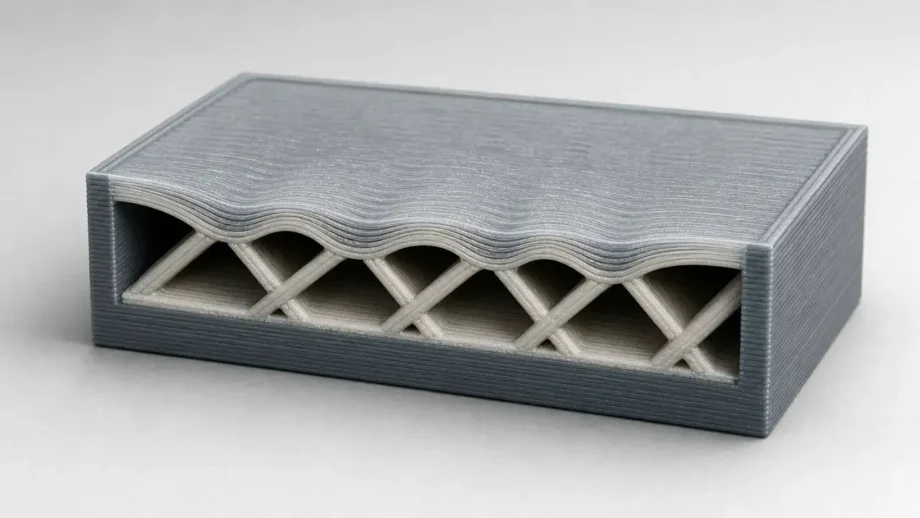
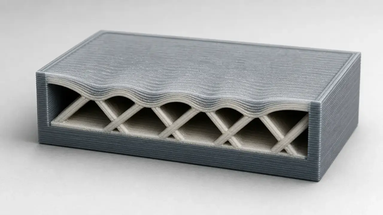
Pillowing is a common user term for a top-surface defect on material extrusion prints, where the roof of the part looks bumpy, gappy, slightly collapsed, or thin enough to reveal the infill underneath. It usually appears on upper horizontal faces after the rest of the print looks acceptable, so many users first notice it as top layer gaps rather than as a distinct defect category. Troubleshooting guides place it in the broader group of top-surface closure failures over a partially hollow interior. [2] [4]
The visible defect shows up where the top skin is being printed over internal support rather than over a fully solid base. Because infill helps support those upper solid layers, a poor-looking roof can result from sparse support, too little top thickness, or a broader extrusion problem that only becomes obvious on the final surface. [3] [4] [5]
Do not mix up:
- Pillowing.
- Sparse top fill or top layer gaps.
- Wall-edge pinholes.
- Global under-extrusion.
Terminology and Defect Boundaries
ISO/ASTM 52900:2021 is the vocabulary anchor for additive manufacturing, and NIST’s polymer AM guidance uses material extrusion as the formal term for nozzle-based deposition of thermoplastic material. In everyday shop use, many people still say FDM or FFF, but those labels are not the same as the standards family name. Here, pillowing is the visible defect, while material extrusion is the process class that produces the part. [1] [2]
The relevant slicer controls are also easy to blur together. OrcaSlicer separates shell layers, shell thickness, surface density, and infill/wall overlap, and notes that a 0 shell thickness setting disables that thickness constraint while 100% surface density produces a solid surface. That matters because a preview can look filled for one reason while the roof still fails for another. [4] [6]
Terms to keep separate:
- Material extrusion.
- FDM / FFF.
- Top solid layers / top shell layers.
- Infill density / infill pattern.
- Pillowing / wall gaps / under-extrusion.
Why Top Layers Sag Over Infill
Prusa describes top solid infill as essentially bridging over the infill pattern, which is the key to pillowing. The first roof layers are not landing on a fully solid slab. They are spanning small gaps between internal support lines. If the infill below is sparse, those spans get longer, the first solid lines sag more, and the final top face can stay visibly uneven or incomplete. Simplify3D describes the same failure mode from the troubleshooting side: the top surface has to cross hollow air pockets, so droop and gaps become more likely when the support below is weak. [3] [4] [5]
This is why top shell thickness in millimeters is the master metric, with layer count serving only as a conversion. Simplify3D gives a practical rule of thumb of at least 0.5 mm of solid top section, which translates to at least 2 top solid layers at 0.25 mm or 5 at 0.1 mm. Prusa shows the same scaling logic from another angle, suggesting at least 3 top layers and noting that 3 top layers at 0.3 mm can represent a similar physical thickness to 9 top layers at 0.1 mm. [3] [4]
Support density, geometry, heat, and cooling all interact. Simplify3D frames 10% infill as 90% hollow and suggests testing 50% if 30% still leaves gaps, while Prusa explains that infill exists partly to support top layers that would otherwise bridge empty space. Creality also notes that very high infill is not automatically better, because 80% or 100% infill can create shrinkage-related surface indentations in some cases. Prusa’s cooling and bridging guidance adds that bridges and overhangs need fast cooling, but it does not give one universal fan speed, bridge flow, or bridge speed value for every material and geometry. A 2025 pellet additive manufacturing study supports the same physics by showing that sagging changed with nozzle temperature of 190–200 °C, printhead speed of 45–90 mm/s, screw speed of 30–60 rpm, fan state, a 20 mm unsupported span, and a 1.2 mm nozzle, with bridge deflection reduced by 64.91% under optimized conditions in that study setup. [4] [5] [7] [9] [10] [14]
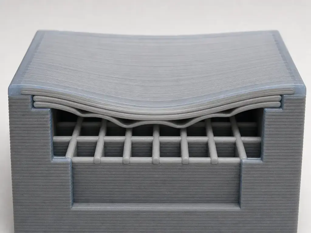
Diagnostic Workflow for Top Layer Gaps 3D Print Problems
Do not change hardware, flow, cooling, and infill all at once. Start with the slicer preview and verify that the top skin is actually solid in the region that failed. OrcaSlicer notes that 0 shell thickness disables the thickness constraint and that 100% surface density is what produces a solid surface, so preview is the fastest way to catch missing top skin, a local modifier, or a wall-adjacent issue before blaming the printer. Cooling behavior also varies by material profile, with Prusa noting that the print fan is not used on the first layer and may start on layers 2 through 4 depending on material. [6] [8]
Central top-face gaps vs wall-edge pinholes vs global under-extrusion
Central top-face gaps usually point first to weak support under the roof. Wall-edge pinholes more often involve shell boundaries or infill/wall overlap, which OrcaSlicer lists separately and suggests starting around 25–30% for that specific overlap control. If gaps appear broadly across the print, not just on upper horizontal faces, remember that Prusa says the printer does not directly sense how much filament actually leaves the nozzle, so an apparent roof defect can mask a wider flow shortfall. [6] [12]
Check in this order:
- Confirm the defect is on upper horizontal surfaces.
- Inspect slicer preview for solid top skin, local modifiers, and top surface density.
- Check top shell thickness in millimeters, not only layer count.
- Compare the defect location with infill cells.
- Check cooling and top-surface speed.
- Check flow or extrusion only if gaps appear broadly, not just on top faces.
- Print a small test coupon before changing a production part.
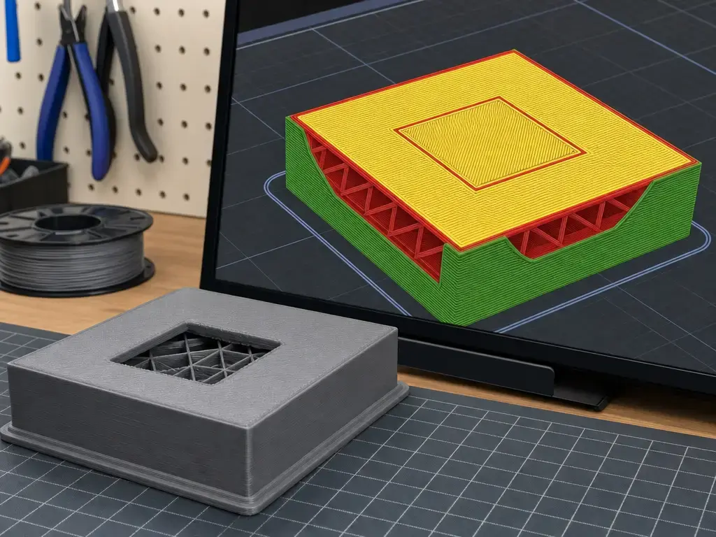
How to Fix Pillowing in 3D Printing
A conservative pillowing fix starts with top shell thickness in millimeters, not with a random jump in infill percentage or flow rate. Simplify3D’s first heuristic is to make sure the solid top section is at least about 0.5 mm thick, while Prusa’s documentation shows why the required top solid layers must scale with layer height instead of staying fixed. If the roof still looks thin or broken, the next priority is support under the top face, because infill is the foundation those upper solid layers are trying to close over. [3] [4] [5]
That is why increasing infill is not always the first or best pillowing fix 3d print users should try. A preview may show that the real problem is top shell thickness, surface density, or a local region that needs more support rather than a denser whole part. Simplify3D suggests escalating from low infill only after top thickness has been checked, and OrcaSlicer separates shell thickness, shell layers, and surface density for the same reason. Very high infill is not a universal cure either, because Creality notes that 80% or 100% infill can create shrinkage-related indentations. For wall-edge gaps, infill/wall overlap is more targeted than a global infill increase, and OrcaSlicer gives 25–30% as a starting point for that control. [4] [6] [7]
After support and top solid layers are sorted, adjust material-appropriate cooling and then slow the top surface or other bridge-like passes if needed. Prusa’s examples are material-specific rather than universal: the fan may start on layers 2–4, PLA may run at 100%, and ASA or ABS may keep the fan off for the first 4 layers before moving to about 15–20%, with some extra bridge cooling. Prusa also recommends lower bridge speed and lower bridge flow when needed, but does not present one fixed setting for every printer, nozzle, or filament. Only if the defect is broad rather than localized should flow rate become the main suspect. In that wider under-extrusion case, Simplify3D’s example is to test an extrusion multiplier change from 1.00 to 1.05, which means 5% more plastic, using a simple 20 mm tall cube with at least 3 perimeter outlines. [8] [9] [10] [11] [12]
| Symptom | Most likely first check | Next step | Avoid first |
|---|---|---|---|
| Holes across broad top face | Top shell thickness in mm. [4] | Add support under the roof. [5] | Immediate flow tuning. |
| Infill pattern visible through top | Top thickness and local support. [3] [4] | Raise support under the top face. [5] | Cranking fan speed only. |
| Gaps near walls only | Infill/wall overlap. [6] | Check shell boundary behavior. [6] | Changing global infill first. |
| Closed but bumpy top | Cooling and bridge-like top speed. [9] [10] | Slow those passes and retest. [10] | Treating it as missing infill everywhere. |
| Gaps everywhere | Broader flow shortfall. [11] [12] | Run a general extrusion check. [11] | Top-only adjustments. |
Slicer Terminology Across PrusaSlicer, Cura, OrcaSlicer, Bambu Studio, and Creality
Different slicers use different labels for closely related settings, which is why a pillowing fix can look inconsistent across software even when the physics is the same. One interface may emphasize top solid layers or top shell layers, another may foreground top or bottom thickness, and another may expose surface density more clearly. The key distinction is between count-based controls and thickness-based controls, because physical roof thickness transfers better across layer heights than a fixed layer count. [3] [4] [6]
Keep these controls separate in your preview and in your settings: shell layers, shell thickness, top surface density, infill/wall overlap, bridge controls, and gap fill are not interchangeable. OrcaSlicer explicitly distinguishes them, including its notes that 0 shell thickness disables that constraint, 100% surface density means a solid surface, and 25–30% overlap is only a starting point for wall-adjacent bonding. Across PrusaSlicer, Cura, OrcaSlicer, Bambu Studio, and Creality, slicer preview is the safest way to verify whether top surfaces are truly solid before changing machine settings. [4] [6]
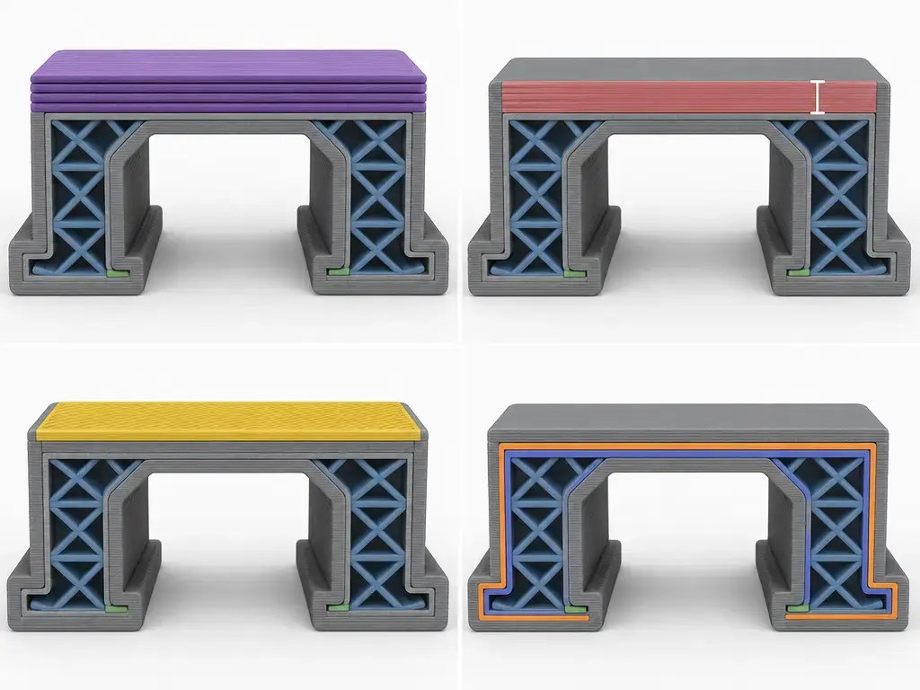
Cooling, Temperature, and Material Limits
Cooling helps bridge-like top passes hold their shape, but fan advice is material-dependent. Prusa’s documentation says the print fan is never used on the first layer, starts on layers 2–4 depending on material, and can look very different between example profiles such as PLA at 100% and ASA or ABS off for four layers and then about 15–20%. Those are examples, not universal settings for every machine or filament. [8]
Temperature, speed, and deposited mass work together rather than one at a time. Prusa’s cooling page says bridges and overhangs should be cooled quickly so the filament freezes in place instead of sagging, while its bridging page recommends lower bridge speed and lower bridging flow when tuning is needed. The 2025 pellet AM study supports that combined view: in its own test setup, sagging changed across 190–200 °C, 45–90 mm/s, 30–60 rpm, and fan on or off conditions, and optimized settings reduced bridge deflection by 64.91%. [9] [10] [14]
No reliable universal fan or bridge value exists here for PETG, PC, TPU, nylon, or filled filaments in general, so this article does not invent one. Geometry also changes the answer: tiny features cool differently from broad flat tops, and enclosed chambers can alter airflow enough that a setting which works on a simple test coupon fails on a wide lid. [8] [9] [10]
When Pillowing Matters Most
Pillowing matters most on visible top faces such as lids, enclosures, trays, signs, sealing surfaces, and parts that will be sanded or painted. On those parts, even a mechanically acceptable print can look unfinished if the roof is thin, wavy, or patterned by the infill underneath.
When It Is Not Pillowing
If the defect is broad, not just on top faces, look first at under-extrusion, clogging, missing top skin in the preview, or too little wall structure. Simplify3D’s under-extrusion guidance treats an extrusion multiplier change from 1.00 to 1.05 as a broader calibration move, not as a top-only cure, and Prusa notes that the printer does not provide direct feedback on how much filament actually leaves the nozzle. That is why a roof problem can sometimes be the first visible sign of a larger flow problem. [11] [12]
Unsupported internal geometry can also masquerade as pillowing. In a 2026 Scientific Reports ceramic FDM study, a first iteration using 5% rectilinear infill showed poor first top-layer deposition and warping by 85% print completion, which points to inadequate internal support rather than a special pillowing-only mechanism. Keep wet filament as a separate diagnosis unless other signs point there, because this article does not have a reliable pillowing-specific moisture threshold to offer. Ironing is also not a structural fix: Prusa describes it as a finishing pass available from PrusaSlicer 2.3.0 and angled 45° to the normal top infill direction. [13] [15]
What Research Says About Sagging and Support
The research view matches day-to-day troubleshooting: a roof span sags when it lacks enough support and when process conditions let the deposited strand stay soft for too long. In the 2025 pellet additive manufacturing study, the test setup examined a 20 mm unsupported span with a 1.2 mm nozzle and varied nozzle temperature, printhead speed, screw speed, and fan activation. Within that study, forced cooling and higher printhead speed were associated with a 64.91% reduction in bridge deflection under optimized conditions. [14]
That does not mean those numbers should be copied into desktop PLA, PETG, or ABS profiles. It means sagging depends on span, heat, cooling, and deposited material flow together. The ceramic FDM study makes the same point from another angle: its first 5% rectilinear infill iteration left the first top layer poorly supported, and by 85% completion the part showed warping and poor top-layer deposition. Use those studies as mechanism evidence, not as universal slicer recipes. [14] [15]
Conclusion: How to Prevent Pillowing in 3D Printing
To prevent pillowing in 3d printing, check top shell thickness first, support under the top skin second, and cooling or speed third. Top solid layers are closing a roof over infill, so they need enough physical thickness and enough internal support to succeed. Cooling advice is material-dependent, and flow calibration belongs later in the process because a wider extrusion shortfall can mimic a top-only defect. [3] [4] [5] [8] [11] [12]
FAQ
What causes pillowing in 3D printing?
Pillowing usually starts when the first top solid layers have to span infill that does not support them well enough. Too little physical top thickness, sparse support under the roof, weak cooling on bridge-like passes, or overly hot and slow deposition can all contribute. Under-extrusion can create a similar look, which is why top defects should be separated from broader flow problems before you change settings. [3] [4] [5] [9] [12]
How do I fix pillowing in 3D printing?
Start with top shell thickness in millimeters, then improve support under the top face, then tune cooling and speed if needed. That order is more reliable than jumping straight to a higher infill percentage, a higher fan speed, or a flow rate change. If the defect is only near walls, target overlap or shell behavior instead of treating it like central roof sag. [4] [5] [6] [8] [10]
How do I fix top layer gaps 3D print problems without wasting material?
Use the low-waste path first: inspect slicer preview, increase top thickness before global infill, and use local support changes where the roof actually needs them. Infill supports the roof, but more infill everywhere is not always the best answer, and very high infill can create its own surface artifacts in some cases. [4] [5] [7]
Is pillowing the same as under-extrusion?
No. Pillowing is usually localized to upper horizontal surfaces where the roof is closing over infill, while under-extrusion is a broader shortage of deposited material that can show gaps in many regions. Prusa explicitly notes that the printer does not directly measure the actual filament leaving the nozzle, so a top defect can hide a wider flow shortfall, but that still does not make the two diagnoses identical. [3] [11] [12]
How many top solid layers do I need to stop pillowing?
There is no universal count. Prusa gives at least 3 top layers as a source-based example and shows that 3 top layers at 0.3 mm and 9 top layers at 0.1 mm can represent a similar physical thickness, while Simplify3D suggests thinking first in terms of about 0.5 mm of solid top section. The safer rule is thickness first, count second. [3] [4]
Can ironing fix pillowing?
Not by itself. Ironing can smooth a top surface that is already mostly closed, but it does not add missing support under the roof and it does not correct a wider extrusion problem. Prusa describes ironing as a finishing pass available from PrusaSlicer 2.3.0, angled 45° relative to the normal top infill direction. [13]
Should I use bridge settings or fan changes for a pillowing fix?
Sometimes, but not as your first move and not with one universal number. Bridge speed, bridge flow, and fan behavior are material- and geometry-dependent, so they are best used after top thickness and internal support are already reasonable. Prusa’s guidance supports faster cooling for bridge-like spans and lower bridge speed or flow when tuning is needed, but it does not offer one fixed recipe for every material. [8] [9] [10]
Related on 3D Mag
- 3D Printing Ghosting: Causes and Fixes
- Over Extrusion in 3D Printing: Causes and Fixes
- Heat Creep in 3D Printing: Causes, Clogs, Fixes
Sources
- [1] ISO/ASTM 52900:2021 — Additive manufacturing — General principles — Fundamentals and vocabulary. https://www.iso.org/standard/74514.html
- [2] NIST IR 8059 — Materials Testing Standards for Additive Manufacturing of Polymer Materials. https://nvlpubs.nist.gov/nistpubs/ir/2015/NIST.IR.8059.pdf
- [3] Prusa Knowledge Base — Layers and Perimeters. https://help.prusa3d.com/article/layers-and-perimeters_1748
- [4] Simplify3D — Gaps in Top Layers. https://www.simplify3d.com/resources/print-quality-troubleshooting/gaps-in-top-layers/
- [5] Prusa Knowledge Base — Infill. https://help.prusa3d.com/article/infill_42?product=sl1
- [6] OrcaSlicer Wiki — Top and Bottom Shells. https://github.com/OrcaSlicer/OrcaSlicer/wiki/strength_settings_top_bottom_shells
- [7] Creality Wiki — Infill. https://wiki.creality.com/en/software/update-released/Strength/infill
- [8] Prusa Knowledge Base — Print Fan Is Not Spinning. https://help.prusa3d.com/article/print-fan-is-not-spinning_2081
- [9] Prusa Knowledge Base — Cooling. https://help.prusa3d.com/article/cooling_127569?product=mmu3
- [10] Prusa Knowledge Base — Poor Bridging. https://help.prusa3d.com/article/poor-bridging_1802?product=mk3-5
- [11] Simplify3D — Under-Extrusion. https://www.simplify3d.com/resources/print-quality-troubleshooting/under-extrusion/
- [12] Prusa Knowledge Base — Under-extrusion. https://help.prusa3d.com/article/under-extrusion_2007?product=mk2-5s
- [13] Prusa Knowledge Base — Ironing. https://help.prusa3d.com/article/ironing_177488
- [14] MDPI Polymers — Physics-Based Predictive Modeling of Gravity-Induced Sagging in Support-Free Pellet Additive Manufacturing. https://www.mdpi.com/2073-4360/17/21/2858
- [15] Scientific Reports — Process parameter optimization for alumina ceramic parts manufactured by fused deposition modelling. https://www.nature.com/articles/s41598-026-36153-6