
Summary
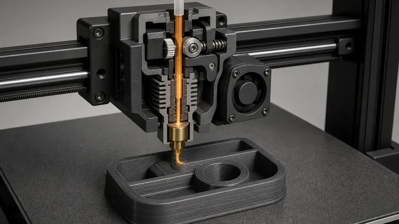
Fused filament fabrication is a filament-based 3D printing process in which thermoplastic feedstock is heated, forced through a nozzle, and deposited layer by layer to build a part from digital model data. In ISO/ASTM language, it sits within additive manufacturing and, more specifically, within material extrusion, the process family in which material is selectively dispensed through a nozzle or orifice. [2]
That framing matters because fused filament fabrication is more than “melt plastic and stack layers.” The process runs from model preparation to slicing, G-code generation, motion planning, extrusion, cooling, and part removal. Final results depend on software, mechanics, temperature control, material condition, and measurement method. This is why broad claims about universal speed, accuracy, or strength are unreliable: standards define the process family, but outcomes still depend on the machine, material, geometry, profile, and test method used. [2] [4] [11] [16]
What Is Fused Filament Fabrication?
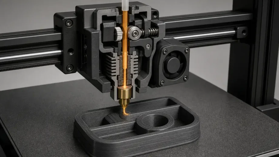
Fused filament fabrication is a 3D printing process in which solid thermoplastic filament is fed into a heated print head, softened or melted, and extruded through a nozzle to form a part layer by layer. In common practice, the filament is supplied on a spool, and the two most common nominal diameters in vendor documentation are 1.75 mm and 2.85 mm, although a given printer is usually designed around one feedstock format rather than both. [9]
Physically, the printer lays down narrow extruded strands, often called roads or beads, onto a build surface and then onto earlier layers. Those strands bond as they cool, so the object is built from many controlled extrusions rather than cast as one mass. That makes FFF simple to describe but sensitive in practice: flow rate, nozzle temperature, layer timing, and cooling all influence whether adjacent roads fuse well or instead produce weak interfaces, sagging, stringing, or warping. [9] [11] [22]
FFF is also a control problem. A slicer converts geometry into machine instructions, commonly G-code, and firmware turns those commands into planned motion and extrusion events. Marlin’s documentation describes a movement flow from G-code to segmented move to planner queue to stepper interrupt service routine, a useful reminder that the printer does not execute a CAD model directly. It executes a stream of motion and material commands. [7] [12]
Core elements of an FFF 3D printer
- Filament feedstock, usually thermoplastic on a spool. [9]
- Extruder drive that pushes filament toward the melt zone. [7]
- Hot end that heats the material for extrusion. [7]
- Nozzle that meters the deposited bead. [9]
- Motion system that moves the toolhead, the bed, or both. [12]
- Build plate or build surface for first-layer support and adhesion. [2]
- Controller and firmware that execute the print job. [12]
- Slicer-generated G-code or similar machine instructions. [7] [12]
- Cooling system, where fitted, to control solidification and overhang behavior. [11]
- Sensors for temperature, position, probing, or other feedback, depending on the machine. [12]
Where FFF Fits in ISO/ASTM Taxonomy (Material Extrusion / MEX)
Material extrusion, or MEX, is the ISO/ASTM process category. FFF is a common filament-based term used within that category. [2]
ISO/ASTM 52900:2021 is the main vocabulary reference for additive manufacturing terminology, and the ISO listing shows that the current edition was published in November 2021 and confirmed as current in 2025. [1] In the preview text, material extrusion is defined as the additive manufacturing process in which material is selectively dispensed through a nozzle or orifice. [2]
So FFF is a process label used within MEX, not a separate top-level ISO/ASTM category. ISO/ASTM 52900 also lists seven process-category abbreviations: BJT, DED, MEX, MJT, PBF, SHL, and VPP. [2] “FFF” is useful when discussing filament-fed systems specifically, but the standardized family name is material extrusion. [1] [2]
| Term | What it means | Standardized? | Notes |
|---|---|---|---|
| Material extrusion (MEX) | ISO/ASTM process category for AM by selective dispensing through a nozzle or orifice. [2] | Yes. [1] | Broad taxonomy term. [2] |
| FFF | Common generic term for filament-based material extrusion. [6] [7] | Not as a top-level ISO/ASTM category. [2] | Useful when discussing spool-fed filament systems. [9] |
| FDM | Stratasys trademark used for the same basic physical principle. [5] | No as a generic standards category. [2] | Brand-specific legal term in origin. [5] [6] |
| Pellet/granulate extrusion | Material extrusion using pellets or granulate rather than filament. [3] | Within MEX broadly, but not classic filament FFF. [2] [3] | Feed path and process tuning differ from spool-fed filament systems. [3] |
FFF vs FDM: Is FFF the Same as FDM?
In physical operation, FFF and FDM describe the same basic principle: a thermoplastic feedstock is heated and extruded layer by layer to build a part. The meaningful difference is terminology, trademark status, and ecosystem usage, not a different physics model. [5] [6]
Stratasys’ legal information page lists FDM as a trademark, and WIPO notes that Stratasys took out a trademark on the term “FDM” on January 28, 1991. WIPO also notes that other manufacturers use alternative generic labels such as “fused filament fabrication” and “thermoplastic extrusion” for the same process family. [5] [6] RepRap’s glossary gives the community version of that history: FFF was coined to provide a legally unconstrained generic term. [7]
In everyday conversation, many people use the two terms interchangeably. In technical writing, FFF is usually the better generic label unless the subject is specifically Stratasys branding, product lines, or documentation. [5] [6] One practical caution follows: controls, validation practices, or qualification contexts associated with industrial branded FDM systems should not be assumed to apply automatically to every generic FFF printer. [5] [16]
How the FFF Printing Process Works (From Model to Part)
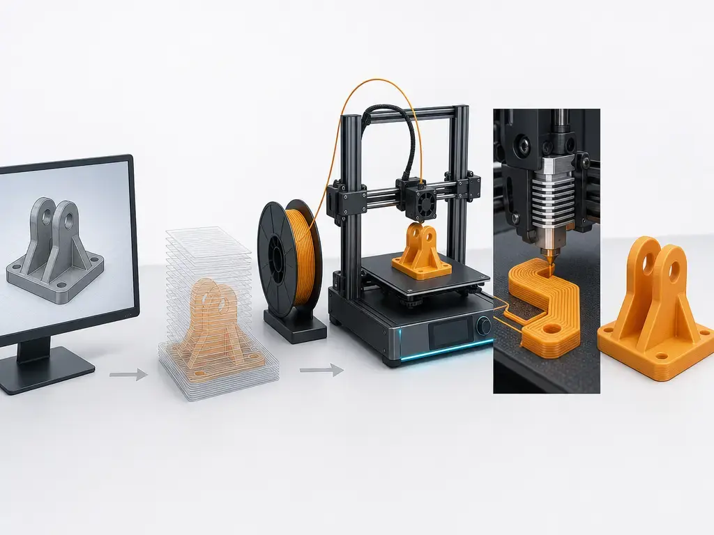
The FFF printing process starts with a 3D model and ends with a cooled, removable part, but several translation steps sit in between. The model is prepared, sliced into layers, turned into motion and extrusion instructions, executed by firmware, and then realized as deposited polymer on a build surface. Because FFF uses filament rather than liquid resin or powder, the process depends on continuous feed, melting, deposition, and cooling rather than vat curing or powder fusion. [9] [11] [12]
Slicing is where manufacturing strategy enters the workflow. The slicer decides layer height, line width assumptions, wall count, infill, support generation, temperatures, speeds, retractions, and cooling commands, then exports that plan as G-code or another machine-readable command stream. In the NIST paper’s example configuration, one PrusaSlicer table shows 215 °C filament temperature, 15 mm³/s maximum volumetric speed, 0.2 mm layer height, 45 mm/s perimeter speed, and 80 mm/s infill speed, but those numbers are explicitly an example configuration rather than a universal recommendation. [11]
Firmware then has to turn that command stream into real motion. Marlin’s documentation shows that movement commands pass through segmentation and a planner queue before stepper timing is generated, and it notes that actual speed depends on acceleration limits and how far the machine can move before changing direction. [12] That is why a headline motion speed alone says very little about print quality. Feature speed, travel speed, acceleration, and the hot end’s melt capacity all interact. [11] [12]
A useful control term here is volumetric flow rate, meaning how much plastic the hot end can melt and deliver per unit time. A file can command high head speed, but if the required material volume exceeds what the nozzle and hot end can sustain, output quality suffers through under-extrusion, poor bonding, or unstable flow. [11]
Basic FFF printing workflow
- Create or import a 3D model. [2]
- Orient the part and choose process settings in a slicer. [11]
- Slice the geometry into layers and generate toolpaths. [11]
- Export G-code or equivalent machine instructions. [7] [12]
- The printer firmware interprets those commands and plans motion. [12]
- Filament is heated, extruded, and deposited bead by bead and layer by layer. [9] [22]
- The part cools, is removed from the build plate, and may then be cleaned up or post-processed. [22]
FFF Printer Technology and Main Subsystems (What Limits Results)
An FFF printer is best understood as a melt-delivery system, a motion system, and a thermal-management system. The extruder drive must feed filament consistently, the hot end must supply enough heat to plasticize it, and the nozzle must meter it into a bead that matches the toolpath assumptions closely enough for the part to form as intended. [11] [12]
Nozzle diameter strongly affects practical feature scale and throughput, but it is not a stand-alone accuracy number. Layer height also has to stay in a workable relation to nozzle size. Prusa’s documentation gives a practical guideline that layer height should stay below 80% of nozzle diameter, with a 0.4 mm nozzle giving about 0.32 mm as a maximum example. [10] That is a process guideline, not a law of nature, and it does not mean a 0.4 mm nozzle automatically produces 0.4 mm accurate features. [10] [16]
The motion system adds another set of limits. Marlin documents that commands are segmented, queued, accelerated, and then turned into stepper pulses, with lookahead used to set entry and exit speeds for queued moves. [12] Corners, curves, short segments, and frequent direction changes therefore behave differently from long straight paths. This helps explain why a printer can have fine nominal step resolution but still show ringing, corner rounding, or inconsistent extrusion on small features. [12]
The build plate and enclosure manage thermal gradients. First-layer adhesion, shrinkage stress, and layer-to-layer temperature history all change when the bed, chamber, and surrounding air are controlled more tightly. As a device-specific example, the UltiMaker Factor 4 Plus lists a 330 x 240 x 300 mm build volume, 60 to 400 micron layer resolution, 0.25/0.4/0.6/0.8 mm nozzle diameters, and a 180 to 340 °C nozzle temperature range, but those figures describe the machine’s envelope, not guaranteed part quality. [20]
Materials Used in FFF 3D Printing (and Why They Behave Differently)
FFF uses thermoplastic feedstocks, but that category is too broad to predict print behavior by itself. Material choice changes viscosity, shrinkage, interlayer bonding, cooling needs, moisture sensitivity, and the likelihood of warping or support problems. [14] [22]
PLA is commonly chosen for easier printing and visual prototypes, while PETG often sits between printability and tougher end use. A vendor-specific PETG example from Bambu Lab lists 230 to 260 °C nozzle temperature, 65 to 75 °C bed temperature, 35 to 50 °C chamber temperature, supported nozzle sizes from 0.2 to 0.8 mm, and speed guidance below 200 mm/s. [14] Those figures are not universal PETG rules; they show that even within a familiar filament family, processing windows are material- and vendor-specific. [14]
ABS and ASA usually need tighter thermal control because shrinkage and warpage are bigger concerns. TPU and other flexible filaments introduce feeding and retraction challenges because the material can deform in the feed path before it reaches the nozzle. Nylon (PA) is valued for toughness and wear behavior, but in practice its moisture sensitivity makes drying and storage part of process control. PC raises thermal demands further and is usually chosen only when the application justifies the added process difficulty. [17] [22]
A major reason materials behave differently is the distinction between amorphous and semi-crystalline polymers. The polyolefins review explains that warpage results from shrinkage on cooling, and that semi-crystalline polymers can experience extra shrinkage because crystallization produces a denser phase than the amorphous state. [22] That extra shrinkage promotes internal stress and warping, which helps explain why not all polymers tolerate open-frame, room-temperature printing equally well. [22]
Composites add more complexity. Carbon-fiber- and glass-fiber-filled filaments can raise stiffness or alter creep behavior, but the filler can also abrade the print path. A 2025 review notes that nozzle wear is a common issue with carbon fiber and glass fiber composites, especially with standard brass nozzles, and that hardened or other wear-resistant nozzles are commonly recommended. [21] Support materials are a separate category again: in material-extrusion systems, support material can differ from the part material and may be deposited from a separate nozzle or print head. [2]
Performance and Metrology: Accuracy, Precision, Resolution, Tolerance, Strength
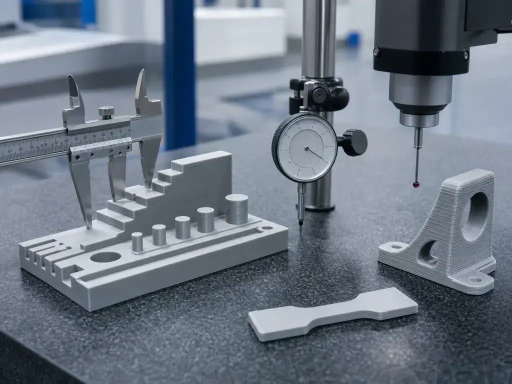
No reliable universal FFF accuracy or tolerance figure was found. The main reason is methodological: a 2022 systematic review identified 127 experimental studies and concluded that prior work is not widely generalisable, that each study has a specific experimental setup, and that no clear consensus exists on optimal parameter values across the most important printing parameters. [16]
That is why standards frame performance through artefacts and measurement procedures rather than through a single marketing number. ISO/ASTM 52902:2023 covers benchmarking test piece geometries and associated measurements for AM system capability evaluation and calibration, but it does not prescribe one universal machine-setting recipe. [4] Dimensional claims therefore need to be tied to an artefact, a measurement method, a machine state, and a material condition. [4] [16]
| Quantity | Depends on… | What it means in practice |
|---|---|---|
| Accuracy | Geometry, material, profile, and measurement method. [4] [16] | Closeness to the intended dimension. [4] |
| Precision / repeatability | Machine state, calibration, environment, and feedstock condition. [4] [16] | How consistently the same setup reproduces a result. [4] |
| Resolution (practical XY/Z) | Nozzle diameter, extrusion width, layer height, path planning, and motion behavior. [10] [12] | Smallest practical feature scale, not a guarantee of dimensional truth. [10] |
| Tolerance | Design allowance, process control, and verification method. [4] [16] | Acceptable deviation for a specific feature or part. [4] |
| Surface finish | Layer height, path strategy, cooling, and material response. [10] [22] | Visible texture and stepping, especially on curves and slopes. [10] |
| Strength | Orientation, infill, bead bonding, geometry, and test method. [13] [23] | Printed-part mechanical behavior, not just base polymer data. [13] |
Resolution is especially easy to misunderstand. Smaller layers can reduce visible stair-stepping, and smaller nozzles can make narrower extrusions possible, but neither guarantees better dimensional accuracy across all geometries. Even filament control figures can mislead if taken out of context: Prusa’s Prusament PLA page claims ±0.02 mm manufacturing precision for the filament itself, which is a feedstock consistency claim, not a printed-part tolerance claim. [15]
Mechanical properties also have to be separated into feedstock properties and printed-part properties. The UltiMaker PLA TDS reports orientation-specific tensile stress at break values for printed samples of 45.5 ± 1.1 MPa in XY, 56.0 ± 1.5 MPa in YZ, and 33.1 ± 2.8 MPa in Z, with notes stating the samples were printed on an Ultimaker S5 Pro bundle at 0.15 mm layer height, with an AA 0.4 print core, 100% infill, and Cura 4.9, and tested by ASTM D3039. [13] Those figures are useful precisely because they are specific. They show anisotropy and method dependence, not a universal “PLA strength.” [13] More generally, ASTM D638-22 remains a standard test-method anchor for tensile properties of plastics, reinforcing the point that published strength numbers only mean something when the method is stated. [23]
The practical conclusion is straightforward: measure the part you care about, using the geometry, material, and profile you actually plan to use. FFF metrology is application-specific. [4] [16]
Design and Slicing Choices That Change Outcomes (Without “Magic Settings”)
Design choices enter the process before the printer moves. Orientation changes where supports are needed, which faces show stepping, and how loads cross layer boundaries. A bracket printed flat and the same bracket printed upright may use the same material and machine but behave differently in strength, surface finish, and support scarring because their toolpaths and thermal histories differ. [11] [13] [16]
Perimeters, infill, and first-layer strategy matter for similar reasons. More walls can stiffen thin parts differently from adding more infill, while support need depends on geometry, orientation, material response, and cooling rather than on one fixed angle rule. First-layer choices also matter disproportionately because poor bed contact can cascade into shifting, curling, or failed builds. [10] [22]
Lower layer height is one of the most common “improve quality” suggestions, but it is not a magic setting. Prusa’s nozzle-height guideline shows that layer height is constrained by nozzle size, and the review literature shows no clear universal parameter recipe across machines and materials. [10] [16] Smaller layers may improve visible stepping on curved surfaces, but they also increase build time and can change thermal history, bonding behavior, and sensitivity to flow limits. [11] [16]
Types of FFF Printers and Adjacent Material-Extrusion Variants
Not every material-extrusion printer operates the same way, even within the same broad process family. MEX is the standardized umbrella, but machine architecture, enclosure strategy, tool count, and feedstock form all change what a printer can do reliably. [2]
| Variant | Feedstock | Typical use | Boundary note |
|---|---|---|---|
| Desktop FFF | Filament spool. [9] | Prototypes, hobby use, light functional parts. [9] | Usually the least controlled thermal environment. [9] |
| Enclosed/pro FFF | Filament spool. [20] | Engineering materials, longer runs, better thermal control. [20] | Better capability envelope does not equal universal part accuracy. [20] |
| Multi-material FFF | Two or more filament paths or toolheads. [2] | Color changes, soluble supports, mixed-material work. [2] | Adds purge, alignment, and contamination concerns. [2] |
| Pellet/large-format extrusion | Pellets or granulate. [3] | High-throughput or large-format extrusion builds. [3] | Related MEX, but not classic filament FFF. [2] [3] |
A professional enclosed machine can have a very different operating envelope from an open desktop machine. The UltiMaker Factor 4 Plus example is useful only as an illustration that spec ranges vary widely across systems, not as proof of what FFF printers do in general. [20] The key boundary is that pellet-fed extrusion is adjacent material extrusion, but it is not simply FFF with bigger parts, and settings or results should not be treated as interchangeable. [2] [3]
Limitations, Defects, and Safety Considerations
Common defects and why they happen
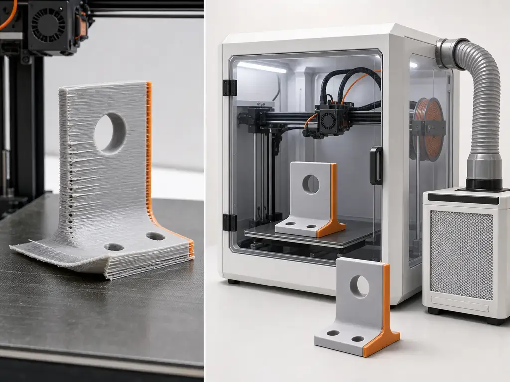
FFF defects are often consequences of heat flow, shrinkage, moisture, and flow mismatch rather than isolated machine failures. Warping, corner lift, stringing, under-extrusion, over-extrusion, and layer separation all reflect some mismatch among toolpath, temperature, material condition, and cooling behavior. [11] [22] The polyolefins review is especially clear that warpage results from shrinkage on cooling, and that semi-crystalline polymers can warp more because crystallization adds extra shrinkage beyond simple thermal contraction. [22]
Moisture is another recurring variable. Wet filament can destabilize extrusion and degrade surface quality, and materials differ widely in how strongly they respond to water uptake. Even when a part looks acceptable, anisotropy remains a structural limitation because layer interfaces and raster directions matter mechanically. Support interfaces can also leave marks or dimensional artefacts, which is one reason support strategy has to be treated as a design choice rather than an afterthought. [13] [17]
Emissions and exposure control (what safe looks like)
Indoor safety should not be reduced to “PLA is safe” or “ABS is unsafe.” EPA states that 3D printing can release VOCs and ultrafine particles in the 1 to 100 nm size range, and notes that different filaments release different amounts of respirable particles. EPA also notes that additives and filament extruders can introduce additional exposure concerns. [19]
NIOSH offers a more useful framework because it treats control hierarchically. First, consider source and context: use lower-emission materials when they fit the task, and note that NIOSH cites studies in which ABS produced higher airborne ultrafine particle concentrations than PLA. [17] Second, use engineering controls such as enclosures, local exhaust ventilation, and filtration. NIOSH cites studies in which a filtered enclosing hood reduced particle emissions by 97% to 99%, and an enclosure plus LEV and HEPA-filtered exhaust reached a 99% reduction in one cited setup. [17] Third, manage room placement and occupancy by keeping printers away from densely occupied areas and avoiding unnecessary time near running machines. [17] [19]
UL 2904 adds an important standards point. The ANSI listing describes UL 2904 Ed. 2-2023 as a method for testing and assessing particle and chemical emissions from 3D printers under defined indoor use conditions, including classroom, office, and residential scenarios. [18] That matters because it gives industry a common emissions characterization method. It does not mean a printer is universally safe in every room, with every material, at every temperature setting. [17] [18]
Historical Background
The core process behind modern filament printing is older than the desktop boom. Google Patents lists S. Scott Crump on US5121329A, “Apparatus and method for creating three-dimensional objects,” with a priority and filing date of October 30, 1989. [8] That patent is a useful historical anchor for the technology later commercially associated with fused deposition modeling. [8]
The naming split came later. WIPO notes that while the underlying patent position changed over time, manufacturers other than Stratasys could not refer to the technique as fused deposition modeling because of the trademark, and instead used terms such as fused filament fabrication or thermoplastic extrusion. [6] RepRap’s glossary records the open-source community rationale directly: FFF was adopted as a generic, legally unconstrained label for the process. [7]
Current Research and Standards Context
The standards landscape is fairly clear about what has been formalized. ISO/ASTM 52900:2021 provides core terminology for additive manufacturing and its process categories, ISO/ASTM 52903-1:2020 addresses feedstock materials for plastic material extrusion, and ISO/ASTM 52902:2023 covers benchmark artefacts for geometric capability assessment and calibration. [1] [3] [4] For emissions testing, UL 2904 Ed. 2-2023 provides a method for characterizing particle and VOC emissions from operating printers in indoor environments. [18]
Research, however, still centers on parameter discovery and transferability rather than on a universal process recipe. The 2024 NIST paper focuses on online measurement for parameter discovery in FFF, and the 2022 systematic review shows why that work matters: the literature remains hard to generalize across machines, materials, artefacts, and slicer assumptions. [11] [16] Standards can define vocabulary, feedstock framing, test artefacts, and emissions methods, but they do not remove the need for print-specific validation. [3] [4] [16]
What Fused Filament Fabrication Is Best For
Fused filament fabrication is best suited to cases where direct-from-CAD production, low tooling cost, and fast iteration matter more than perfect isotropy or tightly certified geometry. That makes it useful for prototypes, jigs, fixtures, visual models, simple enclosures, and selected functional parts whose performance can be checked quickly and revised cheaply. At the same time, the research record and printed-part test data argue against overgeneralization: dimensional results are not broadly generalisable across setups, and strength can vary strongly with print orientation and method. For load-bearing, safety-critical, or tightly toleranced work, the right approach is to print, measure, test, and validate the exact configuration you intend to use. [13] [16]
FAQ About Fused Filament Fabrication
What is fused filament fabrication (FFF) in 3D printing?
FFF is a filament-based form of material extrusion in which thermoplastic feedstock is heated and deposited through a nozzle to build a part layer by layer from digital model data. In ISO/ASTM language, the standardized family name is material extrusion, or MEX, while FFF is the widely used generic term for the filament-fed branch most people associate with desktop and professional spool-based printers. [2] [6] [9]
FFF vs FDM: are they the same process, and why do both terms exist?
They describe the same basic physical process, but not the same naming context. FDM is a Stratasys trademark, while FFF became the generic term used by others, including the RepRap community, to discuss the process without using the trademarked label. The difference is legal and linguistic more than technical, even though people often use the two interchangeably in casual conversation. [5] [6] [7]
How does the FFF printing process work from CAD file to printed part?
A model is prepared in CAD or imported, then sliced into layers and toolpaths. The slicer outputs G-code or a similar instruction stream, and firmware turns those commands into planned motion and extrusion. The printer feeds filament into the hot end, extrudes a bead through the nozzle, deposits it on the build surface or previous layer, and repeats the cycle until the part is complete and cool enough to remove. [11] [12]
What limits “resolution” in FFF: layer height, nozzle diameter, or extrusion width?
All three matter, along with motion behavior and material flow. Nozzle diameter influences practical bead size, layer height influences vertical stepping and bonding behavior, and extrusion width reflects how the slicer and melt behavior realize the toolpath. Prusa’s guideline that layer height should stay below about 80% of nozzle diameter is useful, but it is still only one process guideline. Resolution in practice is a system outcome, not a single spec line. [10] [12] [16]
Why can’t FFF printers be assigned a single universal accuracy or tolerance?
Because the literature does not support it. The 2022 systematic review covered 127 studies and found poor generalisability and no clear consensus on optimal parameter values across setups. Geometry, material, slicer assumptions, machine state, and measurement method all change the answer. A printer can also use tightly controlled filament, such as a product claiming ±0.02 mm filament precision, without that implying anything universal about printed-part dimensions. [15] [16]
What’s the safest way to run an FFF printer indoors (classroom/home/makerspace)?
Use a controls hierarchy. Start by choosing lower-emission materials when they are fit for purpose, then add engineering controls such as an enclosure, local exhaust ventilation, and appropriate filtration, and finally manage placement and time spent near operating machines. NIOSH supports this approach, and UL 2904 matters because it provides a standard emissions characterization method, though not a universal room-safety guarantee for every printer-material combination. [17] [18] [19]
Sources
- ISO — ISO/ASTM 52900:2021 listing (Fundamentals and vocabulary)
- ISO/ASTM 52900:2021 sample PDF (iTeh preview; includes process-category definitions incl. MEX)
- ISO — ISO/ASTM 52903-1:2020 listing (MEX plastics feedstock materials)
- ISO — ISO/ASTM 52902:2023 listing (test artefacts; geometric capability assessment)
- Stratasys — Legal information (trademark statement)
- WIPO — World Intellectual Property Report 2015 (mentions “fused filament fabrication” and FDM trademark context)
- RepRap Wiki — Glossary
- Google Patents — US5121329A
- UltiMaker — Comparing FFF, SLA, and SLS technologies
- Prusa Knowledge Base — Layers and perimeters
- NIST — Online Measurement for Parameter Discovery in Fused Filament Fabrication
- Marlin Firmware docs — Code structure
- UltiMaker PLA Technical Data Sheet v2.00
- Bambu Lab — PETG Basic Technical Data Sheet
- Prusa — Prusament PLA product page
- Heliyon systematic review on dimensional accuracy in FFF
- NIOSH/CDC — Approaches to Safe 3D Printing
- ANSI Webstore — UL 2904 Ed. 2-2023 listing
- US EPA — 3D Printing Research at EPA
- UltiMaker — Factor 4 Plus spec page
- Materials — Review on composite filament materials
- Polymers — Additive Manufacturing of Polyolefins review
- ASTM — D638-22 listing (Tensile Properties of Plastics)