
Summary
Terrestrial photogrammetry explained: a ground-based way to turn overlapping photos into 3D geometry and measurements. The camera does not directly range to the object the way a laser scanner does. Instead, software estimates camera poses, tie points, and scene structure from image relationships. In that sense, ground based photogrammetry is image-derived measurement, not direct distance sensing. [2] [3]
Outputs can include a sparse point cloud, dense point cloud, mesh, texture, and a scaled or georeferenced model. Accuracy is a workflow outcome, not an automatic result of taking many photos. If real dimensions matter, scale bars, control points, and independent check points are what turn a plausible model into a defensible one. Capture geometry, calibration stability, scene texture, and reporting all affect the result. [2] [3]
Terrestrial Photogrammetry Explained (What It Is — and Isn’t)
Photogrammetry is often described as the “art and science” of obtaining measurements from photographs. [1] In terrestrial photogrammetry, those measurements are made from a fixed terrestrial location rather than from aircraft or satellites. [2] In plain terms, ground based photogrammetry means taking overlapping photos from the ground, then solving the object’s shape, size, and position from image geometry.
It is not the same as aerial or UAV photogrammetry, because the platform and viewing geometry differ. It is also not the same as terrestrial laser scanning, which is an active ranging method, or structured-light and phone LiDAR systems, which emit or project energy to sample geometry directly. Terrestrial photogrammetry is passive and image-driven: the camera records texture and perspective, and reconstruction comes later from matching and triangulating features across views.
The terms also overlap with close-range photogrammetry, but they are not identical. One textbook classification defines terrestrial photogrammetry by platform or location and close-range photogrammetry by imaging distance, commonly with object distance below about 300 m. [2] The same source notes that there is no hard-and-fast definition for close-range photogrammetry, so the label shifts by discipline and project type. [2] In practice, ground photogrammetry and close range photogrammetry often describe the same family of work from different angles.
Quick Compare: Terrestrial Photogrammetry vs Terrestrial Laser Scanning (TLS)
Terrestrial photogrammetry is passive and image-based, while TLS is active and measures ranges directly. In practice, photogrammetry depends on overlap, texture, and network geometry, whereas TLS instruments are published with example specifications for range, field of view, speed, and point-accuracy conditions. Those vendor figures are instrument-level examples, not the same thing as scan registration quality or final project accuracy. [12] [13]
| What it measures | Best at | Primary gotchas |
|---|---|---|
| Photogrammetry infers 3D from images | Texture, color, flexible viewpoints | Needs texture, scale/control, and QC |
| TLS measures ranges and angles directly | Fast geometric capture, low-texture surfaces | Specs are not the same as project accuracy |
Where “Terrestrial,” “Close-Range,” and “Ground-Based” Overlap
These terms overlap because they often describe the same field workflow. “Terrestrial” points to where the camera is located: on the ground, at a fixed terrestrial location. [2] “Close-range” usually points to a distance regime instead, with under about 300 m used as a common convention rather than a strict boundary. [1] [2]
That is why ground based photogrammetry can cover several setups: a tripod circuit around a façade, a handheld interior survey, or a mast or pole camera used from the ground. In each case, the method is terrestrial because imaging is ground-based, but the object distance, control strategy, and geometry may differ. The useful distinction is platform/location versus distance regime, not rigid vocabulary.
How It Works (Images → Camera Poses → 3D)
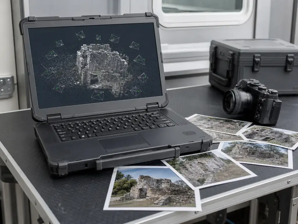
Structure from motion (SfM) is the analysis of multiple images of the same subject from different angles to derive 3D geometrical information that is not inherent in a single image. [7] In a terrestrial workflow, overlapping photos provide repeated views of the same visual features. Software matches those features across images as tie points, estimates camera poses, and builds a first sparse reconstruction of the scene. [3] This alignment stage produces a tie point cloud and a set of camera positions that support later depth-map and surface reconstruction. [3]
Classical close-range workflow descriptions place control points or scaling lengths in the same chain as image measurement and bundle adjustment. [2] Bundle adjustment is the global refinement step: it adjusts camera orientation, position, and internal calibration so the image observations fit the 3D geometry as consistently as possible. In practical terms, the solver balances intrinsics, extrinsics, and object points together. Good viewpoint diversity and stable camera behavior help keep that solution believable. [2] [3]
After alignment, dense reconstruction fills in more surface detail from the solved camera network. The sparse tie point cloud is not usually the final deliverable; it is the scaffold that leads to denser products such as a dense point cloud, mesh, texture, DEM, or orthomosaic, depending on project type. [3]
The following core terms are used consistently in close-range workflow descriptions and software manuals. [2] [3]
| Term | One-line definition |
|---|---|
| Tie points | Repeated image features used to connect photos geometrically |
| Sparse cloud | The initial low-density 3D structure from image alignment |
| Dense cloud | A denser surface reconstruction computed after alignment |
| Camera calibration / intrinsics | Internal lens and sensor parameters used to model image formation |
| Exterior orientation / pose | The camera’s position and orientation in space |
| Control point | A known object-space reference used to constrain the model |
| Check point | A known reference held back for validation rather than fitting |
| Scale bar | A known distance used to set or verify model scale |
| Orthomosaic / orthophoto | An orthographic image product generated from solved geometry |
Ground-Based Capture Workflow (Practical, Non-Software-Specific)
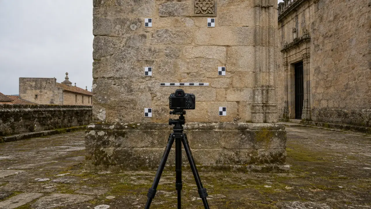
A good terrestrial photogrammetry workflow starts with the deliverable, not the shutter button. A textured mesh for visualization, a measured façade, a stockpile volume, and an orthographic product do not all need the same viewpoints or control strategy. The key planning idea is not raw image count but geometry: enough overlap, enough parallax, and enough viewpoint diversity for the solver to triangulate shape reliably. Classical workflow descriptions therefore include control points or scaling lengths as part of building a usable object coordinate system, not as an afterthought. [2]
Once images are captured, the project should move from alignment to review, then to denser products, then to validation. That order matters because dense reconstruction can make a weak network look convincing. If the job is measurement-oriented, the plan should already define how scale or georeferencing will be introduced, which points will be reserved as independent checks, and what uncertainty will be reported at the end. [2] [3]
- Plan deliverables and geometry — define the target output, required detail, access limits, and reference strategy before capture.
- Capture overlapping images — record the subject from multiple viewpoints with enough baseline variety to support reconstruction.
- Align the image set — estimate camera poses and build the initial sparse scene model. [3]
- Review the sparse reconstruction — inspect camera coverage, tie-point distribution, and obvious gaps or mismatches.
- Refine calibration and orientation — optimize the camera solution only after checking that the network is stable enough for measurement. [2] [3]
- Run dense reconstruction — compute a denser surface representation from the aligned imagery. [3]
- Build mesh, texture, or orthographic outputs — generate the product that matches the project goal.
- Scale or georeference the model — use control points or scale bars to create a global object coordinate system when needed. [2]
- Validate with independent check points — record and report errors on points that were not used to fit the model. [3]
- Export and report limitations — document reference methods, residuals, excluded areas, and remaining uncertainty.
How Accurate Is Terrestrial Photogrammetry? (And How to Prove It)
How accurate is terrestrial photogrammetry? No reliable universal figure found; accuracy is project-specific and must be validated with independent checks. Accuracy, precision, resolution, and point density are related but not interchangeable. Accuracy is closeness to the real object, precision is repeatability, and resolution or point density describes how much detail was sampled or reconstructed. A dense model can still be wrong, and a sharp-looking texture says little by itself about object-space accuracy. [2]
The QC chain has to be read in the right order. Reprojection error is an image-space fit metric: in Metashape, it is the distance between a projected reconstructed 3D point and the original detected image point. [3] Control-point residuals show how the fitted model agrees with imposed object-space references. Independent check-point errors are the external validation layer and should not be confused with the fit itself. Metashape explicitly notes that estimated check-point coordinates shown in its reference pane are computed from minimization of reprojection error only, without using the measured check-point coordinates in 3D space. [3] That is why low reprojection error alone does not prove measurement quality.
Measurement-grade reporting should describe the coordinate system, control strategy, check-point strategy, residual summaries, and known limitations of the capture and processing chain. Recent ASPRS changes underline that point count and independence matter in reporting: Edition 2 Version 2 raised the minimum checkpoint count from 20 to 30, limited the maximum to 120 for large projects, and removed references to 95% confidence as an accuracy measure. [11] The goal is not to chase one magic statistic, but to show that the network was tested in a way that could reveal bias.
What can go wrong even when reprojection error looks good
- The model can fit images well but still be scaled incorrectly if no reliable object-space reference was supplied. [2] [3]
- Clustered control can make one area look good while leaving the rest of the model weakly constrained. [2]
- Weak geometry can correlate camera intrinsics and extrinsics, hiding warp inside an apparently stable solution. [3]
- Autofocus, focus changes, or zoom changes can shift the effective camera model during capture. [4]
- Rolling shutter, video compression, and motion blur can reduce measurement reliability even when alignment still succeeds. [4]
- Repetitive patterns or low-texture areas can produce visually plausible but biased geometry. [4]
- Too few or poorly distributed check points can miss directional errors and scale drift. [3] [11]
Camera & Lens Stability (Calibration Assumptions You’re Making)
Every terrestrial project makes a calibration assumption, whether stated or not. Some workflows lean on self-calibration during processing; others start from a pre-calibrated camera model. In both cases, reconstruction works best when the camera’s internal behavior stays stable enough for the solver to explain the images consistently. Reclamation’s SfM guidance warns that camera models can change slightly with aperture and focus, which is why focus should be held constant when possible and why changing settings mid-project weakens confidence in the result. [4]
That guidance also recommends turning autofocus off and fixing zoom rather than treating a consumer camera as a survey instrument by default. [4] Rolling shutter and video compression add another layer of risk because movement during capture can distort the imagery; model accuracy is usually reduced in those cases. [4] Consumer cameras can be very useful, but they should not be assumed to deliver survey-grade output automatically.
Limitations & Failure Modes (Why a Beautiful Mesh Can Still Be Wrong)
Terrestrial photogrammetry is as sensitive to scene content as it is to camera handling. Reclamation’s whitepaper notes that smooth, uniformly textured surfaces are challenging because there may be too little information in the images to generate reliable match points; reflective or shiny materials can make that worse by changing appearance between views. [4] The same broad limitation applies to transparent, glossy, dark, and repetitive surfaces, as well as moving objects, changing lighting, narrow corridors, long thin features, and heavy occlusion. All of those conditions reduce the amount of unambiguous information available to the solver, even if the photo set looks complete to a human.
Overlap guidance can help, but it is still guidance, not physics. A model may look dense and complete while hiding scale drift, local bias, or weak depth geometry. That is why good-looking output and low image-space error should never replace independent object-space checks. [3]
Terrestrial Photogrammetry vs TLS (Deep Comparison for Real Projects)
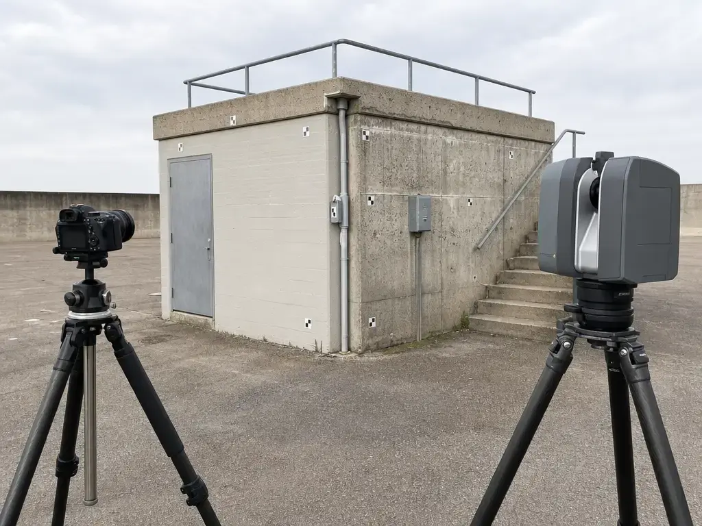
The real comparison is not just passive versus active sensing. It is also about what is measured directly, how quality is reported, and where error enters the project chain. Example TLS datasheets make this explicit. Leica’s RTC360 datasheet lists a 0.5–130 m range, 360°/300° field of view, up to 2,000,000 points per second, and 3D point accuracy of 1.9 mm at 10 m, 2.9 mm at 20 m, and 5.3 mm at 40 m, specified at 68% confidence. [12] FARO’s 2024 Focus family brochure gives model-dependent range at 90% reflectivity of 0.5–400 m, 0.5–200 m, or 0.5–100 m, with up to 2 MPts/s and 3D accuracy of 2 mm at 10 m and 3.5 mm at 25 m. [13] Those are instrument-level examples. They are not the same as registration quality between scans, and they are not the same as final project or network accuracy after control, targets, or scan alignment are applied. ISO 17123-9 exists as a field-procedure reference for evaluating TLS precision, which is another reminder that instrument performance and field procedure are separate layers. [17]
Photogrammetry tends to win when texture is available, access is flexible, and appearance matters along with geometry. TLS tends to win when direct ranging, low-texture surfaces, or rapid capture of large geometry is the main need. Hybrid workflows are often strongest because they combine strong color and texture from photos with direct geometric sampling from laser scans. The useful question is not which sensor is always more accurate, but which workflow is easier to validate for the specific material, geometry, range, and reporting requirement.
| Method | Measures | Strengths | Main cautions |
|---|---|---|---|
| Terrestrial photogrammetry | Inferred 3D from images | Texture/color, flexible viewpoints, lower hardware barrier | Needs texture, geometry, scale/control, and QC |
| TLS | Direct ranges and angles | Dense geometry, explicit device specs | Registration, reflectivity, range limits, occlusions |
| Hybrid | Photos plus TLS/control | Combines appearance detail with stronger geometry | Needs disciplined registration and consistent control |
Control, Check Points, and Scale Bars (How Models Get Real-World Meaning)
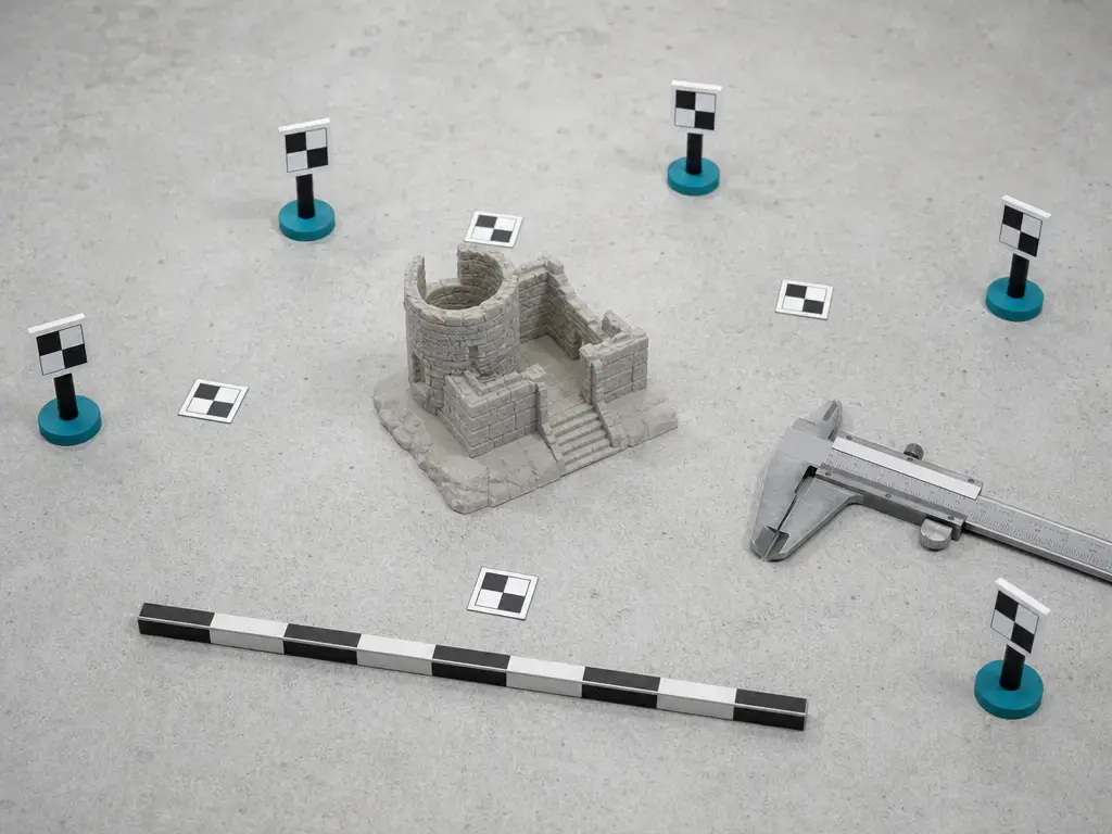
Tie points, control points, check points, and scale bars do different jobs. Tie points are image matches found by the solver. Control points are known object-space references used to constrain the model. Check points are known references held back for validation. Scale bars are known distances used to set or verify size when full georeferencing is unnecessary. In classical workflow descriptions, control points or scaling lengths create the global object coordinate system. [2] Metashape also separates these roles in reporting by distinguishing control and check points and by listing scale-bar distances separately. [3]
Heuristic GCP advice can be useful for planning, but it is not a survey standard. OpenDroneMap’s documentation suggests a minimum of 5 GCPs for most jobs, 8–10 for larger jobs, visibility in at least 5 images per GCP, and placement about 10–30 m from the project perimeter. [10] Those are practical rules of thumb, not proof that a given project is accurate. Distribution, measurement quality, independence of check points, and a documented reference frame still matter more than hitting a target count.
- If you need measurement-grade output, you probably need…
- known control points or scale bars. [2]
- independent check points reserved for validation. [3]
- a documented coordinate system or reference frame.
- reported residuals and checkpoint results that are separate from the fit. [3]
- a validation plan decided before capture, not after the mesh looks good.
Overlap, Viewpoint Diversity, and Network Geometry (Rules of Thumb, Not Laws)
Overlap percentages are best treated as starting points, not guarantees. Pix4D’s general guidance gives at least 75% frontal overlap and 60% side overlap for many cases, 90% for interiors, and for large vertical objects 90% overlap at the same height plus 60% at different heights. [9] These figures are useful planning heuristics, but they remain software guidance. They do not override the actual geometry of façades, interiors, occlusions, or low-texture surfaces.
A second example from Reclamation uses 60% forward overlap and 30% side overlap in a contextual workflow. [4] That does not contradict the higher values above; it shows that overlap advice depends on scene type, scale, and capture method. More overlap can help, but it cannot rescue a weak baseline, repeated texture, poor depth variation, or blocked sight lines. What matters is not just how many photos exist, but whether the viewpoint network adds useful geometric information.
Applications (What It’s Good For — and Where It’s a Risk)
Terrestrial photogrammetry is useful wherever geometry, appearance, and access flexibility matter together. It is well suited to heritage capture, façade documentation, geology and outcrops, accident scenes, construction progress, and appearance-rich digital twins. It is also useful for inspection and as-built context when the surface has enough texture and the operator can see the subject from multiple sides. In those cases, the method preserves visual detail that geometry-only workflows do not capture as naturally. [2]
The conservative boundary is metrology. Photogrammetry can document large textured objects well, but precision part inspection usually needs more controlled setups or metrology-grade optical systems. ISO 10360-13 is a useful boundary reference because it covers acceptance and reverification tests for optical 3D coordinate measuring systems, which is a more demanding context than general 3D documentation. [18]
- Heritage capture — sculptures, monuments, artifacts, and fragile sites.
- Facades/buildings — exterior walls, roofs, architectural detail, and condition context.
- Forensics/accident scenes — scene preservation before evidence or layout changes.
- Geology/outcrops — rock faces, discontinuities, and inaccessible slopes from ground viewpoints.
- Construction progress/as-built visual context — time-based documentation and coordination support.
- Civil infrastructure inspection — bridges, retaining structures, tunnels, and similar assets where texture and access are adequate.
- Reverse-engineering documentation for large textured objects — useful for reference geometry, but not a blanket replacement for metrology.
- Visual digital twins — appearance-rich 3D context for review, communication, and planning.
Standards & Reporting (Keep Brief; Practical Takeaways)
For serious measurement work, standards matter mainly because they force clearer reporting. Instead of vague claims about a model being “highly accurate,” a defensible report should define the reference frame, the control and check strategy, the quality metrics used, and the limits of the deliverable. Relevant boundary references include ISO 19130-1:2018 for imagery sensor models, ISO 19157-1:2023 for data-quality framing, ISO/TS 19159-1:2014 for calibration and validation context, ISO 17123-9:2018 for TLS field procedures, and ISO 10360-13:2021 for optical 3D CMS acceptance testing. [14] [15] [16] [17] [18]
When to Use Terrestrial Photogrammetry, TLS, or Hybrid
If you want the shortest decision rule, terrestrial photogrammetry explained in practical terms means choosing it when the surface has usable texture, you can build a strong camera network, and color or visual context matters along with shape. Its confidence comes from geometry, control, and validation more than from photo count alone. [3] [4] TLS is usually the better fit when direct ranging, predictable device behavior under stated conditions, or low-texture geometry is the priority. [12] [13]
- Choose terrestrial photogrammetry when: the subject is textured, access allows multiple viewpoints, visual appearance matters, and you can place or measure references when needed.
- Choose TLS when: low texture, direct geometric capture, or repeatable instrument specifications are more important than full-color appearance. [12] [13]
- Choose hybrid when: you want both strong geometry and appearance-rich documentation, or when one method covers the other’s blind spots.
FAQ
What is terrestrial photogrammetry?
Terrestrial photogrammetry is a ground-based image-to-3D method. It uses overlapping photos taken from fixed terrestrial positions, estimates camera poses and scene geometry from image matches, and then produces outputs such as point clouds, meshes, or scaled models. [2] [3]
Close range photogrammetry vs terrestrial photogrammetry — what’s the difference?
They overlap, but they emphasize different things. Terrestrial refers to the ground-based platform or location, while close-range usually refers to imaging distance. A common convention places close-range work under about 300 m, but the boundary is not hard-and-fast. [1] [2]
Terrestrial photogrammetry vs terrestrial laser scanning: which is more accurate?
There is no universal winner. TLS gives direct ranging and explicit instrument specs, while photogrammetry depends more strongly on capture geometry, texture, control, and validation. TLS datasheet values are instrument-level examples, not automatic project accuracy. [3] [12] [13]
How accurate is terrestrial photogrammetry?
No universal figure applies. Accuracy is project-specific and should be checked with independent references. Reprojection error describes image-space fit, not final object-space truth, so a model can align cleanly and still have scale or geometric bias. [3]
Do I need ground control points (GCPs), check points, or scale bars?
If measurement matters, usually yes. Control points or scale bars help set size and reference, while check points validate the result independently. OpenDroneMap’s counts and placement advice are useful heuristics, but they are not survey standards. [2] [3] [10]
In terrestrial photogrammetry explained for advanced users, why can low reprojection error still produce a warped model?
Because reprojection error only measures image-space fit. Weak geometry, correlated intrinsics and extrinsics, clustered control, or overfitting to the reference network can still yield a warped object-space solution. Metashape also notes that displayed check-point estimates come from reprojection minimization only. [3] [4]
What camera/lens changes break self-calibration assumptions?
Focus, aperture, or zoom changes can shift the effective camera model during capture. Reclamation also warns that rolling shutter and video compression can distort imagery and usually reduce model accuracy. The safest rule is consistent settings, fixed zoom, and autofocus off. [4]
Sources
- BLM/DOI — Aerial and Close-Range Photogrammetric Technology
- Luhmann et al. — Close-Range Photogrammetry and 3D Imaging (2nd ed.)
- Agisoft — Metashape Pro 2.3 User Manual
- U.S. Bureau of Reclamation — SfM Photogrammetry whitepaper
- USGS — Topographic Mapping
- USGS — Development of photogrammetry in the U.S. Geological Survey
- USGS Thesaurus — structure from motion
- Schönberger & Frahm — Structure-from-Motion Revisited
- Pix4D — Best practices for image acquisition and photogrammetry
- OpenDroneMap — Ground Control Points docs
- ASPRS — 2024 positional accuracy standards announcement
- Leica Geosystems — RTC360 datasheet
- FARO — Focus Premium brochure
- ISO — ISO 19130-1:2018 catalog page
- ISO — ISO 19157-1:2023 catalog page
- ISO — ISO/TS 19159-1:2014 catalog page
- ISO — ISO 17123-9:2018 catalog page
- ISO — ISO 10360-13:2021 catalog page