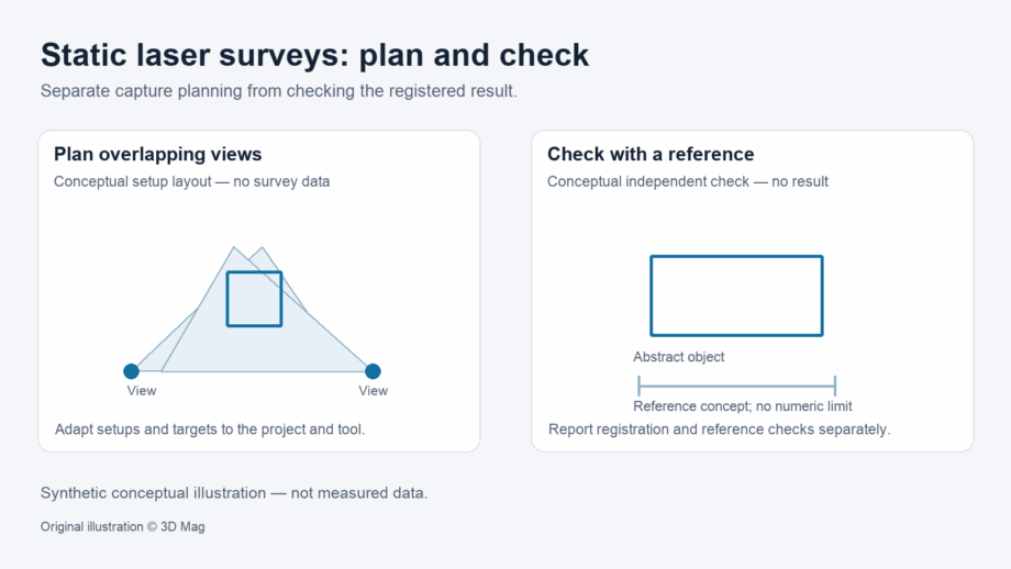
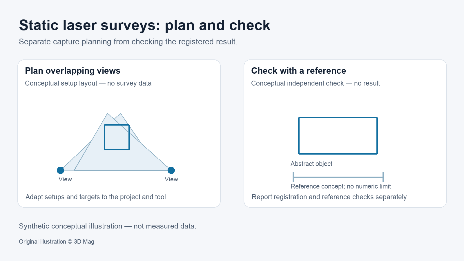

A reliable static terrestrial laser survey needs two things. First, plan for registration before you set up. Second, check the registered result against something independent before you hand it over. Setup placement, target arrangement and scan overlap determine whether the scans register cleanly. Editorial guidance: a registration result mainly shows that the scans agree with each other; whether they agree with the real object needs a separate check. Proving that needs a separate check, such as a known length or an independently measured reference.
The practical guidance below comes mainly from FARO’s knowledge base for its Focus scanners. Any counts, settings and limits are FARO Focus guidance, not universal standards. Other scanners and project specifications may set different requirements. 3D Mag did not perform any of the procedures described here.
Plan static setups before you arrive
FARO’s Focus best-practice guide says a quick sketch of the scanning site can help save time and determine the optimal scanning locations.
When choosing setup positions, the same FARO guidance says to place the scanner in positions where each scan will overlap with another scan, and to scan transition areas like doorways to aid registration. FARO gives no overlap percentage; if your project specification sets one, follow it.
Targets and overlap that make registration workable
According to FARO’s Focus guidance, at least three targets are required for registration, or two if sensor data such as the inclinometer is used. This is a Focus-specific minimum; check your own scanner’s documentation.
Arrangement matters as much as number. FARO advises that each target should be visible from more than one scanner position, and that targets must not be moved during the scanning process.
FARO also recommends arranging targets in unique patterns in three dimensions by varying the height and spacing of the targets.
Resolution, distance and occlusion
FARO defines scan resolution as the number of data points collected and the distance between them, and advises choosing it based on the level of detail needed, the distance to the object of interest and the distance to the targets. Resolution is not accuracy: a dense point cloud can still be wrong, so accuracy is checked separately (see below).
FARO’s guidance notes that obstructions such as trees or columns often require adjusting scanning positions, and that with multiple scans the scan areas should overlap beyond the obstruction.
Glass, mirrors, water and other problem surfaces
The table summarises limits documented in FARO’s Focus guidance. The last column is editorial planning guidance.
| Surface | What FARO’s Focus guidance says | Planning response (guidance) |
|---|---|---|
| Glass | Measuring through glass surfaces will not produce repeatable or accurate results. | Set up on the same side of the glass as the subject. |
| Mirrors and highly reflective surfaces | They can make scanning challenging; covering them with brown paper or tape can minimise their impact. | Cover only where the site owner permits it; otherwise record the affected areas. |
| Water | Water refracts light too much to return a reliable scan result and should be avoided. | Log water surfaces and do not treat points on them as measurements. |
FARO attributes the glass problem to back reflections and refraction. Recording problem surfaces in the field log tells whoever checks the data where gaps or noise are expected.
Checking the registered cloud: three different checks
A good registration report is not proof of accuracy. The FARO documentation describes three distinct checks that answer different questions; report each separately.
Known-length check. FARO suggests placing an item with a known length such as a FARO Scale Bar or meter/yard stick in the first scan area as a way to verify the accuracy of scans after registration is complete.
Comparison with an independent reference system. In its Focus accuracy-check article, FARO describes setting up a network of target spheres and measuring the sphere centre points with a FARO laser tracker, giving them accurate and known locations relative to each other. The Focus scans are then compared with that known reference system. These locations are relative; the article does not describe a georeferenced coordinate system.
For these comprehensive checks, the same FARO article advises placing target spheres or checkerboards completely around the scanner, including at the full horizontal and vertical scan-range points, and at different heights, including high and low.
Two-orientation consistency check. This method needs no external reference. In FARO’s procedure you scan a target network, move the scanner at least 2 m and rotate it, scan again, and register the two sets with target-based registration. FARO states that the point distance should not exceed 2 mm for Focus S70/S150/S350/Max/Premium/Core, 4 mm for Focus 3D/X/XHDR and 6 mm for Focus M70. In this guide, we treat these as model-specific check limits for this procedure, rather than as a general accuracy specification, and the article states no confidence level or environmental conditions for them.
Control, georeferencing and deliverables
Decide what the deliverable is for before deciding how to capture it. In heritage work, Historic England describes laser scanning and photogrammetry as providing visual and metrically accurate base data for heritage applications including conservation planning and condition surveys. Its page, updated 5 January 2022, gives method context and does not set device tolerances.
The sources used here document comparison with a relative reference system, not a georeferencing procedure, coordinate reference system or survey-control tolerances. Take those from the client or project specification, and record how control was established and checked.
A practical validation workflow (guidance, not a reported test)
This is a suggested workflow to adapt to your project. 3D Mag performed no tests or measurements.
- Fix the requirement first: purpose, required tolerance and coordinate system, taken from the project specification.
- Sketch the site and plan setups so each scan overlaps another, including doorways and areas beyond obstructions.
- Place targets in a fixed 3D pattern, each visible from several setups, meeting your scanner manufacturer’s minimum.
- Set resolution by detail and distance, and record the settings used.
- Log glass, mirrors and water, and plan setups or permitted coverings accordingly.
- After registration, run and report the checks separately: known length, independent reference or control comparison where required, and any manufacturer consistency check with its exact model limit and conditions.
- Record how control and georeferencing were established and checked.
Reader questions
How many targets do I need? FARO’s Focus guidance says at least three, or two with sensor data such as the inclinometer, each visible from more than one setup. Other scanners may differ.
Is scan resolution the same as accuracy? No. Resolution describes point count and spacing; accuracy must be checked against a known length or an independent reference.
Can I scan through windows? FARO’s Focus guidance says measuring through glass will not produce repeatable or accurate results. Set up on the near side.
Does a clean registration prove the survey is accurate? Not on its own. The required tolerance comes from the project specification, and the checks above answer different questions.
How do I georeference a TLS survey? The sources used here do not cover it. Follow the project’s survey-control specification.
Sources
This explainer is based on cited published sources; 3D Mag did not conduct hands-on testing. Publisher sponsorship.