
The short answer: what to decide before you shoot
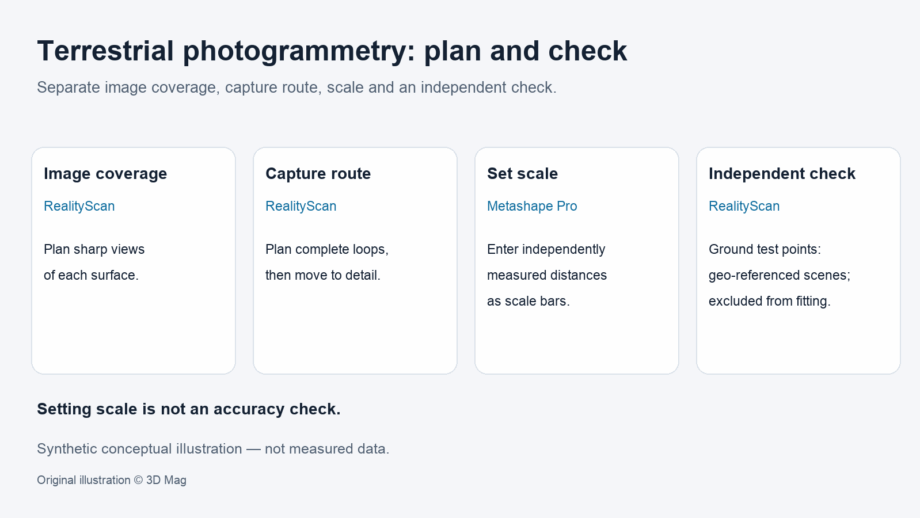
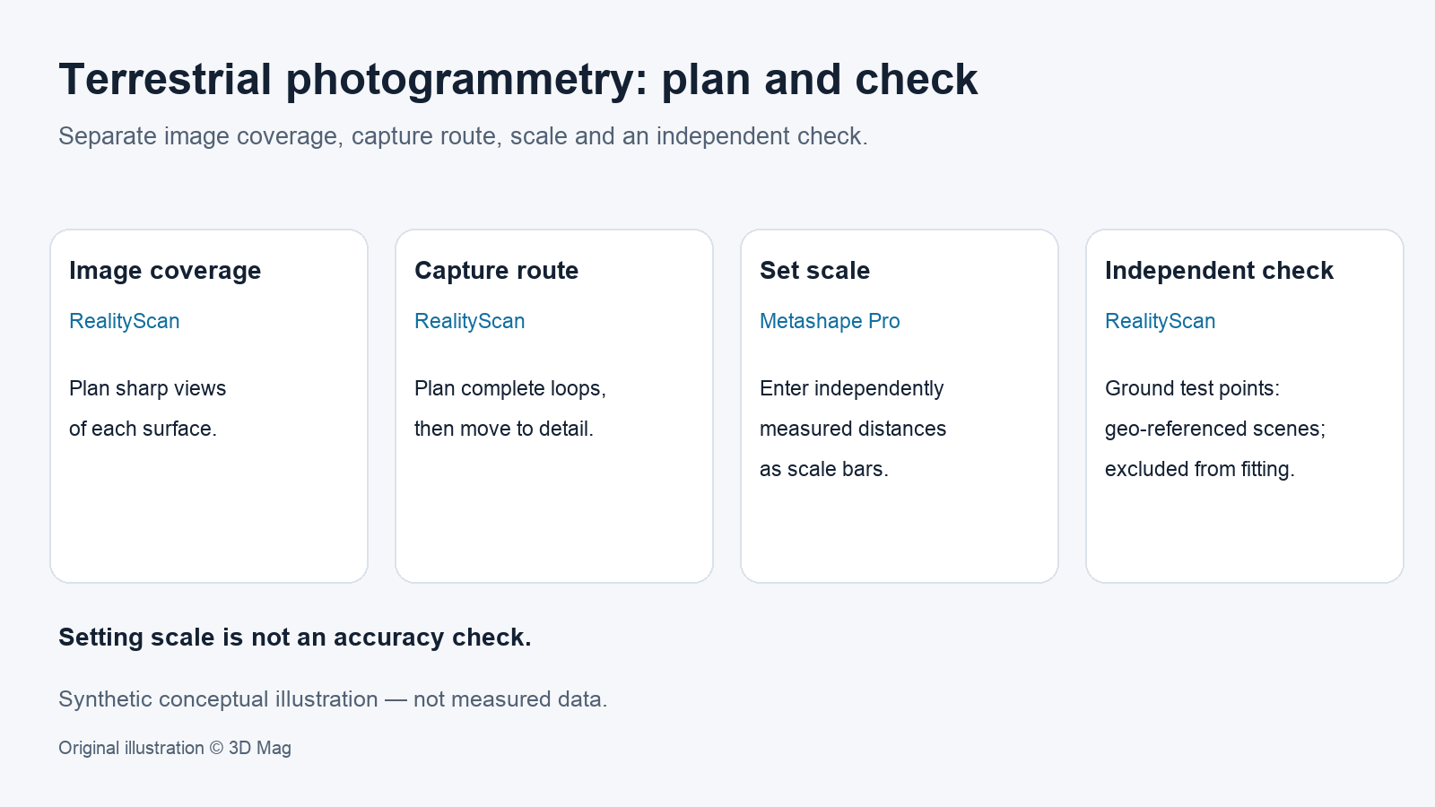
The following is an editorial summary of the sourced sections below. A ground-based (terrestrial or close-range) photogrammetry plan needs four decisions before the first photo. First, image coverage: how many sharp views each surface point gets. Second, the route you walk. Third, how the model will get its scale. Fourth, which independently known points you will hold back to check the result. These are separate jobs. Good coverage does not set scale. A scale reference is not an accuracy check. Small errors on the points used to fit the model do not prove that the model is dimensionally correct.
This article covers planning and checking a capture from the ground, not aerial capture. For a definition of photogrammetry itself, see our explainer What is photogrammetry?.
The guidance below comes from published help pages for Epic Games’ RealityScan and Agisoft Metashape. Each vendor’s advice describes its own software. Where they cover similar ground, they are kept apart rather than merged into one rule.
Camera geometry and overlap: views per point and angle between views
The baseline coverage rule is simple. RealityScan’s photography guide advises that each point in the scene surface be clearly visible in at least two high-quality images, and adds that more is better.
The same RealityScan guide gives an angular limit: do not change the viewpoint by more than 30 degrees between photos. It gives no object size or shooting distance for this figure, so treat it as a general rule of thumb for RealityScan rather than a value tuned to your object.
The selected sources give no numeric forward or side overlap percentage for ground capture. If your organisation uses an overlap target, record where it comes from and do not attribute it to these vendors.
Planning the capture route: loops and coarse-to-fine
For objects you can walk around, RealityScan’s guide recommends complete loops. For statues, buildings and similar subjects, it advises moving all the way around and finishing where you started.
The guide also describes a coarse-to-fine rule. Photograph the whole object first, move around it, and then focus on details. It warns against jumping too close at once and says the approach should be gradual.
As a planning suggestion, sketch the route on a plan before the visit. Mark the loop positions, the points where you will move closer for detail, and any areas that are hard to reach from the ground, since those are where coverage is most likely to fall short.
Light and material limitations: what the selected sources do not settle
Lighting and surface material matter to any photo-based method, but the sources selected for this article do not document how they affect reconstruction. This article therefore makes no sourced claim about reflective, transparent, dark or textureless surfaces, or about lighting conditions.
A practical response is to record these factors for later review. This pre-capture checklist is editorial guidance only and reports no findings:
- Which surfaces are shiny, transparent, very dark or uniform in colour?
- Will the light change during the session, for example through sun movement or cloud?
- Are there hard shadows or areas that cannot be lit from the ground?
- What will you do if a surface does not reconstruct, and who decides?
Check the guidance for your chosen software, or ask a photogrammetry specialist, before relying on any answer.
Setting scale: coded targets and measured scale bars
Agisoft’s coded-target guide describes printed coded targets that are placed in the scene before photography and can then be used in Metashape as reference points for coordinate-system and scale definition.
The same Agisoft page states an edition restriction: markers and scale bars are available only in Metashape Pro. The page shows a modified date of 7 July 2026 and was accessed on 7 October 2026. It gives no version number and does not cover pricing, so check the current licence terms before you plan around this feature.
Target size is set in image space, not on paper. Agisoft recommends that the central circle of a coded target appear with a radius no greater than 30 pixels in the photos and a minimum of about 4-5 pixels, and asks for flat, undeformed targets. The page gives no physical target size in millimetres.
As an editorial suggestion, because the page specifies size only in image pixels, check a test print in a sample photo taken from your planned position before the main session.
Scale comes from measurements you make yourself. Agisoft explains that if linear distances between coded targets have been measured before or after the shoot, they can be entered as scale bars to set the model’s scale. This step sets scale. It is not an accuracy check. To find out whether the scaled model is correct, you need separate points that were not used to build it.
Control points versus test points in reconstruction
RealityScan’s control-point documentation describes three kinds of point. Tie points link images to the same physical location. Ground control points add real-world coordinates. Ground test points, which RealityScan describes for validating geo-referenced scenes, are ground control points excluded from scene optimisation and used to report deviations from defined positions.
RealityScan recommends defining at least 2 control points in 2-5 images, and distributing test points evenly in the scene.
Manual placement has limits. RealityScan’s documentation states that it is difficult for a person to place a point more precisely than 3-4 pixels, whereas natural features are placed with sub-pixel accuracy. The statement appears in its discussion of control-point weight, where it recommends leaving the default weight. The figure is in image pixels and does not translate directly into millimetres.
| Point type (RealityScan terms) | What it does | Counts toward checking? |
|---|---|---|
| Tie point | Links the same physical location across images | No |
| Ground control point | Supplies known coordinates used in optimisation | No, because it shapes the fit |
| Ground test point (geo-referenced scenes) | Known position excluded from optimisation; reports deviation | Yes |
The selected sources do not document an equivalent held-out check-point feature in Metashape, or RealityScan test-point use for scale-only projects that are not geo-referenced. Confirm this in your own software’s documentation.
Validating the model before it becomes a deliverable
Low error on control points can be misleading. RealityScan’s documentation warns that sometimes, especially when a ground control point is defined in only 2-3 images, the system may shift those images to make errors look smaller, while the scene itself is not corrected and a typical “banana effect” remains. Test points can detect this because their error grows.
The following workflow is proposed editorial guidance. 3D Mag performed no capture, reconstruction or export test. Each step names the software whose documentation it reflects:
- Write down the deliverable and the dimensional tolerance before capture. The sources do not supply tolerances.
- Plan a route that shows every surface point in at least two sharp images, uses complete loops, and keeps viewpoint changes within the 30-degree guidance in RealityScan’s photography guide.
- If you use Metashape Pro, place flat coded targets clearly visible in at least a couple of images, sized for the 4-5 px to 30 px central-circle radius that Agisoft recommends.
- Measure several target-to-target distances independently to use as scale bars (Metashape Pro).
- Survey the control points. For geo-referenced RealityScan projects, reserve evenly distributed points as ground test points that stay out of optimisation.
- After reconstruction, review test-point deviations, not just control-point residuals, and investigate the alignment if test-point error grows.
- Record the software, version, settings, coordinate system and check results alongside the deliverable.
The selected sources do not document deliverable formats such as meshes, point clouds, orthoimages or CAD, nor any export behaviour. Confirm these in your software’s own documentation.
Resolution claims versus measurement accuracy
RealityScan’s photography guide states that its users can get very accurate 3D models, “even sub-millimeter resolution”. This is a vendor claim about resolution. The page gives no camera, distance, object or verification method, so it is not a measured accuracy specification.
The same guide says that model resolution depends on image quality, image resolution and distance from the object. It offers a distance calculator, but asks users to treat it with caution and to contact a photogrammetry professional whenever guaranteed precision is required.
Resolution describes how fine the captured detail is. Accuracy describes how close measured positions are to true ones. Only a check against independent references, such as held-out test points, tells you about accuracy for your job.
Reader questions
How many photos should see each point? RealityScan’s guide says each point should be clearly visible in at least two high-quality images, and that more is better.
Is a scale bar the same as an accuracy check? No. In Metashape, measured distances set the model’s scale. In RealityScan, ground test points kept out of optimisation report deviations from known positions in geo-referenced scenes.
Does sub-millimetre resolution mean sub-millimetre accuracy? No. RealityScan ties resolution to image quality, resolution and distance, and advises consulting a professional when guaranteed precision is needed.
Can terrestrial photogrammetry replace terrestrial laser scanning? The sources selected here do not compare the two, so this article draws no conclusion.
Sources
This explainer is based on cited published sources; 3D Mag did not conduct hands-on testing. Publisher sponsorship.