
If you must accept or reject parts against toleranced features, the deciding question is not which machine is better. It is whether the measurement can show that each feature is within tolerance, with a stated uncertainty. On a coordinate measuring machine (CMM), one central choice is between collecting discrete touch-trigger points and running a tactile scanning probe along the surface. The right choice depends on several things: whether size and position or form dominates the feature, how the part is sampled, fixtured and held at temperature, and whether the result is traceable and fit for the decision. This explainer does not rank CMMs against optical 3D scanners, because the sources used here do not support such a ranking.
The inspection question comes first
Start with the feature, its tolerance and its function. Then decide what measurement evidence would support an acceptance decision. A 1993 report from NIST describes the historical gauge maker’s rule as a ratio of part tolerance to measurement uncertainty, which by then was often applied as 4:1. The same report questions whether such a ratio settles the decision on its own, as covered below.
Tactile CMM probing: discrete points and continuous scanning
In this article, “scanning” means tactile scanning probes on a CMM. It does not mean optical or structured-light 3D scanners.
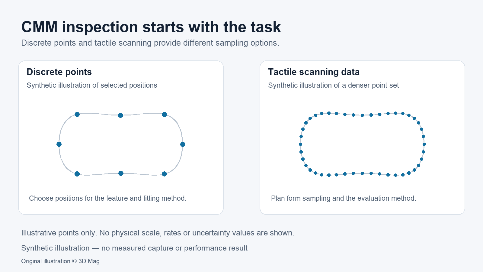
Probe manufacturer Renishaw describes touch-trigger probes as gathering discrete points on the surface, while scanning systems acquire large quantities of surface data. Renishaw also states that scanning probes can acquire discrete points in a similar way to touch-trigger probes.
According to Renishaw, scanning probes can acquire several hundred surface points each second, enabling measurement of form as well as size and position. That is a general manufacturer description, not a specification for a particular probe, machine or scanning speed.
The operating principle has its own constraint. During contact scanning, the stylus is moved along the surface. Renishaw notes that the stylus deflection must be kept within the probe’s measurement range throughout the measurement.
When form data matters
Renishaw calls scanning ideal where the form of a feature is a significant element of the overall error budget. That is a manufacturer’s recommendation, not independent guidance, but it points to a real planning question: is the feature’s form part of what you are accepting?
For the nominally circular feature discussed by NIST, the fitting method can change the answer even when many points are taken. The 1993 NIST report states that for a nominally circular feature, different diameter-fitting methods may produce significantly different results depending on the part’s form error, even with a perfect CMM. Choose the method that reflects how the part functions.
Sampling strategy and feature access
In 1993, NIST reported that most CMM measurements used relatively few points, typically fewer than ten per part feature. That observation is dated and should not be read as a description of current practice.
The underlying point still applies to planning. In a thought experiment with a perfect CMM, environment and algorithm, the NIST report shows that remeasuring a part with form error using a different sampling strategy produces a different computed result.
Reaching a feature can add uncertainty of its own. When a single measurement uses multiple styli or probe positions, NIST states that the resulting errors must be assessed and accounted for when evaluating CMM measurement uncertainty.
Fixtures and temperature
The 1993 NIST error-source table lists distortion due to clamping and slippage under probing force among the part-fixturing sources of uncertainty. The fixture therefore belongs in the measurement plan, not only in the setup.
On temperature, the same 1993 NIST report observed that most CMMs were specified to operate over a narrow range of thermal conditions but were often used well outside those limits. Check your own machine’s documented conditions against the environment where it is actually used.
Traceability, uncertainty and acceptance
The international vocabulary of metrology (VIM, entry 2.41) defines metrological traceability as a property of a measurement result whereby the result can be related to a reference through a documented unbroken chain of calibrations, each contributing to the measurement uncertainty.
Traceability does not settle the question by itself. A note to the same VIM entry states that traceability does not ensure that the measurement uncertainty is adequate for a given purpose.
Gauge ratios have similar limits. The 1993 NIST report states that satisfying a gauging ratio such as 4:1 usually does not determine the confidence of the measurement. It also notes that when a measurement result is close to the tolerance limits, a part accepted on one measurement may be rejected on re-measurement. Set an explicit decision rule for results near the limits, and do not treat any ratio as a universal acceptance rule.
| Planning factor | What to decide | Documented basis |
|---|---|---|
| Data type | Discrete points, or tactile scanning where form is a significant part of the error budget (Renishaw view) | Renishaw manufacturer description |
| Fitting method | A diameter-fitting method that reflects the part’s function | NIST, 1993 |
| Sampling and access | Number and location of points, plus the uncertainty added by multiple styli or probe positions | NIST, 1993 |
| Fixture and temperature | Clamping distortion, slippage and the thermal operating conditions | NIST, 1993 |
| Acceptance | A traceable result whose uncertainty is adequate for the decision | VIM 2.41 |
Combining workflows: a proposed planning method
The steps below are editorial guidance. They are not a performed test and do not report any measured results.
- List each toleranced feature, its tolerance and its functional meaning.
- Decide, feature by feature, whether size and position or form dominates.
- Choose a fitting method that matches the part’s function.
- Define the sampling plan and confirm that the styli or probe orientations can reach every feature.
- Plan fixturing and temperature control.
- Write a task-specific uncertainty statement supported by a documented traceability chain.
- Set the decision rule for results near the tolerance limits.
- If you are considering a second method for some features, validate it on those same features, with its own documented uncertainty, before using it for acceptance.
Reader questions
Is a 3D scanner more accurate than a CMM? The sources used here do not answer that question. Any answer depends on the specific task, the feature and the documented uncertainty of each method. No ranking is made here.
Does a traceable calibration mean my measurement is good enough? No. A note in VIM 2.41 states that traceability does not ensure that the measurement uncertainty is adequate for a given purpose.
What this evidence does not settle
The sources used here do not cover how optical scanners work, or their uncertainty or traceability. They include no current acceptance-test standards and support no certification claim. The NIST observations date from 1993, and current practice may differ.
Sources
This explainer is based on cited published sources; 3D Mag did not conduct hands-on testing. Publisher sponsorship.