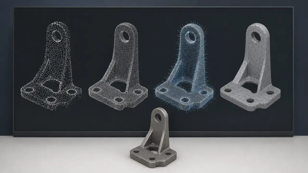

Summary
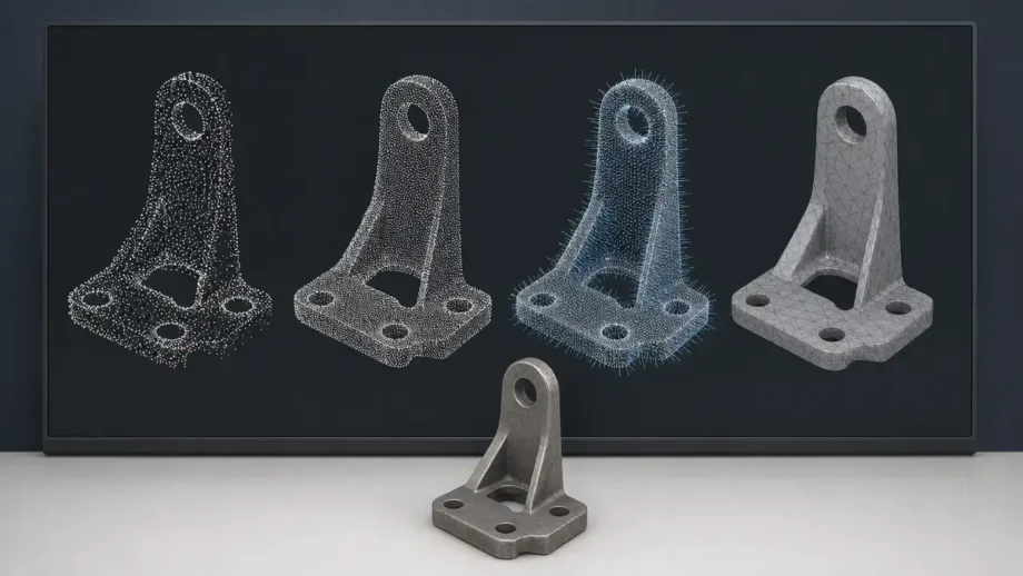
To convert point cloud to 3D model data into something usable, start by choosing the deliverable. You may keep the point cloud as measurement evidence, reconstruct a triangle mesh for visualization or printing, rebuild a CAD or surface model for editability, or create a BIM/as-built model for semantic context. E57 stores 3D point data, point attributes, and 2D imagery, while LAS 1.4 is a point-cloud exchange format for lidar-style point records and attributes. [3] [4]
Pick the deliverable first
The same scan can support very different outputs, so decide early whether the job is really point cloud to mesh, point cloud to CAD model, or a semantic as-built workflow. Open3D documents three common reconstruction methods for mesh creation, Fusion can convert qualifying mesh bodies into solid or surface bodies, and Creaform’s Scan-to-CAD tooling focuses on NURBS and extracted entities rather than raw triangles alone. [5] [16] [18]
| Deliverable | Best for | Typical formats | Main risk |
|---|---|---|---|
| Point cloud | Measurement record, traceability, reprocessing | E57, LAS, XYZ | Limited editability |
| Triangle mesh | Visualization, simulation, printing prep | STL, OBJ, DAE | Holes, noise, and poor topology |
| CAD/B-rep or surface model | Editing, parametric reuse, manufacturing intent | STEP, IGES, surface bodies | Reconstruction may miss design intent |
| BIM/as-built semantic model | AEC documentation, asset context, facility workflows | BIM-oriented deliverables | Geometry alone is not enough |
When not to convert yet
Do not convert immediately if the scan is still incomplete, misaligned, or still needed as source evidence. In those cases, keep the point cloud and finish registration and quality checks first, because later reconstruction can hide what was actually captured. [12] [13] [4]
Terminology and historical background
Registration and reconstruction are related, but they are not the same step. The classic ICP paper appeared in 1992 in IEEE TPAMI 14 and addresses six degrees of freedom registration, which is why ICP remains the reference name when scans must be aligned before conversion. Later, Poisson surface reconstruction, published in 2006 on pages 61–70, formalized a different idea: reconstructing a surface from oriented points, with the authors describing the method as resilient to data noise. Modern preprocessing sits between those stages, with tools such as VoxelGrid reducing density by replacing the points inside each voxel with their centroid. [12] [6] [11]
What a point cloud contains
A point cloud is a set of measured XYZ coordinates, often with additional fields such as color, intensity, classification, normals, or scanner-specific metadata. Some workflows preserve normals from the sensor or earlier processing, while others estimate them later or omit them entirely. E57 can store 3D point data, point attributes, and 2D imagery, while LAS 1.4 carries lidar-style point records and attributes. [3] [4]
Those fields matter because point cloud data to 3D model conversion can discard useful information if export preserves only coordinates. Statistical outlier removal evaluates neighborhood distances against a mean-plus-standard-deviation threshold model, and VoxelGrid simplifies dense scans by approximating the points in each voxel with their centroid. Both are useful, but both can also remove information if used too aggressively. E57, LAS, or XYZ carry points; STL, OBJ, and STEP carry geometry in very different ways. [10] [11]
Point cloud, mesh, CAD, and BIM/as-built are different deliverables
A point cloud is a measured sample set. A triangle mesh is a connected surface approximation inferred from those samples. In a point cloud to mesh workflow, topology, watertightness, and triangle quality are created during reconstruction rather than captured directly by the scanner. Fusion can convert a mesh body to a solid or surface body, and a watertight mesh can convert to a solid body, but that does not make every mesh suitable for downstream engineering use. [16]
A surface or NURBS model is closer to editable geometry because curves and patches are fit to interpreted scan features. That is the logic behind scan-to-CAD workflows: Creaform documents NURBS surface generation plus geometric entity extraction, including 2D/3D entities, curves, and cross-sections. Parametric CAD/B-rep goes further by encoding design intent, so the result can be edited as features instead of only moved, shaded, or remeshed. Some software can import both mesh-like and CAD-like formats — Artec Studio 20 lists STL, OBJ, STEP, STP, IGES, IGS, X_T, and SAT support — but import support is not the same as native editability. [18] [17]
An as-built model is usually semantic as well as geometric, especially in AEC. It may carry walls, openings, systems, and asset labels in addition to shape, so it is not just a prettier mesh. That is why “3D model” is only umbrella language: the right deliverable may be a mesh for visualization, a CAD model for redesign, or an as-built model for documentation. CGAL’s mesh-processing documentation keeps border handling, closure, and repair as mesh topics, which is separate from point-cloud exchange itself. Materialise’s 7-minute tutorial recorded in 3-matic 14 is best treated as one bounded workflow example, not as a universal definition of the output. [20] [19]
| Output | Best for | Typical formats | Main risk |
|---|---|---|---|
| Point cloud | Source evidence, measurement, reprocessing | E57, LAS, XYZ | Not directly editable as shape |
| Triangle mesh | Visualization, simulation, printing prep | STL, OBJ, DAE, FBX | Holes, bad topology, and limited semantics |
| Surface/NURBS model | Smooth reconstructed geometry | IGES, STEP, surface bodies | Patch fitting can miss sharp design features |
| Parametric CAD/B-rep | Editing, redesign, manufacturing intent | STEP, native CAD | Conversion from scan may be approximate |
| BIM/as-built model | AEC coordination and asset context | BIM-oriented deliverables | Geometry alone is not enough |
STL and OBJ are not editable CAD. If the deliverable must be edited as design geometry, the goal is point cloud to CAD model, not simply exporting a mesh.
Core workflow: from scan data to usable model
To convert point cloud to 3D model data in a controlled way, follow the order of the data rather than the order of the software buttons. First import and confirm units, then crop or segment the useful area so background geometry does not bias later steps. Next register or verify alignment, because point cloud alignment affects everything downstream. After that, remove outliers and noise, downsample only if needed, estimate and orient normals, reconstruct the surface, repair holes and topology, decimate or smooth carefully, validate against the scan or a reference, and export for the intended use. ICP is the classic six-degree-of-freedom registration method from 1992, while CloudCompare exposes diagnostics such as number of iterations, RMS difference, and final overlap for checking fit quality. StatisticalOutlierRemoval and VoxelGrid are common cleanup tools, but they should be treated as controlled preprocessing, not as automatic improvement. [12] [13] [10] [11]
- Import and check units
- Crop/segment the useful area
- Register or verify alignment
- Remove outliers and noise
- Downsample only if needed
- Estimate and orient normals
- Reconstruct the surface
- Repair holes and topology
- Decimate/smooth carefully
- Validate against scan/reference
- Export for the intended use
Meshing can also be heavy on local storage and temporary files. Autodesk ReCap’s local scan-to-mesh guidance recommends temporary free space equal to 5× the point cloud size on the C: drive, which is a practical reminder that conversion is not only a geometry problem. [14]
AEC/survey note on units, CRS, and large coordinates
For AEC and survey data, local coordinates are often easier for modeling, while global coordinates are needed for site context and alignment with other datasets. Large coordinate values can create display or precision problems in some downstream tools even when the scan itself is fine; if a project-specific universal limit is needed, no reliable figure found. When the workflow is used as metrology rather than only geometry processing, ISO 10360-13:2021 provides acceptance and reverification context for optical 3D coordinate measuring systems, and NIST keeps the distinction between accuracy and precision explicit. [1] [2]
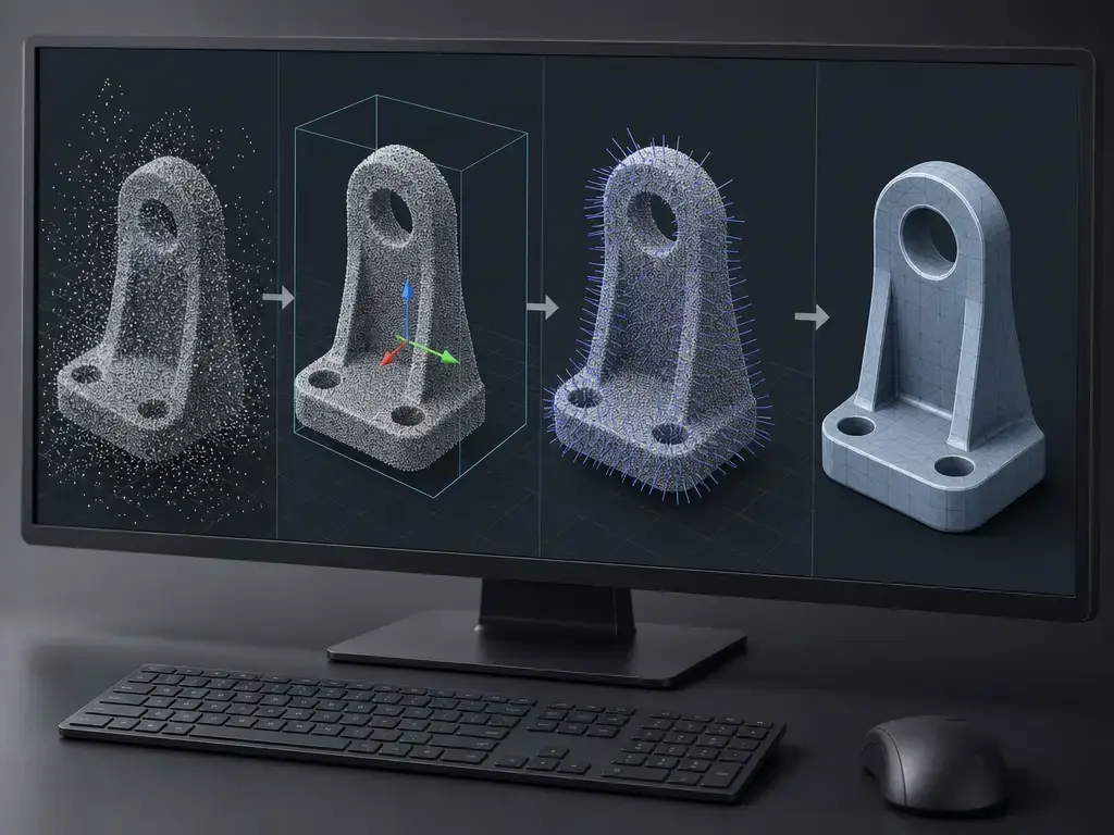
Cleaning and aligning the point cloud before meshing
Cleaning should remove acquisition artifacts, not reshape the object. Start with outlier removal, then inspect overlap regions for duplicate passes, drifting frames, and partial coverage where only one side of a surface was captured. In practice, duplicate overlap can thicken edges or create double walls, while partial coverage can leave gaps that later get mistaken for holes in the object itself. PCL’s StatisticalOutlierRemoval uses a threshold based on mean distance plus a standard-deviation multiplier, with example parameters such as setMeanK(8) and setStddevMulThresh(1.0). [10]
Aggressive cleanup can remove thin edges, slots, embossed text, weld beads, or worn surfaces. VoxelGrid downsampling is also a tradeoff, not an automatic improvement: it approximates each voxel by its centroid, which helps with large scans but can soften narrow features if used too early or too coarsely. After cleanup, registration should be checked with ICP, the classic 1992 six-degree-of-freedom alignment reference. CloudCompare’s diagnostics — number of iterations, RMS difference, and final overlap — help judge whether the fit is stable, but ICP RMS is a fit diagnostic, not proof of absolute accuracy. [11] [12] [13]
Surface reconstruction methods
For point cloud to mesh conversion, the reconstruction method should match the shape and sampling pattern rather than just the software menu. Open3D documents three widely used reconstruction methods: alpha shapes, ball pivoting, and Poisson surface reconstruction. Poisson, published in 2006 on pages 61–70, reconstructs a surface from oriented points and was described by its authors as resilient to data noise, which is why it is often chosen for uneven or imperfect scan data. Screened Poisson, published in ACM TOG 32(3), Article 29, in June 2013, modifies that family of methods so the reconstructed surface can adhere more closely to the input samples. [5] [6] [7]
Ball pivoting and alpha shapes are different tools with different failure modes. Open3D notes that ball pivoting assumes the point cloud has normals, so its results depend heavily on normal quality and orientation. Alpha shapes are often useful when sparse data or boundary behavior matters more than smooth interpolation. In thin, edge-like, or open geometry, alpha-shape or ball-pivoting results may preserve sampled structure better than a smoothing-heavy approach, but they can also leave gaps where sampling is irregular. By contrast, Poisson tends to close and smooth more aggressively, which can help with continuous surfaces and hurt when cavities or open boundaries must stay open. [5] [6]
A 2.5D Delaunay-style triangulation is best understood as a height-field case: each plan-view location maps to one surface height, so the surface can be triangulated as a graph over a base plane rather than as an arbitrary closed shell. That works well for floors, terrain, roofs, or other single-valued surfaces, but it breaks down when the object folds back over itself or contains vertical walls, deep undercuts, or overlapping surfaces.
Software defaults should be treated as examples, not recommendations. PyMeshLab documents screened Poisson defaults such as Interpolation Weight 4 and Gauss-Seidel Relaxations 8, while CloudComPy documents example Poisson defaults such as depth=8, finestCellWidth=0.0, samplesPerNode=1.5, pointWeight=2.0, and threads=1, with depth d interpreted on a 2^d × 2^d × 2^d grid. Those values are software defaults, not universal best practice. [8] [9]
Normals are estimated and oriented, not just present
Normals are a workflow input, not just a label. Poisson uses oriented points, and Open3D’s ball-pivoting implementation assumes normals, so wrongly oriented normals can close cavities, bridge separate surfaces, or erase openings that should remain visible. [6] [5]
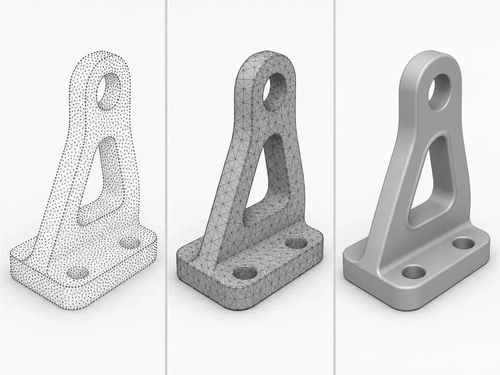
From point cloud to mesh
A good point cloud to mesh result is not just a closed shell. It is a mesh whose triangles follow the scan closely enough for the intended use without inventing too much geometry or carrying an unmanageable triangle count. For visualization, simulation prep, or a printable proxy, automatic meshing is often enough if the surface captures the shape with acceptable deviation. That does not make it final by default, and it does not remove the cost of processing: Autodesk ReCap’s local scan-to-mesh guidance recommends temporary free space equal to about 5× the point cloud size. [14]
- no major holes
- no flipped normals
- no non-manifold edges where solid conversion is needed
- no floating noise islands
- acceptable deviation against scan
- triangle count suitable for downstream software
Mesh repair is where many conversions become usable or fail. CGAL treats border handling, closure, and repair as mesh-processing topics, which is separate from point-cloud exchange itself. Fusion can convert a mesh body to a solid or surface body, and watertight meshes can convert to solid bodies, but watertight does not automatically mean accurate, printable, or CAD-ready. Export also depends on the next tool: Autodesk documents ReCap local mesh outputs including DAE, FBX, GLTF, NWC, RCMR, STL, USD, and OBJ, so the best format is the one your downstream software actually accepts without breaking the workflow. [20] [16] [15]
From point cloud to CAD model
A point cloud to CAD model workflow is not the same as exporting a mesh. Scan to CAD means reconstructing design intent from measured geometry, so the editable result is usually rebuilt from interpreted geometry instead of inherited directly from triangles. Fusion can convert mesh bodies to solid or surface bodies, and watertight meshes can become solids, but that is still a mesh-conversion step rather than a guarantee of clean parametric CAD. [16]
In practice, CAD reconstruction starts by recognizing primitives such as planes, cylinders, cones, and spheres, then fitting sketches, curves, NURBS surfacing, and finally B-rep solids where the geometry warrants it. Creaform’s Scan-to-CAD module explicitly supports NURBS surface generation and geometric entity extraction, including 2D/3D entities, curves, and cross-sections. Feature recognition limits matter here: wear, scan noise, occlusion, and weak edges can all confuse automatic fitting, so many reverse-engineering jobs still require manual judgment. Artec Studio 20’s documented import support across STL, OBJ, STEP, STP, IGES, IGS, X_T, and SAT shows format coverage, not identical editability across those formats. [18] [17]
Editable CAD is often a regularized reconstruction rather than a literal copy of every scanned imperfection. Small dents, wear marks, or waviness may be removed so the CAD reflects nominal design intent instead of the exact as-scanned condition. Materialise’s 7-minute tutorial recorded in 3-matic 14 is a reminder that this is usually a workflow with interpretation steps, not a universal one-button process. [19]
As-scanned vs design-intent example
A worn shaft may scan as slightly oval, but the CAD model is often rebuilt as a true cylinder because the goal is a design-intent part, not a wear record. In that case, the scan preserves condition, while the CAD model regularizes the part back toward nominal geometry for reuse in engineering. [18]
File formats and software categories
Format choice follows deliverable choice. If the goal is source evidence or later reprocessing, use a point-cloud exchange format such as E57 or LAS. E57 stores 3D point data, point attributes, and 2D imagery, while LAS 1.4 is used for lidar-style point records and attributes. If the goal is point cloud to mesh, choose a format that preserves the geometry your next tool needs. If the goal is point cloud to CAD model, the exchange format must support the actual deliverable rather than merely opening in a viewer. [3] [4]
| Format | Keeps points / mesh / CAD topology? | Typical attributes | Typical use |
|---|---|---|---|
| E57 | Points | Color, intensity, imagery, metadata | Scan storage and exchange |
| LAS/LAZ | Points | Lidar-style attributes | Survey and lidar exchange |
| PLY | Points or mesh | Color, normals, custom fields | Research and interchange |
| OBJ | Mesh | Normals, UVs, materials | Visualization and exchange |
| STL | Mesh | Usually none | Printing and simple mesh handoff |
| STEP | CAD topology | B-rep geometry and topology | Editable engineering exchange |
| IGES | CAD/surface geometry | Curves and surfaces | Legacy CAD exchange |
Interoperability is not editability. A file may open in many tools and still be a dead end for design changes, because mesh exchange and CAD topology are different things. Fusion’s Convert Mesh tool can turn a mesh body into a solid or surface body, but that remains a conversion path rather than native feature history. Likewise, Artec Studio 20’s documented support for both mesh-like and CAD-like imports shows boundary coverage, not equal editing behavior. Autodesk’s ReCap output list is useful for the same reason: it shows documented handoff options, not a ranking of formats. [16] [17] [15]
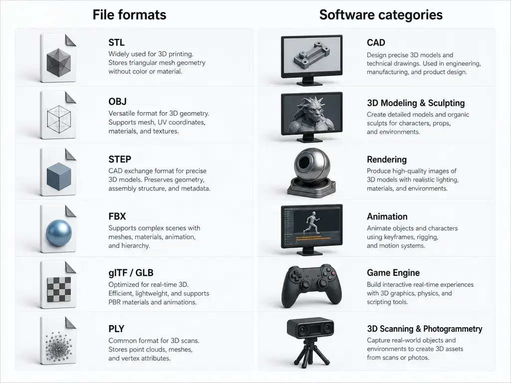
Metrics glossary and validation
Measurement language matters because many workflow mistakes are really terminology mistakes. Accuracy and precision are different concepts in NIST’s metrology usage, and ISO 10360-13:2021 matters only as testing context for optical 3D coordinate measuring systems, not as a universal quality badge for every scan-to-model workflow. Resolution is different again: NIST notes that resolution is about a measurement system’s ability to detect and faithfully indicate small changes, and displayed digits alone do not establish it. [2] [1] [21]
| Metric | What it means | What it does not mean | Example misuse to avoid |
|---|---|---|---|
| Accuracy | How close a result is to a reference or true value | It does not mean repeated results agree tightly | Calling a biased scan “accurate” because it is repeatable |
| Precision | How closely repeated results agree with each other | It does not mean the result is correct | Treating repeatability as proof of truth |
| Resolution | Smallest change the measurement system can meaningfully indicate | It is not just the number of displayed digits | Assuming more decimals mean better measurement |
| RMS residual | Typical size of registration or fit residuals | It does not prove absolute dimensional accuracy | Using ICP RMS alone as a pass/fail criterion |
| Deviation | Difference between compared datasets or surfaces | It does not identify the cause of the difference | Assuming every deviation is noise |
| Tolerance | Allowed variation for the intended use | It does not describe measurement quality by itself | Checking geometry without the tolerance band |
| Uncertainty | Quantified doubt associated with a result | It is not the same as one signed error value | Reporting one number with no context |
| Repeatability | Agreement under the same conditions | It does not guarantee agreement in a different setup | Using one stable setup to justify all future scans |
Validation method should match the deliverable. Cloud-to-cloud checks answer how well point sets align, cloud-to-mesh checks answer how closely the reconstructed surface follows the scan, and mesh-to-CAD comparison shows how much regularization or simplification entered during reverse engineering. Comparison to a traceable reference answers a different question again: whether the whole workflow agrees with an external standard or reference setup. CloudCompare’s ICP tools expose RMS difference, number of iterations, and final overlap, but those are registration diagnostics, not proofs of absolute dimensional accuracy. If a universal accuracy figure is needed for point-cloud-to-model work in general, no reliable universal figure found. [13] [12] [1]
| Validation method | What it answers | Best for | Limit |
|---|---|---|---|
| Cloud-to-cloud | How well two point sets align | Registration checks, overlap review | Depends on overlap and coverage |
| Cloud-to-mesh | How closely the mesh follows the scan | Reconstruction checking | Mesh can hide local errors |
| Mesh-to-CAD | How much the CAD regularizes the scan-derived shape | Reverse-engineering review | Simplification may be intentional |
| Comparison to traceable reference | How far the result is from a known standard | Metrology and acceptance testing | Requires a trustworthy reference setup |
ICP comes from the 1992 six-degree-of-freedom registration paper, so it is a registration method, not an accuracy certificate. A low RMS can still result from poor overlap, repeated geometry, or an overfit region. In practice, use tolerances, uncertainty, repeatability, and external references together instead of relying on one alignment metric. [12] [13]
Applications
Reverse engineering often starts with a mesh and moves to CAD only if editability is required. That makes point cloud to mesh a useful intermediate deliverable for many manufactured parts, because inspection, fit checks, simulation, and printing prep often need usable shape before they need design intent. If the goal is redesign or reuse in engineering, point cloud to CAD model is the better target. Fusion’s mesh conversion features and Creaform’s documented entity extraction and NURBS generation reflect that split between geometry proxy and editable reconstruction. [16] [18]
In fabrication, heritage, and AEC work, the useful output changes again. A 3D-printing pipeline may only need a repaired mesh. Cultural-heritage workflows may retain the original point cloud for documentation while also generating a mesh for visualization. In AEC, the as-built model is often the real deliverable because geometry alone is not enough. Artec Studio 20’s mixed import support and Materialise’s 3-matic tutorial are useful only as boundary examples: they show what specific software can exchange or reconstruct, not that every workflow produces the same kind of model. [17] [19]
Limitations and common failure modes
Capture-driven failures usually begin before reconstruction. Occlusion leaves missing surfaces, glossy or transparent materials can produce sparse or unstable returns, and deep recesses often get undersampled from the start. If the object was not visible to the sensor, later mesh repair cannot recover information that was never measured. The result may look smooth from one angle while still hiding holes, doubled surfaces, or broken edges elsewhere. ReCap’s local scan-to-mesh guidance also shows that the process can be resource-heavy, with temporary storage recommendations around 5× the point cloud size. [14]
Processing-driven failures often come from trying to clean up too much. Statistical outlier removal uses a mean-plus-standard-deviation threshold model, and VoxelGrid simplifies data by replacing points within a voxel with their centroid. Filtering, smoothing, hole filling, and decimation can remove real geometry as well as noise. Thin ribs, sharp steps, embossed text, worn edges, and weld beads are easy to damage this way. Wrongly oriented normals can also mislead reconstruction: Poisson uses oriented points, and ball pivoting assumes normals, so the algorithm may close cavities or bridge separate surfaces in ways that are mathematically consistent but wrong for the part. [10] [11] [6] [5]
Downstream failures appear when the mesh becomes too large, too fragmented, or topologically unsuitable for the next tool. A watertight mesh can convert to a solid in Fusion, but that does not guarantee good downstream CAD behavior. Non-manifold edges, border problems, and closure issues remain mesh-processing concerns in CGAL’s terminology, and those issues often block point cloud to CAD model work from becoming editable geometry. The failure mode to watch for is not only export failure, but also the quieter case where the file opens successfully and no longer matches the measured object closely enough for inspection, redesign, or documentation. [16] [20]
Current research and market context
Automation around scan to CAD and surface reconstruction has improved, but it remains validation-dependent rather than self-certifying. Current toolchains increasingly combine entity extraction, curve generation, NURBS surfacing, and parametric reconstruction, as Creaform’s Scan-to-CAD documentation shows. At the same time, mesh repair is still a separate technical discipline from point-cloud exchange, so better automation does not remove the need to check topology and fit. Materialise’s 7-minute 3-matic tutorial is best treated as a bounded workflow example, not as a benchmark for what every point cloud to mesh or point cloud to CAD model task can achieve. [18] [20] [19]
Final pre-production checklist
Choose the deliverable first, then check whether the result still matches the scan and the intended downstream use. Mesh if visualization or printing is enough, CAD if editability is required, BIM/as-built if semantics matter, and keep the point cloud if source evidence is the deliverable.
- Keep the point cloud if source evidence, later reprocessing, or metrology traceability is the deliverable.
- Choose point cloud to mesh if visualization, printing prep, or a geometric proxy is enough.
- Choose point cloud to CAD model if the geometry must be edited, regularized, or reused in engineering work.
- Choose BIM/as-built if semantic context matters as much as shape.
- Check whether the mesh can be converted to a solid or surface body if your downstream CAD tool requires it. [16]
- Confirm that the software can actually handle the import and export boundary you need, such as mesh and CAD-like imports in Artec Studio 20 or NURBS/entity workflows in Creaform Scan-to-CAD. [17] [18]
- Treat mesh validity and repair as a separate step from point-cloud exchange. [20]
The compact rule is simple: to convert point cloud to 3D model data well, finish only when the chosen output is usable for its specific purpose, not when the software stops processing.
FAQ
How do you convert a point cloud to a 3D model?
Choose the target deliverable first, then move through alignment, cleanup, normals, surface reconstruction, repair, validation, and export. If the target is a mesh, methods such as Poisson or ball pivoting may fit; if the target is CAD, the scan is usually interpreted into curves, NURBS, entities, and solids rather than copied directly as triangles. [5] [6] [18]
What is the difference between point cloud to mesh and point cloud to CAD model?
Point cloud to mesh produces triangle surfaces for viewing, printing, or simulation prep. Point cloud to CAD model aims for editable geometry, so the result is usually rebuilt from primitives, sketches, fitted surfaces, and design-intent interpretation. Creaform’s Scan-to-CAD documentation illustrates that distinction because it emphasizes NURBS and extracted entities instead of only triangle output. [18]
Do I need normals before Poisson or ball-pivoting reconstruction?
Yes. Poisson reconstruction uses oriented points, and Open3D’s ball-pivoting method assumes the point cloud has normals. In practice, that means normals usually need to be estimated and oriented consistently before those methods work well. [6] [5]
Which validation method should I use for cloud-to-mesh vs mesh-to-CAD?
For cloud-to-mesh, use cloud-to-cloud or cloud-to-mesh checks to see how closely the reconstructed surface follows the scan. For mesh-to-CAD, compare the CAD result back to the scan-derived geometry, because regularization may be intentional. CloudCompare’s ICP diagnostics, including RMS difference and final overlap, are useful for fit checking, but they do not by themselves prove dimensional accuracy. [13]
When should I keep the point cloud instead of converting it?
Keep the point cloud when the source data itself is the deliverable, such as for traceability, later reprocessing, survey records, or metrology review. Also keep it if the scan is incomplete or still being registered, because later reconstruction can hide what was actually captured. [4] [12] [13]
How does as-scanned geometry differ from design-intent CAD?
As-scanned geometry shows measured condition, including wear, dents, and manufacturing variation. Design-intent CAD often regularizes that shape back to nominal forms, so a worn shaft may be rebuilt as a true cylinder or an uneven face as a clean plane. That is why scan to CAD is a reconstruction task, not just a format conversion. [18]
Why is ICP RMS not proof of dimensional accuracy?
ICP RMS measures how tightly two datasets align during registration, so it is a fit diagnostic rather than an absolute accuracy guarantee. CloudCompare exposes RMS difference, iteration control, and final overlap, but a low RMS can still come from repeated geometry, poor overlap, or local overfitting. [12] [13]
Sources
- 1. ISO 10360-13:2021 optical 3D coordinate measuring systems — acceptance and reverification tests
- 2. NIST/SEMATECH e-Handbook glossary
- 3. Library of Congress format description for ASTM E57 3D imaging data file
- 4. ASPRS LAS 1.4 R15 specification
- 5. Open3D surface reconstruction tutorial
- 6. Poisson Surface Reconstruction project page
- 7. Screened Poisson Surface Reconstruction paper
- 8. PyMeshLab filter list and screened Poisson documentation
- 9. CloudComPy PoissonRecon documentation