
Summary
Artec Eva can be a strong candidate for the best 3d scanner for reverse engineering when the part is medium to large, the surface can be managed, and the deliverable is a usable scan-to-CAD reference rather than a metrology-grade verdict. Artec publishes up to 0.1 mm accuracy, up to 0.2 mm resolution, and up to 0.1 mm + 0.3 mm/m accuracy over distance, but those are manufacturer “up to” figures, not guaranteed job tolerances. [1]
The real test is fit, not branding. Can the scan-to-CAD path deliver the mesh, sections, or primitives you actually need? Can the surface be captured reliably? Can the operator maintain overlap and tracking? And will the final model be checked against the part and its tolerance band? The scanner spec only starts the conversation. Part size, surface finish, tracking stability, downstream CAD work, and verification discipline determine whether Eva is the right tool for a reverse-engineering job. [1] [3] [13]
Is Artec Eva the best 3D scanner for reverse engineering?
“Best” only means best for the deliverable. A manufacturer specification describes what the scanner can do under defined conditions; a reverse-engineering job cares about whether the captured geometry, exported model, and verification chain are good enough for the part, the tolerance, and the downstream CAD task. The useful question is not “Is Eva best?” but “Is Eva the right scanner class for this part and this output?” [1] [5] [12] [13]
Eva’s sweet spot is medium-to-large objects, especially when you need broad coverage, a manageable handheld workflow, and a mesh or section-based CAD reference rather than a complete native parametric feature tree from the scan alone. Common deal-breakers are very small parts, very tight verification demands, and surfaces that are hard to track without preparation. Artec’s own product and software documentation already marks those boundaries. [1] [3] [5]
| Requirement | If true, Eva is often a fit | If false, consider | Why |
|---|---|---|---|
| Part size | Starting from about 10 cm in Artec’s published baseline. [1] | A finer-detail scanner class for very small or intricate geometry. | Eva is positioned for medium-sized handheld scanning, not tiny feature-dense parts. [1] [8] [9] |
| Target tolerance tightness | The job is reverse engineering or reference modeling, with part-level verification still planned. [1] [13] | A metrology-oriented scanner class if verification tolerance is the governing requirement. | Structured-light results depend on setup, surface, and process, not only the brochure spec. [12] [13] [16] |
| Surface condition | The surface can be made cooperative with powder coating, anti-glare spray, or added tracking features if needed. [3] | Another class or a different setup if the part is too reflective, transparent, black, or feature-poor to track reliably. | Optical capture and tracking degrade when the projected pattern or tracking cues break down. [3] [13] |
| Deliverable type | The output is a mesh, sections, fitted primitives, or a remodelled CAD reference. [5] [7] | A different workflow if you expect a complete native parametric feature tree directly from the scan. | Artec Studio exports CAD primitives and sections, but that is not the same as automatic full parametric reconstruction. [5] [7] |
Read the table as a screening tool, not a verdict engine. If the part is large enough, the surface can be managed, the operator can maintain coverage and overlap, and the output is a CAD reference rather than a final inspection judgment, Eva is a plausible choice. If the job is dominated by tiny features or strict verification demands, it usually moves into a higher-detail or metrology-oriented scanner class. NIST’s warning matters here: structured-light scanners have multiple error sources, and controlled-test conditions do not automatically map to real parts or shop-floor conditions. [13]
So the practical answer is conditional. Artec Eva can be the right 3D scanner for reverse engineering when the job is about coverage, workflow, and usable geometry, not when it is being asked to behave like a dedicated metrology system or a native parametric CAD engine. [1] [5] [16]
Accuracy, resolution, and tolerance: the metrics that actually control reverse engineering
In metrology terms, accuracy and precision are not the same thing. VIM defines measurement accuracy as closeness of agreement between a measured value and a true value, while measurement precision is closeness of agreement among repeated indications or measured values under stated conditions. In reverse engineering, that matters because a scan can be repeatable without being close enough to the part’s true geometry for the job at hand. [14] [15]
The error chain starts early and propagates through the workflow. First comes the scanner’s point measurement performance. Then comes multi-view alignment and registration, which can introduce drift or local mismatch. Fusion turns many frames into a polygonal model. CAD fitting, section extraction, or primitive fitting then interprets that geometry. Finally, inspection or verification compares the reconstructed result with the real part. Eva’s published accuracy over distance is up to 0.1 mm + 0.3 mm/m, so the distance term matters more as the scanned span grows. Artec Studio also reports an internal Error value for registration quality, but the documentation presents that as process feedback, not as a part-tolerance statement. NIST’s broader point is the one to keep in view: structured-light error sources depend on system design, surface properties, setup, and usage, so a good-looking scan does not remove the need for independent verification. [1] [4] [13]
Eva’s 0.2 mm 3D resolution is a scanner-side detail figure, not the same thing as Artec Studio’s Fusion or model-resolution controls. In Artec Studio’s Autopilot guidance, the model resolution for Eva scans should be no less than 0.5, while the processing documentation defines max mesh resolution as the grid step that determines the mean distance between points in the polygonal model. Those are processing choices about model density and sharpness, not a contradiction of the scanner spec. They also do not turn mesh density into dimensional truth by themselves. [1] [3] [4]
| Metric | What it is | What it is not |
|---|---|---|
| 3D point accuracy | Closeness of measured geometry to the true geometry. | Not a promise of final CAD fit. |
| Accuracy over distance | A published statement about how error can grow with span. | Not the same as resolution. |
| 3D resolution | The scanner’s ability to resolve geometric detail. | Not the same as manufacturing tolerance. |
| Fusion/model resolution | A processing parameter that controls model density or grid step. | Not a direct dimensional-truth metric. |
| CAD deviation | Difference between reconstructed CAD and the scan reference. | Not identical to scanner accuracy. |
| Manufacturing tolerance | Allowed variation on the real part. | Not a scanner output metric. |
Do not confuse the following:
- Scanner point accuracy. [1]
- Registration quality. [4]
- Mesh resolution. [4]
- CAD deviation. [5]
- Manufacturing tolerance. [12]
- Final inspection uncertainty. [12] [13]
In practice, the scanner specification starts the conversation, but the reverse-engineering decision is made by the full chain from capture to registration to mesh to CAD to verification. [1] [4] [13]
How Artec Eva captures geometry (structured light) — and how tracking works
Artec Eva is a structured-light scanner. Artec’s specs list a flashbulb as the 3D light source and a white 12 LED array as the 2D light source, but the geometry itself is measured from structured-light capture rather than from a laser line. [1]
Tracking is related to measurement, but it is not the same thing. Artec Studio documents three tracking modes: Geometry + Texture, Geometry, and Targets. In hybrid Geometry + Texture mode, the software uses both geometric features and image features from the texture camera, which is why texture can help the scanner keep its place on feature-poor objects. But texture assistance is not the same as shape measurement, and a visually good color image does not guarantee stable 3D registration. Artec also notes that lost tracking is more likely when geometry is too simple, the scanned area is too small, or the scanner is moved too quickly. [2] [3]
Working distance and field of view define Eva’s practical capture envelope. The published working distance is 0.4–1 m, with linear field of view changing from 214 × 148 mm at the close end to 536 × 371 mm at the far end, plus a 30 × 21° angular field of view. Those numbers explain why Eva is efficient on broader freeform surfaces: each frame covers a relatively large area, but the operator still has to manage distance, overlap, and line of sight. Move too far away, move too fast, or give the software too few trackable features, and the capture becomes less trustworthy even if it feels fast. [1] [2]
HD mode belongs to the capture-and-reconstruction workflow, not to a separate scanner category. Artec documents HD mode and HD reconstruction for Eva, including the need for strong Nvidia GPU support and enough RAM, but the operator still has to control motion, coverage, and surface conditions. Software can improve results; it does not compensate for weak acquisition practice. [2]
Core capture variables to watch:
- Working distance. [1]
- Field of view. [1]
- Surface finish. [3]
- Tracking features: geometry, texture, or targets. [2] [3]
- Operator motion and overlap.
- Ambient lighting. [3]
Artec Eva scan-to-CAD workflow (what you can do in Artec Studio vs what still needs CAD)
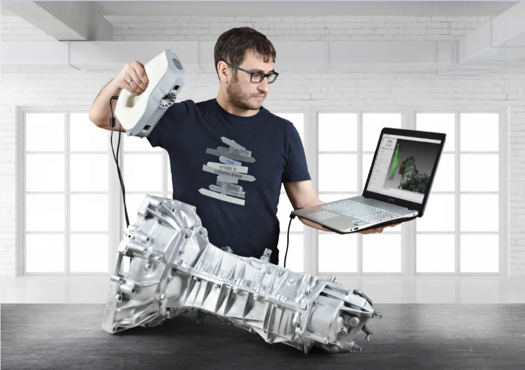
Artec Studio’s documented six-stage backbone is Scanning, Cleaning, Alignment, Registration, Fusion, and Postprocessing. That is a scan-to-mesh workflow, not the whole reverse-engineering job, but it is the right foundation. In practice, Artec Eva scan-to-CAD means capturing usable data, cleaning it, stabilizing alignment, building a mesh, checking that mesh for drift or gaps, and only then deciding how to extract sections, primitives, surfaces, or references for CAD remodeling. The scan is usually the measurement substrate, not the finished engineering model. Reverse engineering still requires judgment about feature intent, symmetry, datums, and tolerances. [3] [5] [7]
Artec separates mesh-style outputs from CAD-oriented outputs. Eva’s published export list includes OBJ, PLY, WRL, STL, AOP, ASC, Disney PTX (PTEX), E57, and XYZRGB for 3D mesh data, plus STEP, IGES, and X_T for CAD, and CSV, DXF, and XML for measurements. Artec Studio also documents direct export of models, CAD primitives, and cross-sections to SolidWorks. That supports section-based and primitive-based reverse-engineering workflows, but it does not mean one-click creation of a complete native parametric feature tree from arbitrary scan data. [1] [5]
A good result is not just a clean mesh. It is a documented workflow: capture settings saved, processing choices recorded, registration quality reviewed, and the resulting geometry checked against known dimensions or a reference measurement method. Artec’s processing documentation is useful here because it defines max mesh resolution as a grid-step parameter, which helps avoid a common mistake: treating a denser mesh as proof of better dimensional truth. [4]
Typical scan-to-CAD pipeline:
- Prepare the part and scene, including surface treatment or added tracking features if the part needs them. [3]
- Capture full coverage with deliberate overlap and an intentional tracking mode choice. [2] [3]
- Clean obvious noise, fixtures, and unwanted surroundings. [3]
- Align scans into a common coordinate frame. [3]
- Run global registration to optimize frame positions across the scan set. [3]
- Fuse the data using a realistic model resolution; for Eva scans, Artec’s Autopilot guidance says the resolution should be no less than 0.5. [3] [4]
- Inspect the result for drift, holes, local mismatch, and incomplete geometry.
- Extract sections, primitives, or surfaces, then export to CAD or remodel downstream as needed. [5] [7]

Artec Eva vs Artec Space Spider vs Artec Spider II for reverse engineering
Space Spider is the legacy high-detail reference in this comparison, while Spider II is the current fine-detail Artec option. Artec’s Spider II press release is dated September 9, 2024, and explicitly says Spider II is building on the success of Artec Space Spider. That matters because many buyers still search for “Eva vs Space Spider,” but a current comparison should treat Spider II as the active successor-class option for smaller, more detailed work within Artec’s handheld structured-light range. [8] [9] [10]
Outside Artec, the category shifts again. If the job is driven by verification tolerance rather than model generation, metrology-grade handheld laser systems sit in a different class. A HandySCAN 3D BLACK Elite example publishes 0.025 mm accuracy and 0.020 mm + 0.040 mm/m volumetric accuracy, which helps explain why “best” depends on scanner class, not brand loyalty. [16] [17]
| Decision factor | Artec Eva | Artec Space Spider (legacy) | Artec Spider II (current) |
|---|---|---|---|
| Published accuracy | Up to 0.1 mm. [1] | Up to 0.05 mm. [8] | Up to 0.05 mm. [9] |
| Published resolution | Up to 0.2 mm. [1] | Up to 0.1 mm. [8] | Up to 0.05 mm. [9] |
| Accuracy over distance | Up to 0.1 mm + 0.3 mm/m. [1] | Up to 0.05 mm + 0.3 mm/m. [8] | Up to 0.05 mm + 0.3 mm/m. [9] |
| Minimum object size / intended scale | Starting from 10 cm; medium-sized parts and broader freeform coverage. [1] | Starting from 5 mm; small detailed parts. [8] | S–M scanning range with 1,800 cm³ capture zone for closer-range detail work. [9] |
| Working distance / FOV implications | 0.4–1 m with 214 × 148 mm to 536 × 371 mm field of view. [1] | 0.2–0.3 m with 90 × 70 mm to 180 × 140 mm field of view. [8] | 0.19–0.3 m with 128 × 104 mm to 171 × 152 mm field of view. [9] |
| Speed / throughput indicators | Up to 16 FPS; up to 18 mln points/s. [1] | Up to 7.5 FPS; up to 1 mln points/s. [8] | Up to 30 fps; up to 8 mln points/s. [9] |
| Best-fit RE use cases | Medium-to-large parts, faster coverage, mesh and CAD-reference workflows. | Small features, intricate surfaces, legacy fine-detail work. | Small-to-medium parts needing more detail than Eva with current-product support. |
| Primary limitations | Not ideal for the smallest features or the strictest verification-heavy jobs. [1] [13] | Older platform and narrower capture envelope for broad coverage tasks. [8] | Closer-range detail scanner, not a general substitute for Eva on larger coverage jobs. [9] |
The practical readout is simple. Eva is the broader-coverage tool. Space Spider is the older fine-detail reference point. Spider II is the current Artec choice when the job needs more detail than Eva but still fits a close-range structured-light handheld workflow. If the reverse-engineering brief is dominated by strict verification or finer-feature capture than this class comfortably supports, the comparison should shift to metrology-oriented handheld laser systems instead of staying within the same product family. [9] [10] [16]
The main rule is scale first, brand second. Choose Eva when part size and documentation goals favor speed and coverage. Choose Spider II when finer detail matters and the scan volume is smaller. Choose a metrology-grade class when verification tolerance, not just model generation, is the governing requirement. [1] [9] [16]
Limitations, failure modes, and risk controls
Optical surface issues. Artec’s guidance says transparent, reflective, and black objects may need powder coating or anti-glare spray before scanning. For simple monochrome geometry, it also suggests adding auxiliary objects or markers in the scene. These are not cosmetic tips. They are ways to make the projected pattern and the tracking features readable enough for reliable geometry capture and stable alignment. If the optical response is poor, the result can include missing data, ragged edges, noisy surfaces, or frame-to-frame instability. NIST’s broader warning fits here as well: structured-light scanners have multiple error sources, and surface behavior is one of the variables that can break the link between controlled specifications and real-world results. [3] [13]
Line-of-sight geometry issues. Deep pockets, undercuts, hidden recesses, and thin edges remain difficult for optical scanning because the system cannot reconstruct what it cannot see or illuminate from a usable angle. A part can look complete in the viewport and still contain holes, softened edges, or distorted geometry in shadowed regions. More confidence on screen does not solve an occlusion problem; coverage planning and extra viewpoints do. [13]
Tracking and alignment issues. Artec Studio supports target-assisted workflows, and its documented tracking modes give you options for geometry, texture, or targets, but long scans and repetitive surfaces can still drift. The software can help, and targets can improve tracking and registration, yet neither removes the need for independent checking. In reverse engineering, the safest habit is to verify the reconstructed result against known dimensions or a reference measurement method before the model becomes design input. [2] [4] [13]
Mitigation checklist:
- Matte spray or powder for transparent, reflective, or black surfaces. [3]
- Temporary texture or added background objects when geometry is too uniform. [3]
- Targets where appropriate for tracking stability or larger jobs. [2]
- Stable fixturing so the part does not move during capture.
- Reference artifacts or known features to check alignment and scale.
- Verification against calipers, a CMM, or known dimensions before the model is trusted for CAD or inspection use. [13]
Standards and verification: what VDI/VDE 2634 and ISO 10360-13 do — and don’t — guarantee
VDI/VDE 2634 Blatt 2:2012-08 is withdrawn, and its scope is narrower than many buyers assume. The DIN Media listing says it applies to picture-giving optical 3D measuring systems using triangulation in a single elementary measuring procedure, or “single view,” and explicitly says systems that transform several single views into an object coordinate system by repositioning the sensor and/or object are not covered by that guideline. That is why it should not be used as a blanket claim that a handheld multi-view reverse-engineering workflow is somehow “certified” by itself. [11]
ISO 10360-13:2021 is the more relevant current reference point for optical 3D CMS acceptance and reverification testing, but it still applies under defined conditions. The ISO listing says it covers verification of measuring performance when surface characteristics such as glossiness and color are restricted and within a cooperative range. It is an acceptance and reverification framework, not a promise that every real part in every real setup will behave the same way. NIST’s warning bridges the standards language to shop reality: surface, geometry, and setup conditions may differ from test conditions, so part-level verification is still necessary. [12] [13]
Practical setup and workstation realities
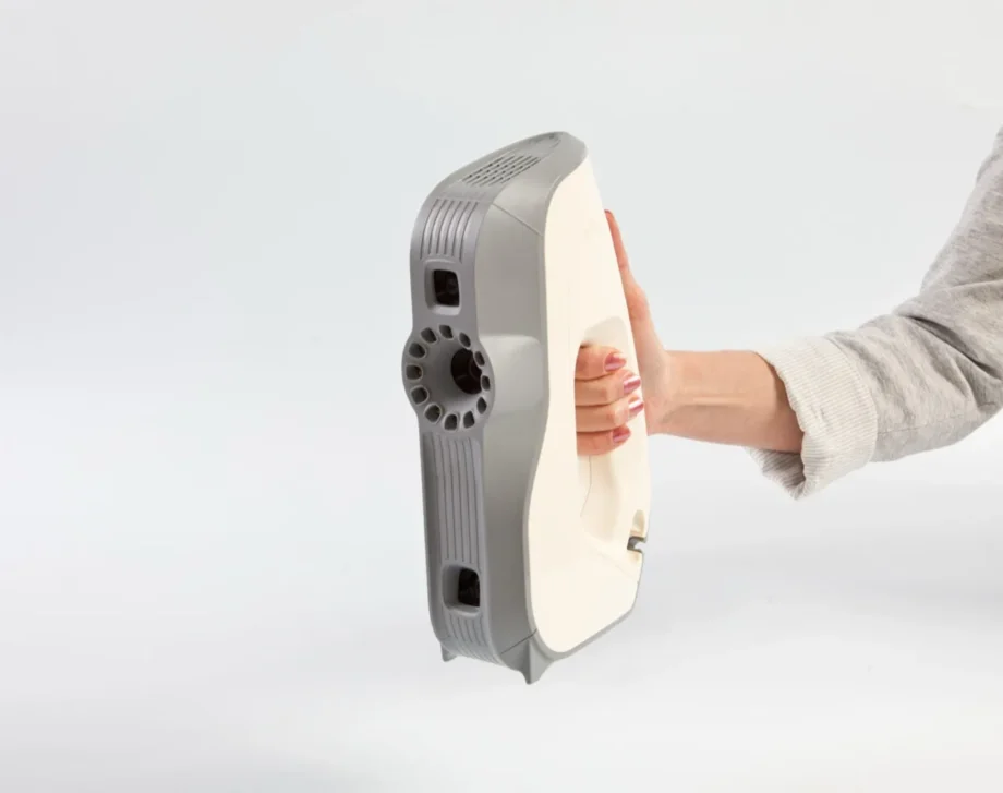
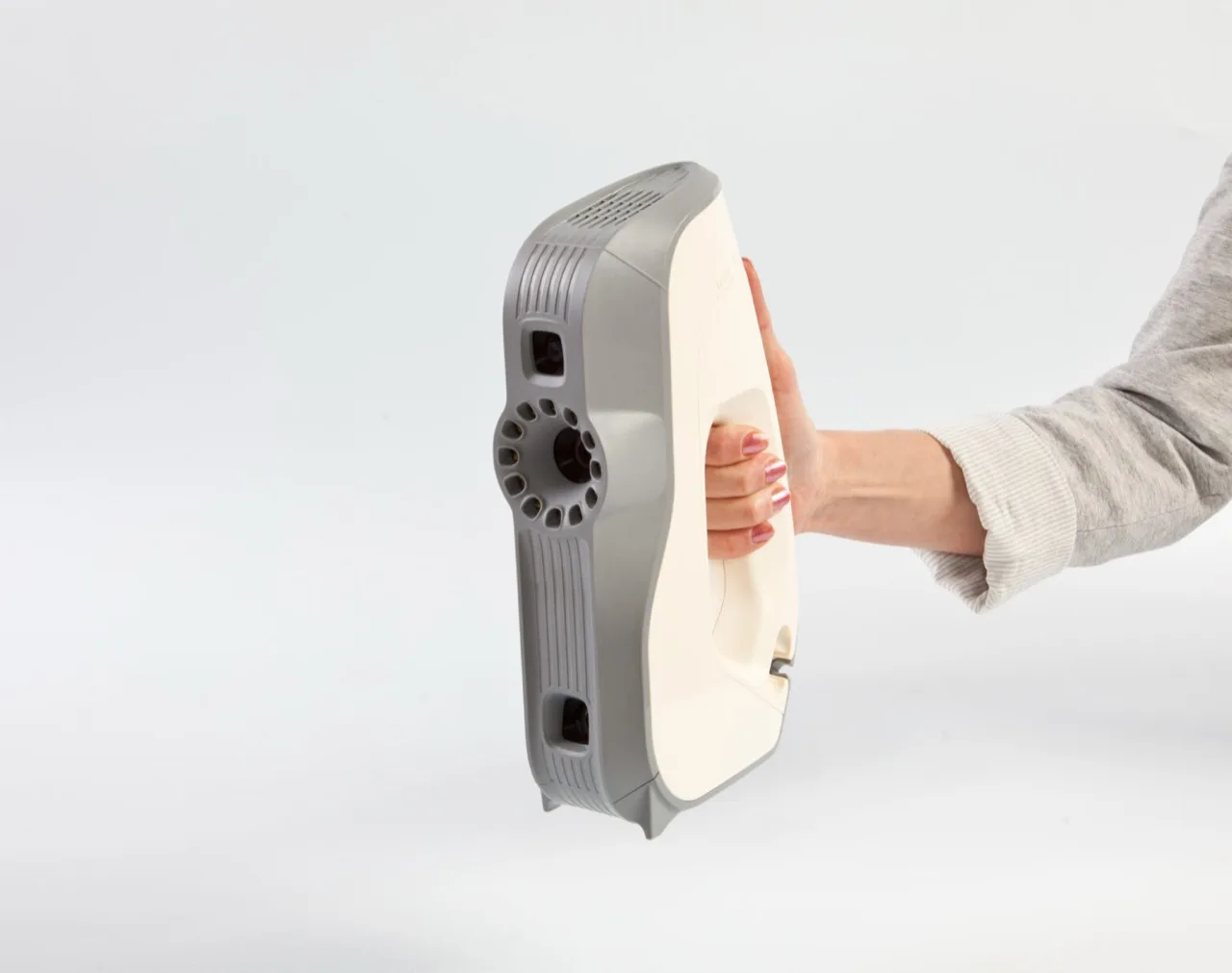
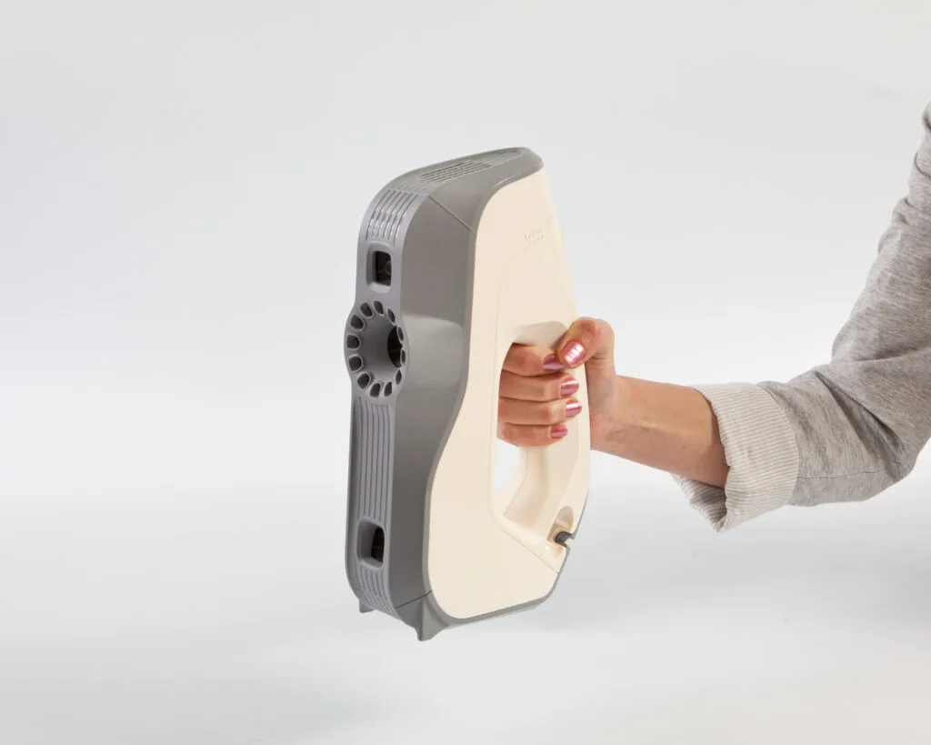
Artec Eva is a handheld unit with published dimensions of 262 × 158 × 63 mm and a listed weight of 0.9 kg / 2 lb. That is the number to use if weight matters, because the same product page also contains marketing copy describing the scanner as 0.85 kg. For planning purposes, treat 0.9 kg as the published specification and 0.85 kg as page-level copy drift. [1]
Workstation planning matters almost as much as scanner planning. Artec’s current support page lists Windows 8.1, Windows 10 x64, and Windows 11 support, explicitly says macOS is not supported, and gives RAM guidance of 16 GB minimum for Eva in SD mode, 32 GB+ minimum for Eva in HD mode, and 64+ GB recommended. Artec’s HD documentation also says HD reconstruction requires a powerful Nvidia video card and sufficiently large RAM. In practice, Eva is not just a scanner purchase; it is a scanner-plus-workstation decision, especially if you expect larger meshes, HD processing, or repeat project work. [2] [6]
Spec drift and why older reviews can mislead reverse-engineering decisions
Older third-party reviews can preserve a useful historical snapshot, but they may not match current manufacturer figures. All3DP’s Artec Eva review, updated on April 16, 2020, listed resolution up to 0.5 mm and data acquisition speed up to 2 million points per second. Artec’s current product page lists up to 0.2 mm resolution and up to 18 mln points/s instead. For reverse engineering, that gap is large enough to change how you judge fit, especially if you are comparing older summaries against current official specs. [1] [18]
The editorial rule is simple: verify the current official specification first, then use older third-party material only as context for drift, not as the basis for a present-tense decision. That source hierarchy matters whenever a scanner is being evaluated for tolerance-sensitive work, because the headline figures attached to the same product name can change over time. [1] [18]
Verdict: Is Artec Eva the best 3D scanner for reverse engineering?
Artec Eva can be a strong candidate for the best 3d scanner for reverse engineering when the deliverable is a medium-to-large part, the goal is a CAD reference model rather than strict metrology-grade verification, and the surface can be captured and checked reliably. Its published specs support that use case, but they do not make it the universal answer. [1]
The decision rule is straightforward: match scanner class to part scale, required feature size, surface behavior, workflow speed, and verification plan. Eva is often a strong fit for scan-to-CAD work because it combines handheld coverage with published specs of up to 0.1 mm accuracy, up to 0.2 mm resolution, and starting object size from 10 cm. But tighter figures published by metrology-grade and hybrid alternatives show why Eva is not automatically the best choice for every tolerance-critical or fine-feature job. If the work is dominated by small intricate geometry or verification-heavy acceptance, a higher-detail or more metrology-oriented class is the safer choice. [1] [16] [17]
FAQ
What is the best 3D scanner for reverse engineering?
There is no single best 3D scanner for reverse engineering in every case. The right class depends on part size, required detail, surface condition, throughput needs, and how the result will be verified. Eva is often a fit for medium-sized to larger scan-to-CAD work, while smaller features or stricter verification needs can push the decision toward higher-detail or metrology-oriented systems. [1] [13] [16]
Is Artec Eva good for reverse engineering?
Yes, if the part is medium to large, the geometry is not extremely fine, and the output is a usable scan reference rather than a final inspection verdict. Eva’s published specs and Artec Studio workflow make it a practical input for many reverse-engineering jobs, but the result still depends on surface preparation, tracking stability, operator technique, and verification. [1] [3] [13]
What is scan-to-CAD, and what is it not?
Scan-to-CAD is the workflow of capturing a physical part, processing the scan data, and using that geometry to create sections, surfaces, fitted primitives, or remodelled CAD. It is not a guarantee of one-click conversion from raw scan to a perfect native parametric model. In most real jobs, engineering judgment is still needed after scanning. [3] [5] [7]
How do you use Artec Eva for scan to CAD in practice?
The short version is: prepare the part, capture enough overlap, clean the scans, align and register them, fuse the data, inspect the mesh for drift or holes, then extract the sections or geometry your CAD workflow needs. Artec’s documentation supports direct export of CAD primitives and cross-sections, but downstream remodeling is often still part of the job. [3] [5] [7]
Artec Eva vs Artec Space Spider vs Spider II for reverse engineering — which should you choose?
Choose Eva when you need broader coverage and faster work on medium-sized or larger parts. Choose Space Spider only as a legacy reference point for older comparisons. Choose Spider II when the part is smaller and the job needs finer detail in Artec’s current handheld structured-light range. If verification tolerance is the driver, compare against metrology-grade handheld laser systems instead of staying inside the same family. [8] [9] [10] [16]
Can Artec Eva scan black or shiny parts, and when do you need spray or targets?
It can, but those surfaces are also where structured-light scanning becomes more conditional. Artec’s guidance recommends powder coating or anti-glare spray for transparent, reflective, or black objects, and suggests auxiliary objects or markers for simple monochrome geometry. Targets can also help when tracking stability matters more than setup speed. [2] [3] [13]
What does 0.1 mm + 0.3 mm/m accuracy over distance mean for a 1 m-long part, and how should you verify the result?
It means the published manufacturer formula has a fixed term plus a length-dependent term. Over a 1 m span, the distance term adds 0.3 mm to the 0.1 mm fixed term, so the simplified implication is about 0.4 mm before other real-world effects are considered. That is not a guaranteed total error for your part. It is a published spec that still has to be checked against your geometry, setup, and verification method. [1] [13]
Related on 3D Mag
- Artec Spider II: the best 3D scanner for prosthetics and orthotics
- Artec Jet: the best 3D scanner for shipbuilding and vessel refit
Sources
- 1. Artec Eva product/specs page — manufacturer
- 2. Artec Studio 20 docs: Scanning — official documentation
- 3. Artec Studio 20 docs: Quick guide / workflow / Autopilot — official documentation
- 4. Artec Studio 20 docs: Data Processing — official documentation
- 5. Artec Studio 20 docs: Projects/Export — official documentation
- 6. Artec Support: Eva system requirements — official documentation
- 7. Artec Support: DXF sections export — official documentation
- 8. Artec Space Spider legacy page — manufacturer
- 9. Artec Spider II product/specs page — manufacturer
-
- Artec Spider II press release — manufacturer news
-
- DIN Media listing for VDI/VDE 2634 Blatt 2 — standard
-
- ISO listing for ISO 10360-13:2021 — standard
-
- VIM3 entry 2.13 Measurement accuracy — scientific
-
- VIM3 entry 2.15 Measurement precision — scientific
-
- Creaform HandySCAN 3D BLACK Elite page — manufacturer
-
- EinScan HX specs — manufacturer