
Summary
Point cloud to BIM is the process of turning measured scan data from an existing building into a semantic, object-based BIM model that represents as-built conditions. In practice, scan to BIM is not a single conversion. It is a chain of decisions that runs from requirements to capture, registration, preparation, modeling, QA, and delivery. That framing matches both classic literature on as-built BIM creation, which separates data collection, data preprocessing, and BIM modeling, and later requirements-first frameworks that begin with information requirements and required scan data quality before reconstruction starts. [1] [2]
Historical background: from measured drawings to scan to BIM
Existing buildings have always needed as-built or as-is documentation, so measured drawings, tape measurements, and field surveys were the traditional way to record what was actually there. In practice, those records were often incomplete, slow to update, or disconnected from later building changes. [1]
Scan to BIM emerged because reality capture could gather much denser spatial evidence than sketching or manual measurement alone. But denser evidence did not remove interpretation. Early reviews still describe manual creation of as-built BIM as time-consuming, subjective, and error-prone, because the point cloud must be reconstructed into objects, relationships, and modeling decisions rather than merely copied forward. The workflow changed where the effort sits: less time measuring isolated points, more time deciding what the measured evidence means. [1]
What a point cloud is — and why it is not yet BIM
A point cloud is measured spatial evidence: a set of 3D points, often with attributes such as color or intensity, that records surfaces and spaces but does not assign building semantics on its own. BIM is different. In BIM, a wall is not just a group of surfaces; it is a volumetric object with an identity, relationships to adjacent elements, and properties that can be queried or exchanged. That semantic boundary is why point cloud to BIM is a reconstruction workflow rather than a file conversion. A mesh may make geometry easier to view or process, but meshing alone does not convert scan data into BIM. For the same reason, “point cloud BIM” is only shorthand: the cloud is the evidence layer, while the BIM model is the interpreted result. E57 sits on the evidence side of that boundary, because it stores 3D point data, attributes such as color and intensity, and 2D imagery rather than BIM object semantics. [1] [7]
| Data type | What it contains | What it does not contain | Typical role in scan to BIM |
|---|---|---|---|
| Point cloud | Measured points, plus optional attributes and imagery | Building object identity or relationships | Evidence from reality capture |
| Mesh | Connected geometry derived from points | Native BIM semantics | Visualization or intermediate processing |
| CAD | Drafted geometry, often lines or surfaces | Object intelligence and relationships | 2D/3D drafting and documentation |
| BIM | Objects, properties, and relationships | Raw scan measurements | Authoritative model for downstream use |
Reality capture methods that feed point cloud BIM
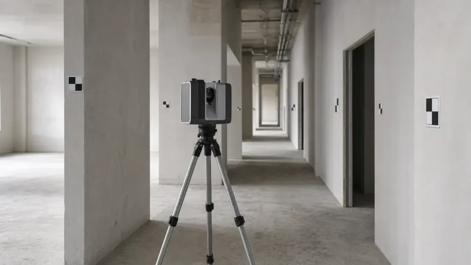
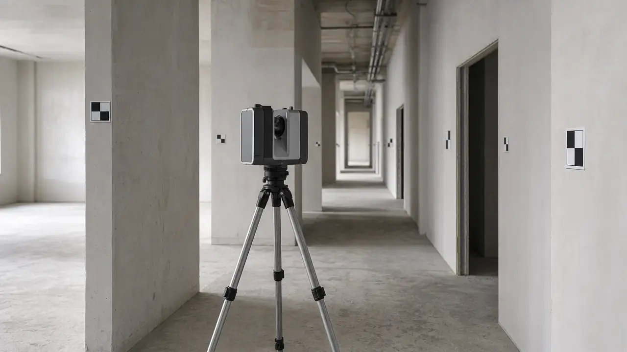
Terrestrial laser scanning, or TLS, remains the baseline method when a project needs controlled geometry, survey tie-in, and dense coverage of a mostly static scene. It is the most familiar path into laser scan to BIM because multiple stations can be planned around overlap and control. NIST’s review places typical TLS performance in broad context: measuring ranges from a few tens to a few hundreds of meters, range errors from sub-millimeter to several millimeters, range noise on the order of a few hundred micrometers, and angle uncertainties on the order of tens of arc-seconds. Those figures are context, not a promise for any one scanner or project. [14]
Mobile SLAM mapping is useful when speed and coverage matter more than strict static control, especially along long interior routes where setup time dominates. Its tradeoff is drift sensitivity. Loop closures matter because they can significantly affect performance, while dynamic environments and transparent or reflective surfaces can break tracking or reduce consistency. That makes SLAM valuable for fast interior documentation and exploratory capture, but not a substitute for a control-based survey when the model has to be tightly anchored to a project coordinate frame. [20]
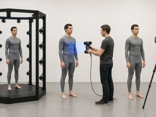
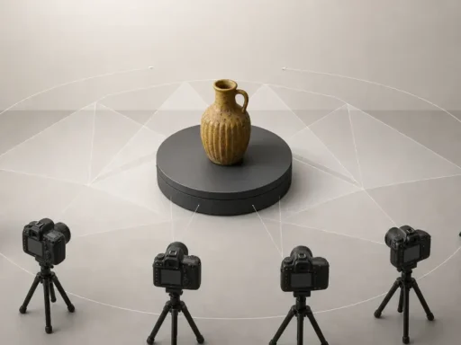
Photogrammetry complements both methods when imagery can describe surfaces that a scanner may miss, and close-range or structured-light systems are useful for smaller objects or localized high-detail zones. The failure modes differ from TLS. In construction-oriented photogrammetry literature, error depends on camera internal parameters, imaging distance, baseline, overlap, viewing angles, and processing software, so capture geometry and workflow choices matter as much as the camera itself. In practice, the best method is the one that matches the scene, the required control, and the reconstruction target. [19]
| Method | Strengths | Common failure modes | Coordinate-control notes |
|---|---|---|---|
| TLS | Dense geometry, stable survey tie-in | Occlusion, setup time, reflective surfaces | Best when control and repeatability matter |
| SLAM mobile mapping | Fast coverage, good for interiors | Drift, weak loop closure, dynamic scenes | Needs careful frame handoff and QA |
| Photogrammetry | Rich texture, flexible capture | Image noise, poor overlap, lighting and processing sensitivity | Needs strong image geometry and control |
| Close-range / structured light | Fine detail at small scale | Short working distance, occlusion, surface sensitivity | Best for local detail rather than whole-building capture |
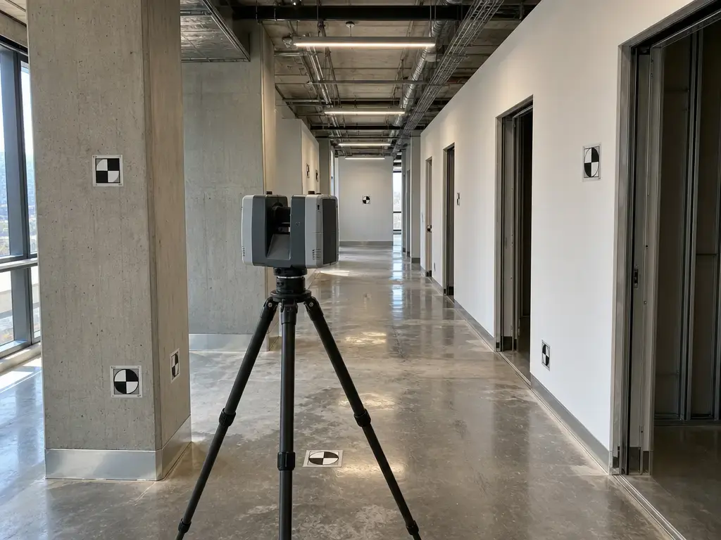
Point cloud to BIM workflow: from field capture to building model
A point cloud to BIM workflow works best when the intended use is defined before scanning begins, because information requirements determine scan coverage, required data quality, and how much reconstruction is justified. That logic appears in both the classic three-phase framing of as-built BIM creation and the later application-oriented framework that starts with information requirements, then required scan data quality, then acquisition, and finally as-is BIM reconstruction. [1] [2]
In production, the process moves from evidence to interpretation to authoring. Tang’s review further divides the modeling task into geometric modeling, object recognition, and object relationship modeling, which is a useful reminder that BIM means more than fitting surfaces. Segmentation helps separate regions or likely objects, classification assigns meaning, and authoring turns the interpreted evidence into elements with categories, parameters, and relationships. The sequence looks linear, but real projects are iterative: teams often move backward when coverage, alignment, or scope proves insufficient. [1]
- Define the BIM use and information requirements, including LOIN and LOD expectations.
- Build the scan plan around those requirements, including coverage, control, and density.
- Capture the site or asset.
- Register the scans into one coordinate frame.
- Treat registration QA as an acceptance gate before modeling begins.
- Clean, crop, and organize the cloud, using segmentation and classification where appropriate.
- Link or index the cloud in the BIM authoring environment.
- Model elements and assign categories, parameters, and relationships.
- Validate the model against the cloud.
- Deliver the package defined by scope.
Registration and coordinate systems — make QA a gate before modeling
Registration is the point where separate scans become one usable evidence set, but a good local fit does not guarantee global correctness. A doorway may look clean while the far end of a building has accumulated drift, especially in repetitive geometry, weak overlap, or mobile mapping datasets. Residuals are therefore not the same thing as true whole-building correctness. ISO 17123-9 is useful as a repeatability-focused field verification method, but its scope is narrower than full project acceptance or comprehensive performance evaluation. That is why registration should be treated as a gate before BIM modeling, not as a cosmetic alignment step. [16] [20]
Coordinate systems belong in the same QA conversation. A local project frame, survey control, and any geodetic reference all need a clear handoff so the cloud remains tied to intended as-built conditions after export, import, and model sharing. If that transform chain is unclear, the cloud can appear aligned in one application and shift in another. This matters even more because acceptable error depends on use case; NIST’s TLS review shows that tolerance needs across 3D imaging applications range from a few tens of millimeters to a few tens of micrometers, so “good enough” has to be defined in project terms rather than assumed from a generic workflow. [14] [16]
Pre-modeling registration QA evidence to review
- target or control checks
- cloud-to-cloud residuals
- loop closure or drift checks for SLAM
- overlap sufficiency
- coverage gaps and occlusions documentation
- coordinate system definition and transform handoff
These checks are evidence, not assumptions. If the registration evidence is weak, modeling should stop until the acceptance checkpoint is met. [16] [20]
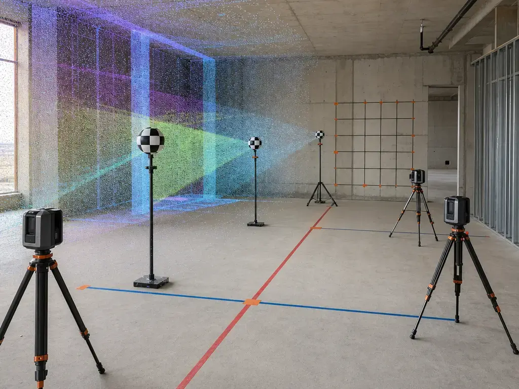
Accuracy, point spacing, LOD, and Level of Information Need (LOIN) — the accuracy stack
One number never describes the whole chain from instrument behavior to model acceptance. In point cloud to BIM, the useful stack runs from scanner performance to ranging noise, point spacing, registration residuals, control-network accuracy, local fit error, global or volumetric accuracy, model tolerance or deviation, and finally acceptance tolerance. NIST cautions that terms such as accuracy and precision are qualitative concepts and should not be used loosely as quantitative labels, while the international vocabulary of metrology notes that measurement precision is often mistakenly used to mean measurement accuracy. A disciplined project brief should therefore ask what quantity is being discussed at each stage, rather than collapsing all performance into one “accuracy” claim. [17] [18]
| Term | What it means in practice | Why it matters |
|---|---|---|
| Instrument spec/performance | Manufacturer or test performance of the scanner | Sets the starting envelope |
| Ranging noise | Variation in individual distance measurements | Affects point scatter |
| Point spacing | Distance between neighboring points | Limits visible detail |
| Registration residuals | Misfit after aligning scans | Shows alignment quality |
| Control-network accuracy | Accuracy of survey control | Anchors the coordinate frame |
| Local fit error | Mismatch in a modeled element area | Checks authoring quality |
| Global/volumetric accuracy | Error across a larger area or volume | Reveals accumulated drift |
| Model tolerance/deviation | Difference between model and evidence | Used for validation |
| Acceptance tolerance | Contractual limit for pass/fail | Defines delivery acceptance |
LOD and LOIN are related but not interchangeable. LOIN, formalized in ISO 7817-1:2024, is a methodology for specifying level of information need and information deliveries. LOD, by contrast, remains element-focused industry guidance; BIMForum’s current public specification is Version 2025 Part I, and EN 17412-1 context also clarifies that LOD relates to model elements rather than complete models. Neither framework, by itself, defines whether a scan-based reconstruction is accurate enough for a given project. [12] [13] [22]
The hard rule is simple: no universal scan-to-BIM tolerance found. Tolerance has to be project-specific, use-case-specific, and contract-defined. Published application needs in 3D imaging range from a few tens of millimeters to a few tens of micrometers depending on the task, so borrowing a number from another domain is not a safe acceptance method. If a sampling approach is used, NISTIR 7638 provides one illustrative example: tolerance T = 13 mm, maximum percent defective P = 10%, and sample size n = 200. That is an example of statistical acceptance logic, not a universal threshold for scan to BIM. [14] [21]
Modeling BIM elements from point cloud evidence
Some building parts are relatively tractable to model from visible evidence, especially where geometry is exposed and regular. Walls, slabs, columns, and primary structure are often easier to reconstruct than systems with dense intersections or partial visibility. What moves the result from geometry toward BIM is not just surface fitting, but the combination of geometric modeling, object recognition, and object relationship modeling. That is where categories, adjacency, hosting, and parameters start to matter. [1]
Other categories remain difficult because the cloud only shows what the sensor could see. Congested MEP runs, high or poorly covered zones, reflective or transparent surfaces, and hidden services are common problem areas. The practical rule is to model what the evidence supports and keep interpretation visible in scope. Materials, internal build-ups, and concealed routing cannot be inferred reliably from visible point data alone. That is one reason manual reconstruction is still described as time-consuming, subjective, and error-prone even when the capture itself is excellent. [1]
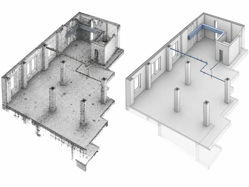
Deliverables and file formats (E57 vs RCP/RCS vs IFC vs native BIM)
E57, RCP/RCS, native BIM files, and IFC do different jobs in a scan to BIM workflow. ReCap supports export to E57, PTS, and RCP/RCS, while structured E57 export can preserve individual scans, row and column information, and registration transforms as a complete export without deletions or clips. An RCP project file, by contrast, references point-cloud data and does not contain it, so its dependent RCS files have to travel with it. ASTM E2807-11(2026) defines E57 as a 3D imaging data exchange format capable of storing 3D point data, attributes such as color and intensity, and 2D imagery; standardized quantities are expressed in SI units, with planar angles in radians. [5] [6] [7]
IFC deserves separate treatment because it is not a point-cloud format. ISO 16739-1:2024 defines the IFC data schema, while buildingSMART documents IFC as a combination of schema, documentation, property and quantity sets, and exchange structures. Its prevalent exchange form remains STEP Physical File, though other exchange structures also exist. In practice, IFC exports are mappings from one data structure to another, so what survives the handoff depends on software and workflow. None of that turns IFC into raw scan data; it is a BIM exchange structure. [8] [9] [10]
Typical deliverables include:
- registered cloud
- native model
- IFC
- 2D drawings
- deviation report
- asset dataset
The table below summarizes scope boundaries for the main standards and guidance often mentioned around scan to BIM. None of them alone is a scan-to-BIM conversion quality standard. [7] [8] [11] [12] [16] [22]
| Standard or guidance | What it governs | What it does not govern |
|---|---|---|
| ISO 19650-1:2018, confirmed 2024 | Information management concepts and principles | Scan accuracy specification |
| ISO 16739-1:2024 | IFC data schema | Scan acquisition or registration quality |
| ISO 7817-1:2024 | Level of information need methodology and information deliveries | Scanner performance |
| ASTM E2807-11(2026) | E57 3D imaging data exchange | BIM semantic modeling |
| ISO 17123-9:2018 | Field procedures for testing terrestrial laser scanners | Project acceptance criteria |
| BIMForum LOD Specification, Version 2025 Part I | LOD guidance for model elements | Complete scan-to-BIM conversion quality |
Quality control and validation against the cloud
Validation has to be scoped before modeling begins. The tolerance basis, sampling strategy, excluded or occluded zones, and reporting format all shape what “done” means. The point cloud is the reference evidence, so the model should be checked against it with deviation reports, spot-check dimensions, and clear notes on where the cloud was incomplete or ambiguous. In tool terms, point clouds are commonly handled as linked reference data rather than embedded model content, which makes document control and path management part of quality control as well as geometry control. [3] [4]
If sampling is used, example thresholds should stay labeled as examples unless the contract explicitly adopts them. One illustrative setup in NISTIR 7638 uses T = 13 mm, maximum percent defective P = 10%, and sample size n = 200. That is useful as a reminder that acceptance can be statistical, but it is not a universal scan-to-BIM tolerance. NIST’s metrology guidance also favors careful, uncertainty-aware language over vague claims of “accuracy” or “perfect fit,” which is a better basis for reporting model-to-cloud agreement. [17] [21]
Applications: where scan to BIM is used — and when full BIM is unnecessary
Scan to BIM is most useful when existing conditions have to be carried into a model for renovation, retrofit, coordination, industrial plant work, heritage recording, or facility management. In each case, the intended application should be defined first, because it drives required scan data quality and reconstruction scope. That is why the same reality capture dataset can support very different outcomes, from a lightweight coordination model to a richer asset-information handoff. [2]
Sometimes a registered point cloud plus drawings is sufficient. If the task is limited to layout checking, progress comparison, dimensional review, or a one-off examination of as-built conditions, full semantic reconstruction may not be justified. In those cases, the cloud remains the primary record and the model should be limited to whatever the decision actually needs.
Limitations and common failure points
The main limitations in point cloud to BIM are a mix of sensing, geometry, software dependency, and project definition. Occlusion leaves gaps behind walls, equipment, or ceiling congestion. Reflective and transparent surfaces can produce unstable or missing data. SLAM-based capture can drift or fail in dynamic, transparent, or reflective environments, especially when loop closure is weak, and photogrammetry brings its own image-geometry sensitivities because camera parameters, overlap, baseline, distance, and processing choices all affect the result. Large point clouds can reach hundreds of millions to billions of points, so performance, clipping, indexing, and review discipline matter. Linked-reference behavior creates another risk: Revit links point clouds rather than embedding them, and RCP files reference RCS files rather than containing them, so broken paths can make a technically sound deliverable unusable. Coordinate mismatch, hidden services, over-modeling beyond the required LOD or LOIN, and vague acceptance criteria can all turn a valid survey into a poor contractual handoff. [3] [6] [19] [20]
- Check coverage, alignment, and coordinate control before modeling.
- Confirm that linked references, file dependencies, and deliverable formats will survive transmittal.
- Set LOD and LOIN only to the level the use case needs.
Current research and market context: automation as assistive, not autonomous
Current scan to BIM research is pushing automation into narrower tasks inside the pipeline, especially segmentation, classification, instance recognition, and parametric reconstruction, rather than eliminating the whole modeling process. A 2026 review reports a systematic analysis of 58 documented scan-to-BIM cases and summarizes four-step guidelines for adopting automated scan-to-BIM processes. That is a useful sign of maturing research structure, but not evidence that the end-to-end workflow has become automatic. [23]
That production reality matters because the older bottlenecks have not disappeared. The literature still describes manual as-built BIM creation as time-consuming, subjective, and error-prone, which is exactly why automation is being aimed at repetitive subtasks first. In practice, software can assist reconstruction and reduce some manual effort, but scope definition, registration QA, coordinate control, and final model review still require human judgment. Automation supports the pipeline; it does not determine project acceptance. [1] [23]
Practical guidance: scope the model before you scope the scan
A scan to BIM workflow is easiest to control when the brief begins with intended use, required elements, LOIN and LOD expectations, coordinate system, excluded zones, validation criteria, and final deliverables. That follows the requirements-first logic in the literature: identify information requirements and required scan data quality before acquisition and reconstruction begin. ISO 19650-1 sits on the information-management side of that problem; it helps organize information exchange, but it does not define scan accuracy. [2] [11]
For professionals preparing scope, the practical rule is to state what must be modeled, what may be omitted, and which source of truth governs conflicts between the point cloud and other records. If someone asks for turnaround time or price, no reliable figure found; those values vary too much with scope, geometry, access, capture method, and deliverable package to support a universal benchmark. The same discipline applies to validation: specify the check, the acceptance rule, and the handoff package before capture starts.
Conclusion: when point cloud to BIM is worth it
Point cloud to BIM is worth it when the project needs an as-built model tied to a defined use case rather than only a visual record. The decision should be framed by information need, LOIN and LOD expectations, coordinate system, QA criteria, and final deliverables. Requirements-first planning matters because it determines what must be captured, how reliable the evidence must be, and how much interpretation is justified before anyone starts modeling. [2]
FAQ
What is point cloud to BIM?
Point cloud to BIM is the process of turning measured scan points into a building model with object meaning, not just shape. The point cloud is the evidence layer; the BIM model is the interpreted result. That is why a point cloud is not a BIM model by itself, even when it looks geometrically rich. [1] [7]
How do you convert a point cloud to a BIM model?
The short version is: define requirements, capture the site, register the scans, prepare the cloud, model the building elements, and validate the result against the evidence. In practice, this is a scan to BIM workflow with a registration QA gate before modeling, not a one-click conversion. [1] [2]
What is a scan to BIM workflow, and why should it start with requirements?
A scan to BIM workflow should start with requirements because intended use determines what has to be captured, how much scan data quality is needed, and how much reconstruction effort is justified. The literature’s requirements-first framing is meant to prevent both over-scanning and under-modeling. [2] [12]
Point cloud to BIM vs scan to CAD — what’s the difference?
Scan to CAD usually means tracing geometry from the cloud into drafting output. Point cloud to BIM goes further by reconstructing semantic building objects with categories, properties, and relationships. CAD can describe shape, but BIM is structured around identifiable building elements. [1]
What’s the difference between accuracy, point spacing, registration error, and tolerance?
They are related but not interchangeable. Point spacing describes sampling density. Registration error describes alignment misfit between scans. Accuracy concerns closeness to the value being represented, while tolerance is the allowable deviation defined by the project. The “accuracy stack” matters because one number cannot describe the whole chain. [17] [18] [21]
E57 vs RCP/RCS vs IFC — which one is the BIM deliverable?
They serve different roles. E57 is a scan-data exchange format for point data, attributes, and imagery. RCP/RCS organize or reference indexed point-cloud data. IFC is the BIM exchange schema used for modeled objects and their semantics. So the BIM deliverable is typically IFC or a native BIM file, not E57. [5] [6] [7] [8]
How do you validate registration before BIM modeling begins?
Validate registration by reviewing control checks, cloud-to-cloud residuals, overlap sufficiency, coverage gaps, coordinate system handoff, and, for SLAM datasets, loop closure or drift behavior. The key point is that low residuals alone do not prove whole-building correctness. Registration QA has to function as an acceptance gate before modeling starts. [16] [20]
Sources
- Tang, Huber, Akinci, Lipman, Lytle — Automatic reconstruction of as-built building information models from laser-scanned point clouds: A review of related techniques. https://tsapps.nist.gov/publication/get_pdf.cfm?pub_id=904018
- Wang, Guo, Kim — An application oriented scan-to-bim framework. https://research.polyu.edu.hk/en/publications/an-application-oriented-scan-to-bim-framework/
- Autodesk Revit Help — About Point Clouds. https://help.autodesk.com/cloudhelp/2024/ENU/Revit-Model/files/GUID-BD499295-84DD-4BDE-B60D-73008AFBC791.htm
- Autodesk Revit Help — Using Point Cloud Files in a Project. https://help.autodesk.com/cloudhelp/2025/ENU/Revit-Model/files/GUID-D179BB6C-5528-498F-9413-00237092C2FA.htm
- Autodesk ReCap Help — Supported File Formats. https://help.autodesk.com/view/RECAP/ENU/?contextId=supported_file_formats
- Autodesk Reality Capture Help — About Scan and Photogrammetry Files and Projects. https://help.autodesk.com/cloudhelp/ENU/Reality-Capture/files/Getting_Started/Supported_File_Formats/scan_photogrammetry.html
- ASTM — E2807-11(2026) Standard Specification for 3D Imaging Data Exchange, Version 1.0. https://store.astm.org/e2807-11r26.html
- ISO — ISO 16739-1:2024 Industry Foundation Classes (IFC) for data sharing in the construction and facility management industries — Part 1: Data schema. https://www.iso.org/standard/84123.html
- buildingSMART — IFC 4.3.2.0 Documentation: Scope. https://standards.buildingsmart.org/IFC/RELEASE/IFC4_3/HTML/content/scope.htm
- buildingSMART — IFC 4.3.2.0 Documentation: Introduction. https://standards.buildingsmart.org/IFC/RELEASE/IFC4_3/HTML/content/introduction.htm
- ISO — ISO 19650-1:2018 Organization and digitization of information about buildings and civil engineering works, including building information modelling (BIM) — Information management using building information modelling — Part 1: Concepts and principles. https://www.iso.org/standard/68078.html
- ISO — ISO 7817-1:2024 Building information modelling — Level of information need — Part 1: Concepts and principles. https://www.iso.org/standard/82914.html?browse=ics
- ANSI Webstore (DIN) — DIN EN 17412-1:2021 Building Information Modelling — Level of Information Need — Part 1: Concepts and principles. https://webstore.ansi.org/standards/din/dinen174122021
- NIST — Performance Evaluation of Terrestrial Laser Scanners – A Review. https://tsapps.nist.gov/publication/get_pdf.cfm?pub_id=930840
- ASTM — E2938 Relative-Range Measurement Performance of 3D Imaging Systems in the Medium Range. https://store.astm.org/standards/e2938
- ISO — ISO 17123-9:2018 Optics and optical instruments — Field procedures for testing geodetic and surveying instruments — Part 9: Terrestrial laser scanners. https://www.iso.org/standard/68382.html
- NIST — TN 1297 Appendix D1: Terminology. https://www.nist.gov/pml/nist-technical-note-1297/nist-tn-1297-appendix-d1-terminology
- JCGM — JCGM 200:2012 International vocabulary of metrology (VIM). https://cms.ifcc.org/media/158409/JCGM_200_2012.pdf
- Dai, Feng, Hough — Photogrammetric error sources and impacts on modeling and surveying in construction engineering applications. https://link.springer.com/article/10.1186/2213-7459-2-2
- Linus, Rueckert — Understanding why SLAM algorithms fail in modern indoor environments. https://arxiv.org/abs/2305.05313
- NISTIR 7638 — Guidelines for Accepting 2D Building Plans. https://www.govinfo.gov/content/pkg/GOVPUB-C13-6a2d8a3ccb28588b50d6b226b253ced6/pdf/GOVPUB-C13-6a2d8a3ccb28588b50d6b226b253ced6.pdf
- BIMForum — Level of Development Specification, Version: 2025, Part I. https://bimforum.org/wp-content/uploads/2026/01/LOD-Spec-2025-Part-I-Official.pdf
- You, Chen, Xue — Automated scan-to-BIM for construction digital transformation: existing approaches, practical considerations, and future directions. https://frankxue.com/pdf/you26automated.pdf