
Summary: support interface 3d printing in plain terms
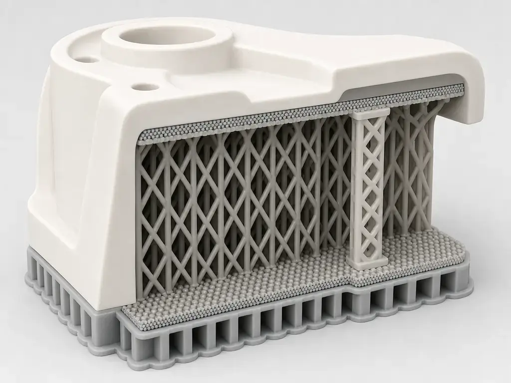
In support interface 3d printing, the support interface is the deliberately controlled contact region between a model and its supports, and the support roof is the dense top part of that region directly under an overhang. Slicers expose this through roof or interface settings plus Z-distance controls that leave clearance for removal later. [3] [4]
The trade-off is straightforward: a tighter, denser interface can improve the underside finish, but it usually makes supports harder to remove and can increase the chance of scars or partial fusing. In practice, you are adjusting three linked variables: geometry, meaning roofs, floors, and interface layers; clearance, meaning Z distance or support Z gap plus XY separation; and material, meaning whether the contact zone uses the same filament as the part or a different support interface material. Cura’s setting definitions and Prusa’s support guidance describe that balance in different UI language. [3] [4] [5]
Terminology note: interface geometry vs clearance vs interface material
In this article, support interface is a broad explanatory label, not one exact slicer checkbox. First, there is interface geometry: the dense contact region itself, such as a support roof under the model or a support floor where support starts on top of the model. Second, there are clearance controls: top and bottom Z distance plus XY separation, which decide how closely that geometry approaches the part. Cura separates these ideas into roof, floor, interface thickness, interface density, top distance, bottom distance, and X/Y distance settings, while Bambu defines Top Z Distance as the vertical distance between the top of the support interface and the model underside. [4] [5]
Third, there is interface material. That is not the same as changing a gap. Some slicers and multi-material systems let the support body and the support interface use different filaments, so the contact zone can behave differently from the bulk support below it. Bambu’s manual explicitly separates the support base from the support interface and notes that they can use different filaments, while Prusa documents separate support-material interface behavior and zero-contact workflows for synchronized soluble or breakaway setups. So a “better interface” might mean denser geometry, a different clearance, a different material, or a combination of all three. [3] [5]
What is a support interface in 3D printing?
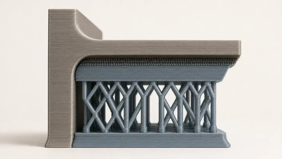
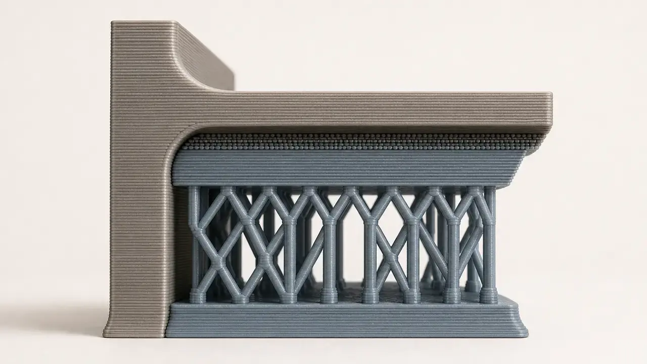
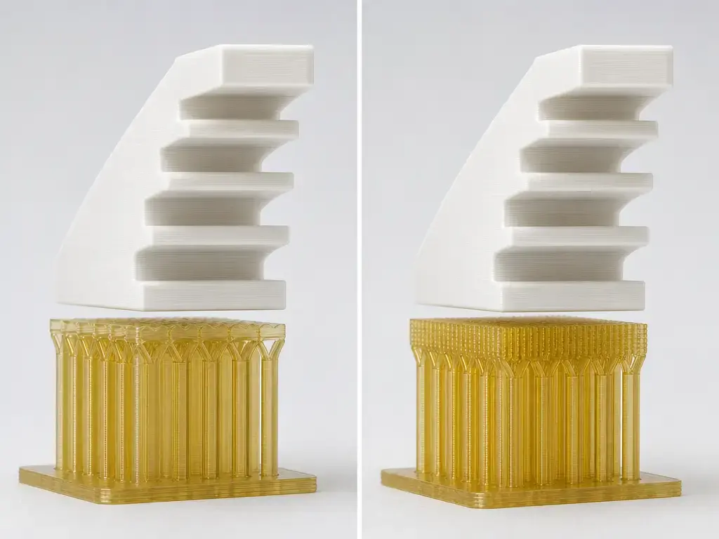
A support interface is the dense transition zone between the coarse support body and the part surface above it. In FFF printing, that usually means extra roof or floor layers, tighter line spacing, or a different interface material at the contact region, rather than making the entire support volume solid. [3] [4]
The reason it exists is mechanical. A sparse support scaffold saves time and filament, but its top surface is often too open to support a clean underside by itself. Interface layers create a more continuous landing zone so the first model strands above the support have better local backing. Cura’s description of Support Interface Density is explicit about the trade-off: higher density improves overhangs but makes supports harder to remove. [3] [4]
That is also why a supported underside is not equivalent to a top surface. The nozzle is still laying hot plastic over a removable boundary, not over already-finished solid layers. Underside smoothness is not the same as dimensional accuracy. You can improve the appearance of a supported face without guaranteeing that it will match nominal geometry as closely as an upward-facing surface. [4] [10]
Support roofs, support floors, and interface layers
A support roof is the dense top contact region printed under an overhang. A support floor is the dense lower contact region printed where a support column begins on top of an existing model surface. That second meaning matters, because “floor” does not mean a ceiling inside a cavity; it means the lower interface at the base of a support that rests on the model. Prusa describes top and bottom interface layers, and Cura describes support roofs and support floors as separate dense skins between support and model. [3] [4]
Slicer labels differ, but the mechanics are close enough to compare. Prusa notes that interface pattern spacing set to 0 creates a solid interface, while Cura separates density from line distance so the same physical idea can be controlled either by a percentage or by spacing. The matrix below is approximate by design, not a claim that every slicer generates identical geometry. [3] [4] [5]
| Concept | Cura-like wording | Other slicer wording | Physical effect |
|---|---|---|---|
| Dense layer below model | Support roof, support interface | Top interface layers, top contact region | Creates a more continuous landing zone under the part |
| Gap below model | Support Top Distance, Support Z Distance | Top contact Z distance, Top Z Distance | Leaves vertical clearance for breakaway or material-dependent release |
| Horizontal clearance | Support X/Y Distance | XY separation, Support/Object XY Distance | Pulls support away from side walls and sloped edges |
| Dense lower contact where support starts on the model | Support floor | Bottom interface layers, bottom contact region | Creates a controlled interface at the base of a support resting on the part |
Mappings are approximate; slicers don’t implement identical geometry. [3] [4] [5]
Types and taxonomy of support interfaces
One useful taxonomy is by geometry. You can have a roof under an outer overhang, a floor where support starts on top of the part, a dense interface skin above a sparse support body, or a small contact region at the tips of tree-style supports. PrusaSlicer, for example, separates broader support strategy into Grid, Snug, and Organic styles, which shows that interface tuning happens inside a larger support-structure choice rather than replacing it. [3] [5]
Another taxonomy is by material strategy. Same-material breakaway supports depend on engineered weak contact. Low-adhesion interface materials try to change bonding at the contact zone. Soluble supports remove chemically rather than by snapping off. Industrial documentation from Stratasys groups FDM support materials into soluble and break-away categories, which is a useful reminder that “easy support removal” can describe very different physical workflows. [8] [9]
The core settings that control easy support removal
Wear eye protection before fighting stubborn supports: Prusa warns that broken support pieces can be sharp and can eject unpredictably, so do not pry toward your face or hands. Removal force is part of the support-setting problem, not a separate cleanup issue. [3]
The settings that matter most are the ones that change contact continuity and contact distance. Top Z distance controls vertical separation under the model. Bottom Z distance controls the lower interface where support starts on the part. XY separation controls side clearance. Interface thickness and interface density change how continuous the contact skin becomes. Support pattern or style changes how the bulk support and its last-contact geometry behave during printing and breakaway. An alternate interface material changes the adhesion problem itself instead of only changing geometry. [3] [4] [5]
Tuning levers in order of importance:
- Orientation or redesign to avoid supports.
- Top Z distance or support Z gap.
- Interface density or line distance.
- XY separation.
- Support style or pattern.
- Alternate interface material, if available.
The settings-to-effects table below is a mechanism guide, not a preset chart. [3] [4] [5]
| Setting | What it changes physically | Typical upside | Typical downside |
|---|---|---|---|
| Top Z distance / support Z gap | Vertical clearance between the support roof and the model | Easier release, less fusing | More sag, rougher underside |
| Bottom Z distance | Vertical clearance where support begins on top of the model | Easier release at lower contact | Weaker attachment if too large |
| Interface thickness | Number or thickness of dense contact layers | More uniform backing | More time, material, and cleanup force |
| Interface density / line distance | Continuity of the contact skin | Better underside support | Harder removal if too dense |
| XY separation | Side clearance from the part | Less side scarring | Less lateral backing near edges |
| Support pattern / style | Geometry of the support body and contact path | Can improve stability or peel behavior | Some patterns are bulky or fragile |
| Alternate interface material | Adhesion behavior at the contact zone | Cleaner release in the right setup | More hardware complexity and transition cost |
As examples, Cura base definition defaults (profiles may override) include Support Z Distance 0.1 mm, Support Top Distance 0.1 mm, Support Bottom Distance 0.1 mm, Support X/Y Distance 0.7 mm, Support Interface Density 100%, Support Interface Thickness 1 mm, Support Roof Thickness 1 mm, and Support Roof Line Distance 0.4 mm. Cura also notes that Support Bottom Distance is rounded up to the next layer height, so entered values can behave discretely rather than continuously. [4]
Overhangs vs bridges
Bridge settings and supported-overhang settings are related, but they are not interchangeable. A bridge is a span the slicer expects to self-support between anchor points using bridge flow, bridge speed, cooling, and span length. A supported overhang is a removable-backing problem governed by roofs, gaps, and contact geometry. Prusa notes that setting top contact Z distance to 0 changes whether bridge flow and speed are used for the first object layer above support, which underlines that these are neighboring subsystems, not the same one. Defaults also vary widely: Cura base definition default (profiles may override) sets Support Overhang Angle to 50°, while a Bambu manual example lists a 30° threshold angle default. Those are examples of UI defaults, not universal rules. [3] [4] [5]
Same-material supports vs PLA/PETG support interface
With same-material supports, easy removal comes from engineering a weak enough bond, not from assuming the materials will separate on their own. That usually means leaving a deliberate Z gap and limiting how continuous the contact surface becomes. Prusa’s guidance for Top contact Z distance says values between 50% and 75% of layer height often work well for this purpose, which is a useful example of intent, not a universal preset. The same Prusa page also treats 0 contact distance as a special case tied to synchronized soluble or breakaway workflows, not as a blanket recommendation for ordinary same-material supports. [3]
An alternate interface material changes the problem. Bambu’s manual says Top Z Distance can be set to 0 when dedicated support interface filaments are used, while around 0.2 mm is recommended there for same-material support interfaces. The same manual gives Support/Object XY Distance a default value of 0.35 mm and warns that XY distance and Top Z Distance should be adjusted together. Bambu’s Support for PLA/PETG product pages likewise present zero top interface spacing and zero Z distance as product-specific guidance, not as a rule for all PLA/PETG combinations. [5] [6]
Hardware determines whether this tactic is practical. On a single-nozzle printer with a multi-material feeder, every interface swap adds purge burden, contamination risk, and time overhead. On a dual-nozzle or multi-toolhead machine, cross-contamination is lower, but tool alignment, ooze control, and tool-change behavior become the new failure points. Independent evidence supports both the promise and the caution: a 2026 study used PETG as a three-layer support interface for PLA in BambuStudio, reported easy detachment and better preserved surface integrity, and also reported longer print time due to material transitions. A 2025 Materials & Design abstract, however, reported that PLA-PETG was among combinations showing high interface bonding strength in that study. So low adhesion between PLA and PETG is possible, but it is not guaranteed. [11] [12]
Technical workflow: how to tune a support interface
Treat tuning as a repeatable process, not a search for magic values. The first goal is to reduce the problem, then tune the remaining supported areas. Prusa explicitly recommends considering model orientation or splitting the model into multiple parts to reduce overhangs and support demand. [3]
Practical tuning workflow:
- Rotate the model to reduce critical overhangs.
- Enable supports only where needed.
- Add interface or roof layers for broad undersides.
- Start from a profile and change one variable at a time.
- Inspect the preview by line type and by layer.
- Print a small coupon or test region.
- Record settings with material, layer height, nozzle, and support style.
A small test print matters because preview alone cannot tell you how cleanly the support will separate after cooling. Recordkeeping matters because support behavior changes with layer height, material, and support style, even when the model is similar. [3] [4] [5]
Performance metrics: what “better supports” actually means
Support quality is multi-variable, which is one reason support structures are a formal research topic rather than a minor slicer nuisance. A 2018 review surveyed 57 publications on support-structure optimization, reflecting how many competing objectives are involved. For day-to-day FFF use, the practical metrics are underside surface quality, removability, side scarring, dimensional impact, print time, material use, and failure risk. [10]
Underside surface quality means sag, waviness, contact marks, and how well the first supported layers hold their shape. Removability means both how much force is needed and how likely that force is to damage the part. Side scarring is mainly controlled by XY separation, while underside droop is mainly controlled by roof continuity and Z distance. Surface finish is not the same as accuracy. A cleaner underside can still be slightly displaced from nominal geometry. [4] [10]
Print time and material use are the cost metrics. A denser interface or alternate interface material may improve results, but it can also add tool changes, purging, and more cleanup complexity. Failure risk includes detached supports, overheated bridges above poor interfaces, and multi-material transition problems. Those trade-offs are exactly why copying a single “best support settings” post across different machines is unreliable. [4] [11] [12]
Applications: when support roofs and interfaces matter most
Support roofs and interface layers matter most when the underside will remain visible, mate with another part, or be hard to clean after printing. Typical examples include miniatures and figurines with curved organic surfaces, housings with shallow cosmetic overhangs, bosses and recessed features on functional parts, large flat undersides that would sag over sparse support, and assembly faces that need controlled cleanup rather than aggressive sanding. Internal channels are a special case: a denser interface can improve the printed boundary, but trapped supports may still make the part unusable if access is poor. In all of these cases, interface settings are part of surface planning, not merely print rescue. They can improve a supported surface substantially, but they should not be expected to produce injection-molded-looking undersides. [3] [4] [5] [10]
Limitations and common failure modes
The classic failure mode is the wrong Z gap for the geometry and material. Too little gap can weld the roof to the part. Too much gap can leave the supported layers drooping or ragged. A dense interface combined with an aggressive gap or a sticky material pairing can turn support cleanup into part damage, while a sparse interface may never have provided enough backing in the first place. [3] [4] [12]
Side defects often point to XY separation instead. If it is too small, removal can scratch walls and sloped edges. If it is too large, edge regions lose lateral backing. Another subtle limitation is discretization: Cura explicitly notes that Support Bottom Distance is rounded up to the next layer height, so the resulting gap can differ from the typed value in practical slicing terms. That is one reason supported behavior often changes when you keep the model the same but switch layer height. [4] [5]
Implementation details also vary by support style and software version. A narrow example is BambuStudio issue #4644, which reported tree-support behavior not obeying top Z distance as expected. That issue should be treated as an anecdotal caution, not a general rule, but it is a reminder to inspect preview and generated paths instead of assuming every support mode honors settings identically. [7]
Context: supports across AM systems
Supports are a general additive-manufacturing problem, not something unique to hobby filament printing. ISO/ASTM 52900:2021 is the baseline vocabulary standard for additive manufacturing fundamentals and terminology. Within filament printing, FFF is the generic term, while FDM is widely used in practice but is a Stratasys trademark in many contexts. [1] [2]
Consumer slicers mostly handle the problem with roofs, floors, gaps, and optional interface materials. Industrial systems often extend that approach with dedicated support polymers and more formal soluble-versus-breakaway workflows. Stratasys describes two FDM support-material categories, soluble and break-away, and its documentation distinguishes solution-based removal from manual breakoff. That broader context is useful because it shows that a support interface is one implementation of a larger AM boundary-condition problem: temporary material has to hold the part during fabrication, then leave without ruining the finished surface. [8] [9]
Conclusion: using support interface 3d printing settings wisely
Support interface 3d printing is about controlling a removable boundary, not finding one magic number. Start by reducing the need for support through orientation, then tune Z distance, XY separation, and interface continuity with small tests and preview checks. If you move to alternate interface materials such as PLA/PETG tactics or dedicated support filaments, treat them as hardware-dependent workflows that can improve release but also add complexity. The durable habit is straightforward: inspect the sliced result, test a small sample, and record what worked for that machine, material, and layer height. [3] [4] [5] [11] [12]
FAQ
What is support interface 3d printing?
It is the practice of controlling the contact region between the part and its supports so the underside prints with better backing but the supports can still be removed afterward. That control may come from roof or floor geometry, Z and XY clearance, or a different interface material. [3] [4] [5]
What are support roofs in 3D printing, and how are they different from a support interface?
A support roof is the dense top contact region under the model. Support interface is the broader idea that can include that roof, a lower floor where support starts on the model, the spacing around those layers, and sometimes the material used at that boundary. [3] [4]
Which settings matter most for easy support removal?
Usually, in order: orientation, top Z distance, interface density or line distance, XY separation, support pattern or style, and only then alternate interface material. Those settings control how much support touches the part and how tightly it touches. [3] [4] [5]
Is support Z gap the same thing as XY separation?
No. Support Z gap, top Z distance, or Support Z Distance is the vertical clearance between support and part. XY separation is the horizontal clearance from side walls and edges. One mostly affects underside support; the other mostly affects side scarring and edge contact. [4] [5]
When should I use 0 mm top Z distance, including when printing PETG with PLA support interface?
Use 0 mm only when the workflow is designed for it, such as synchronized soluble or breakaway setups in Prusa guidance, dedicated support interface filaments in Bambu’s manual, or product-specific workflows like Bambu Support for PLA/PETG. Do not assume generic PLA/PETG always qualifies, because independent research shows PLA-PETG bonding can be strong in some conditions. [3] [5] [6] [12]
Advanced: Why do some slicers “snap” support Z distances to layer-height increments or behave differently for tree supports?
Because some gap settings are constrained by layer-generation rules rather than treated as infinitely continuous geometry. Cura explicitly notes that Support Bottom Distance is rounded up to the next layer height, and support-style implementations can differ enough that preview inspection matters. A BambuStudio issue about tree supports and top Z distance is a useful reminder that version and support type can affect behavior. [4] [7]
Advanced: How do interface density and line distance relate, and why can 100% still be a bad default to copy?
They are two ways of expressing contact continuity. In Cura, base definition defaults (profiles may override) set Support Interface Density to 100%, and Cura also says higher density improves overhangs but makes supports harder to remove. That default is therefore an implementation example, not a recommendation to copy blindly across printers, materials, or geometries. [4] [3]
Sources
- ISO/ASTM 52900:2021 listing (ANSI Webstore)
- Stratasys Legal Information (FDM trademark notice)
- Prusa Knowledge Base — Support material
- UltiMaker Cura base definition — fdmprinter.def.json
- Bambu Lab H2D 3D Printing User Manual
- Bambu Lab Store (JP) — Support for PLA/PETG product page
- BambuStudio GitHub issue #4644
- Stratasys Support Center — FDM Support Materials
- Stratasys Materials Catalog — FDM Support Materials
- Jiang, Xu, Stringer (2018) — Support Structures for Additive Manufacturing: A Review
- Selviler Sizer (2026) — Recycled PETG as support material for PLA models
- DOAJ record (2025) — Interfacial adhesion between dissimilar thermoplastics