
Summary
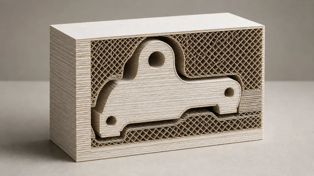
Sheet lamination 3d printing is an additive manufacturing family in which sheets are bonded layer by layer to form an object, with laminated object manufacturing, or LOM, as the best-known teaching example. In standards-based secondary descriptions of ISO/ASTM 52900:2021, the category covers bonded-sheet methods rather than a single machine design. [2]
This article moves from classic LOM to the broader sheet lamination AM family, then to ultrasonic additive manufacturing, or UAM, and composite-based additive manufacturing, or CBAM. It also keeps metric classes separate, so layer thickness, machine positioning, stated accuracy, throughput, and independently measured strength are not treated as equivalent. The current terminology standard behind that taxonomy, ISO/ASTM 52900:2021, is Edition 2, published in November 2021, 28 pages, status Published, and stage 90.93 (Confirmed). [1]
What Is Sheet Lamination Additive Manufacturing?
Sheet lamination additive manufacturing is the AM category in which sheets of material are bonded layer by layer to form an object, typically through stacking and cutting. In standards-aligned descriptions, it sits alongside the other major AM process families rather than describing one specific machine architecture. [2]
The umbrella term is broader than the casual phrase “laminated 3D printing,” and broader than LOM itself. LOM is a specific historical branch within the family, most often taught through paper-based examples, while other branches use different sheet materials and different bonding physics. [2] [11]
In the seven-category AM taxonomy, sheet lamination appears alongside binder jetting, directed energy deposition, material extrusion, material jetting, powder bed fusion, and vat photopolymerization. That framing appears both in a 2026 review that explicitly references ISO/ASTM 52900:2021 and in older ASTM-based secondary material, which is why sheet lamination is treated as a recognized process category rather than an informal label. [2] [3]
The core actions are simple in outline:
- Place or feed a sheet.
- Bond the sheet to the previous layer.
- Cut, mill, or otherwise form the layer boundary.
- Repeat until the stack is complete.
- Remove waste and finish the part.
Sheet Lamination vs LOM vs UAM vs CBAM
The simplest way to avoid confusion is to treat sheet lamination as the umbrella term, then LOM, UAM, and CBAM as distinct branches within or clearly aligned to that family. UAM is described in manufacturer documentation as a subset of sheet lamination using metal foils and an ultrasonically activated tool, while CBAM is described in academic work as a sheet-lamination-based composite process. [13] [9]
| Term | What it refers to |
|---|---|
| Sheet lamination | The broader AM category built from bonded sheets. [2] |
| LOM | The classic laminated object manufacturing branch, most often presented through paper-based examples. [11] |
| UAM | A metal-foil branch using an ultrasonically activated tool; typically a hybrid additive-subtractive route. [13] [7] |
| CBAM | A sheet-lamination-based composite route combining fiber sheets with thermoplastics. [9] [8] |
Historical Background: From Early LOM to Today’s Niche Variants
A key early milestone is the Feygin laminations patent, US4752352A, titled Apparatus and method for forming an integral object from laminations. Google Patents shows a filing date of 1987-04-17 and a publication date of 1988-06-21. Those dates place bonded-sheet object building firmly in the late-1980s formative period of additive manufacturing. [6]
Commercialization followed soon after. A U.S. WTEC chronology reports Helisys under laminated object technology with shipment in 1991, which makes it a useful anchor for the first commercial visibility of LOM. That paper-lamination route became the standard teaching example because it is easy to understand visually: bond a sheet, cut the contour, cross-hatch the waste, and remove the surrounding block later. Over time, the family expanded beyond paper toward metal-foil and composite-sheet variants, so modern discussion of sheet lamination usually centers on narrower industrial niches rather than one dominant paper process. [5] [11] [13] [9]
Technical Principles — Bonding Sheets Into a 3D Part
Like other AM methods, sheet lamination starts with a 3D shape divided into layers. The difference is that each layer is represented by a sheet or sheet region rather than by a filament road, droplet field, or powder slice. The build grows by stacking flat stock, bonding interfaces, and defining boundaries until the final geometry emerges from the laminated block. [4]
Across the family, both the bonding method and the shaping method matter. ORNL lists adhesives, ultrasonic welding, brazing, and thermal bonding as sheet-lamination bonding families, while CNC milling, laser cutting, vinyl cutting, and aqua blasting appear as forming methods. That is why sheet lamination should not be reduced to “paper glued together.” [4]
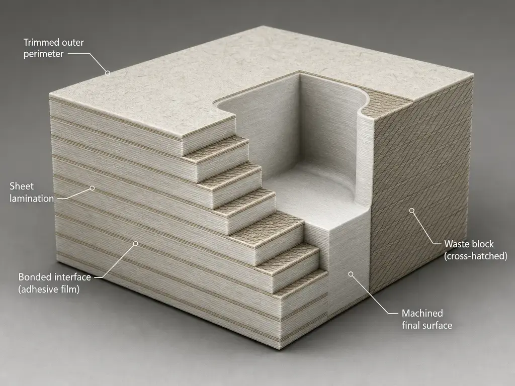
ORNL also distinguishes two broad workflow routes: cut-then-stack and stack-then-cut. In cut-then-stack systems, sheets are formed before stacking, which can save material but restrict what each slice can look like. In stack-then-cut systems, sheets are bonded into a block before being cut, which expands geometric freedom but increases material usage and later waste removal. That trade-off is one reason sheet lamination is best understood as an interface-joining and boundary-forming family, not as a uniform “print” behavior. [4]
How the LOM Process Works
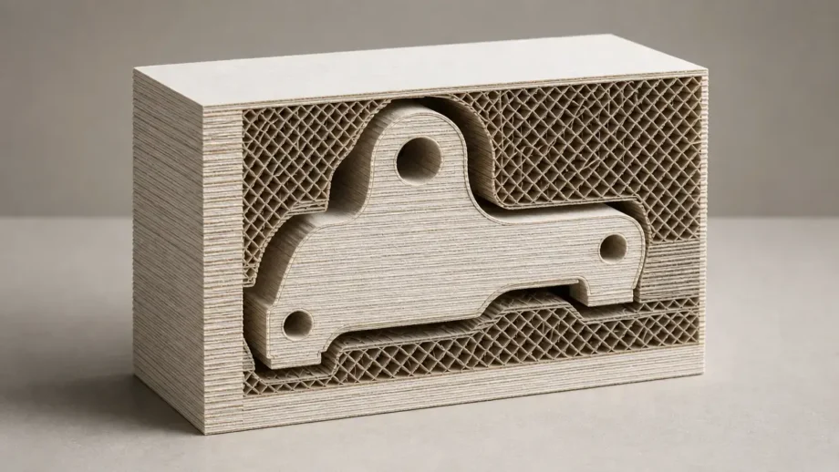
In classic LOM, the sequence is explicit: bond a fresh layer, contour-cut the part geometry, cross-hatch the surrounding waste, repeat that cycle until the build is complete, and then remove the remaining block around the part. In LOM literature, that waste-removal stage is often called decubing. The process is best understood as a bond-and-cut workflow, not a melt-fusion process. [11] [19]
TWI’s description also helps explain the feel of paper-based LOM parts in practice. It notes that paper-built parts can have wood-like characteristics, may need sanding to finish, and are often sealed to reduce moisture uptake. For historical context, a later paper-lamination system listing for the Mcor IRIS HD reports a build size of 256 × 169 × 150 mm for A4 paper, layer thicknesses of 0.1 mm or 0.19 mm, and office-paper examples such as 80 gsm A4 and 20 lb US Letter. Those numbers are best read as a historical system example from the paper-lamination branch, not as universal LOM values. [11] [18]
Types of Sheet Lamination Additive Manufacturing
Sheet lamination branches mainly by feedstock form and bonding physics. Classic LOM shows the paper route, UAM the metal-foil route, and CBAM the composite-sheet route. That diversity is why the family is better described as related processes than as one uniform technology. [11] [13] [9]
| Process | Bonding/forming method | Typical materials | Best fit / main limit |
|---|---|---|---|
| Classic LOM | Adhesive bonding plus contour cutting, cross-hatching, and later waste removal. [11] | Paper sheets and related laminates. [11] | Useful for visual prototypes and scale models; limited by waste handling, layer-thickness constraints, and internal-access issues. [11] [4] |
| Plastic sheet lamination | Thermal or adhesive lamination with cutting or milling. [4] | Polymer sheets and related sheet stock. [4] | Useful when sheet supply, bonding, and cutting are compatible; limited by geometry and bond quality. [4] |
| UAM | Solid-state ultrasonic foil bonding, usually combined with CNC machining. [13] [7] | Metal foils. [13] | Fits hybrid metal parts, embedded elements, and dissimilar-material builds; not a melt-bonding route. [7] |
| CBAM | Selective wetting or binder deposition, polymer powder deposition, stacking, consolidation, and removal of unbound material. [8] [9] | Fiber sheets with thermoplastic powder. [8] [9] | Fits structural thermoplastic composites; limited by process complexity and consolidation dependence. [8] |
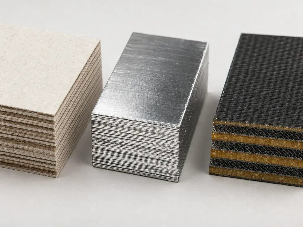
Do not confuse sheet lamination with material extrusion processes such as FDM or FFF, with vat photopolymerization methods such as SLA, MSLA, or DLP, with powder-bed processes such as SLS or MJF, or with binder jetting. All are layer-based, but they use different feedstock forms and bonding mechanisms. [2] [4]
Sheet Lamination 3D Printing Materials
When people ask about sheet lamination 3d printing materials, the starting point is feedstock form. The material arrives as a sheet, tape, foil, mat, or closely related sheet-format stock, then the process bonds and shapes it into a part. That can mean paper in classic LOM, polymer sheets in plastic variants, metal foils in UAM, or fiber sheets paired with thermoplastic powder in CBAM-class systems. At a high level, even ceramic or green-tape concepts appear in the literature, but only when the bonding and later processing route actually support them. [4] [11] [13] [5]
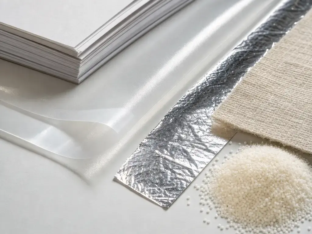
The practical boundary is stricter than “a sheet exists.” Printable feedstocks depend on sheet form plus compatible bonding, compatible forming or cutting, and consolidation or post-processing, not any sheet material in the abstract. ORNL’s process-family summary makes that clear because it spans adhesive, thermal, brazed, and ultrasonically bonded routes rather than one universal feedstock model. In UAM, that compatibility is especially material-dependent: an official design guide says the foils are usually 0.001–0.010 in thick, with the most common foils in the 0.005–0.006 in range, while independent review literature stresses that interface heating, preheat, and final outcomes remain process- and material-dependent. In CBAM, the material system differs again: fiber sheets are selectively wetted or binder-patterned, polymer powder is deposited, the sheets are stacked and heated to polymer melting temperature, and unbound material is removed afterward. [4] [13] [7] [8]
Performance Metrics — Accuracy, Layer Thickness, Speed, and Strength
Sheet lamination metrics are easy to misuse. Layer thickness is not the same as dimensional accuracy, dpi is not the same as feature size, and machine-axis positioning is not the same as final part tolerance. The only reliable comparison keeps the metric class, scope, and source class visible. [4] [10] [16]
| Metric | What it measures | Example figure in this article | Source class |
|---|---|---|---|
| Layer thickness | The sheet or layer height used during building. | LOM example: 0.002–0.020 in, or about 0.0508–0.508 mm. [12] | Secondary process library |
| Axis positioning and repeatability | Machine motion capability, not final part accuracy. | SonicLayer 1200 positioning ±0.0002 in; repeatability 0.0001 in. [14] | Manufacturer datasheet |
| Throughput | Claimed production rate. | UAM claim: 15–30 in³/h. [15] | Manufacturer web page |
| Resolution and stated accuracy | Patterning density and stated deviation, which are not identical. | CBAM 25: 1200 × 1200 dpi; 0.005 in / 125 µm print accuracy; 400 µm typical accuracy. [16] | Manufacturer spec sheet |
| Independent measured outcomes | Tested material behavior under stated study conditions. | CBAM Carbon/PEEK: tensile strength 206.4 MPa; flexural modulus 13.54 GPa; flexural strength 205.64 MPa. [10] | Independent scientific study |
A useful example of layer-thickness, process-example, secondary-source data is the LOM value above: 0.002–0.020 in, converted to about 0.0508–0.508 mm. That range is not a standard and not a current market spec; it is an illustrative process-library number. Even so, it shows an important constraint noted by ORNL: sheet thickness sets the lower bound on layer height for a given sheet-lamination setup. [12] [4]
For machine-axis metrics, manufacturer scope, Fabrisonic’s SonicLayer 1200 datasheet lists a 10 × 10 × 10 in work envelope, positioning of ±0.0002 in, repeatability of 0.0001 in, ultrasonic power of 2 kW, welding force of 650 lb, maximum welding speed of 120 ipm, and a 7500 rpm spindle. Those are machine and subsystem figures, not direct statements of finished-part accuracy. A separate manufacturer webpage gives a throughput, manufacturer-claim figure of 15–30 in³/h. UAM itself should still be described carefully: independent review literature defines it as a solid-state process, usually operating far below melting temperature, around 0.3–0.5 Tm, but also emphasizes that interface heating, preheat temperature, and final bonding outcomes remain process- and material-dependent. [14] [15] [7]
For CBAM machine and process figures, manufacturer scope, a CBAM 25 spec sheet lists an 18 × 17.7 × 4 in build volume, or 457 × 449 × 101 mm, a production speed of 11,000 cm³/h and 25 ft/min, 50–60 µm layer thickness, 50–70 µm powder size, 1200 × 1200 dpi print resolution, 0.005 in or 125 µm print accuracy, and 400 µm typical accuracy, with up to 125 µm achievable with reprint. Here, “print resolution” is a patterning-density claim, not a direct feature-size guarantee. A separate manufacturer material datasheet for CBAM Carbon Fiber PEEK lists material-property, manufacturer-data values of 140 MPa tensile strength, 12.74 GPa tensile modulus, 176.7 MPa ultimate flexural strength, 12.4 GPa flex modulus, HDT above 300 °C, and density of 1.40 g/cm³, but the same sheet explicitly says those values should not be used to establish design, quality-control, or specification limits. By contrast, an independent peer-reviewed study reports measured-part, independent-test results for CBAM-fabricated Carbon/PEEK of 206.4 MPa tensile strength, 13.54 GPa flexural modulus, 205.64 MPa flexural strength, and degradation onset around 350 °C, compared with about 298 °C for Carbon/Nylon 12 under that study’s conditions. [16] [17] [10]
Across the family, strength is bond-driven. ORNL notes that bond strength depends on lamination technique, and the UAM and CBAM literature both reinforce that point by tying outcome quality to interface condition, process parameters, and anisotropy. In practice, the most useful question is usually not “How strong is the raw material?” but “How well did this lamination route create and preserve the needed interlayer bond?” [4] [7] [10]
Applications
-
LOM: Conceptual prototypes, scale models, and other visual or educational parts remain the clearest fit for classic paper-based LOM, especially because the process is inexpensive, fast, and naturally produces a removable surrounding block during the build. [11]
-
UAM: Hybrid metal parts, embedded sensors or electronics, and dissimilar-material structures are the best-supported examples for UAM. Independent review literature describes UAM as a hybrid process that combines ultrasonic foil welding, CNC machining, and element embedding, while manufacturer material uses similar examples for context. [7] [15]
-
CBAM/composite sheet lamination: Structural thermoplastic composite parts are the natural application class for CBAM-style systems because the process starts from reinforcement sheets plus polymer powder, then consolidates the stack into a composite laminate. [8] [9]
These applications fit the family because sheet thickness, waste removal, support strategy, and bond quality all shape what is practical. The process is most attractive when sheet-format feedstock, deliberate post-processing, or solid-state bonding are advantages rather than burdens. [4]
Advantages and Disadvantages of Sheet Lamination 3D Printing
The advantages are real, but they are branch-specific. Classic LOM can produce large visual models and prototypes without powder handling. UAM offers solid-state metal bonding at temperatures much lower than melt-based metal AM, which helps explain its usefulness for dissimilar materials and embedded features. CBAM extends the family into long-fiber thermoplastic composite structures. At the family level, ORNL also notes that sheet lamination can enable large-scale parts and may avoid separate support structures. [4] [7] [8]
The disadvantages are just as important. ORNL flags layer-height limits from sheet thickness, time-consuming or wasteful material removal, and bond dependence on the lamination technique. In classic LOM, cross-hatched waste is part of the build logic, so post-build cleanup is not incidental. Internal voids and inaccessible trapped material can also be problematic, especially when the geometry fights the chosen workflow. TWI adds that paper-based LOM may have weaker surface quality or moisture sensitivity unless treated. [4] [11]
So the practical answer to “what are the advantages and disadvantages of sheet lamination 3d printing?” is that there is no single answer for the whole family. The right judgment depends on the branch, the sheet material, the bonding route, and the acceptable post-processing burden. [4]
Current Research and Market Context
Classic paper LOM is less prominent today mainly because its known constraints narrow where it fits best. Sheet-thickness limits, waste removal, and bond dependence all reduce its general-purpose appeal. Research and deployment continue more actively in branches that solve specialized problems. In UAM, the literature focuses on bond quality, defects at the bonding interface, plastic flow, preheat temperature, texture evolution, and heat-treatment effects. In CBAM-related work, the emphasis is on microstructure, porosity, consolidation quality, and independently measured composite performance rather than only vendor datasheets. [4] [7] [9] [10]
That makes qualification the central challenge. For both UAM and composite sheet-lamination routes, the key question is whether process settings can be tied to repeatable bond quality and predictable properties. No reliable market-share figure was found in the provided source set, so the safest conclusion is narrower: sheet lamination persists where data-backed process control justifies its niche advantages. [7] [10]
Conclusion: Where Sheet Lamination 3D Printing Fits Today
Sheet lamination 3d printing still matters, but as a selective set of process options rather than a default route for additive manufacturing. It remains one of the recognized AM categories, yet the family spans paper-based bond-and-cut methods, solid-state metal-foil bonding, and sheet-based composite consolidation. That range is exactly why broad claims about “sheet lamination performance” are usually misleading. The better question is not whether sheet lamination is good or bad in general, but which branch, bonding method, and post-processing route match the job. [2] [4]
FAQ
What is sheet lamination additive manufacturing?
Sheet lamination is an additive manufacturing category in which sheets of material are bonded layer by layer to form an object, usually with a later cutting, trimming, or shaping step. It is better treated as a process family than as one machine type, because paper, metal-foil, polymer-sheet, and composite-sheet variants do not all join material the same way. [2]
Is sheet lamination one of the seven additive manufacturing process categories?
Yes. In standards-aligned secondary descriptions of ISO/ASTM 52900:2021, sheet lamination is one of the seven main AM process categories. That classification keeps it distinct from binder jetting, material extrusion, powder bed fusion, and the other major families, even though all of them also build parts layer by layer. [2] [3]
How does the LOM process work?
Classic LOM follows a repeated sequence: bond a sheet, contour-cut the part geometry, cross-hatch the surrounding waste, repeat, and then remove the surrounding block after the build. That last cleanup step is often called decubing in LOM literature. The process is therefore part lamination and part controlled waste-management strategy. [11] [19]
What materials are used in sheet lamination 3d printing?
The family includes paper sheets, polymer sheets, metal foils, and fiber sheets paired with thermoplastic powders. The exact material set depends on the branch: classic LOM is associated with paper and similar laminates, UAM uses metal foil, and CBAM-class routes use reinforcement sheets plus polymer powder before consolidation. [4] [13] [8]
Is UAM a type of sheet lamination?
Yes. Fabrisonic’s design guide explicitly places ultrasonic additive manufacturing under sheet lamination. In that branch, metal foils are bonded with an ultrasonically activated sonotrode and the process is typically paired with CNC machining. Independent review literature supports the classification while also emphasizing that UAM is a solid-state metal process with parameter-dependent bonding behavior. [13] [7]
Expert: What does “solid-state” mean in UAM, and why is “cold welding” an oversimplification?
In UAM, “solid-state” means the build occurs without bulk melting of the work material. That matters, but it does not mean “no heat” or “no metallurgical complexity.” Independent review literature describes UAM as operating well below melting temperature while still involving friction, plastic deformation, temperature generation at the interface, and preheat effects that influence bonding quality and microstructure. [7]
Sources
- ISO — ISO/ASTM 52900:2021 status page
- Nature Portfolio (npj Advanced Manufacturing) — Additive manufacturing pathways for polymer-derived ceramics: processing, structure, and function
- NIST-hosted PDF — ASTM F2792 seven categories list (secondary confirmation)
- ORNL report — large-scale AM review with sheet lamination workflow, bonding, and limitations
- WTEC report — Rapid Prototyping in Europe and Japan chronology
- Google Patents — US4752352A, Apparatus and method for forming an integral object from laminations
- Springer (IJAMT) — A review of microstructure evolution during ultrasonic additive manufacturing
- ORNL MDF report — CBAM process steps in collaboration with Impossible Objects
- Utah State University DigitalCommons — Microstructural Characterization of Sheet Lamination-Based Additively Manufactured Fiber-Reinforced Thermoplastic Composites
- Springer — Mechanical and Thermal Characterization of Additively Manufactured Carbon/Nylon 12 and Carbon/PEEK Composites
- TWI — What is laminated object manufacturing (LOM)?
- CustomPartNet legacy — laminated object manufacturing process page
- Fabrisonic — UAM design guide
- Fabrisonic — SonicLayer 1200 datasheet
- Fabrisonic — UAM overview page
- Bentec mirror — CBAM 25 spec sheet
- Impossible Objects — CBAM material properties datasheet
- Advanced World Products — Mcor IRIS HD historical specs page
- University of Texas / conference PDF — Automated Fabrication of Monolithic and Ceramic Matrix Composites via Laminated Object Manufacturing (LOM)