
Summary
SLS vs MJF compares two polymer powder-bed processes used to produce complex parts without conventional support structures. Selective laser sintering (SLS) uses laser exposure to consolidate selected powder, while HP Multi Jet Fusion (MJF) uses selectively deposited agents and thermal energy. Both fit the powder bed fusion family, defined as additive manufacturing in which thermal energy selectively fuses regions of a powder bed. [1]
There is no universal winner. The relevant comparison is a specific machine-material-workflow combination: material grade, part size, orientation, surface requirement, inspection plan, powder handling, and post-processing route.
Where SLS and MJF sit in Powder Bed Fusion
Powder bed fusion (PBF) is the additive-manufacturing category in which thermal energy selectively fuses regions of a powder bed. [1] SLS and MJF can be compared at this functional level because both consolidate polymer powder within a bed, rather than extruding filament or curing liquid resin. That shared framing does not mean they use the same exposure method, process controls, or standardized subprocess label.
SLS is commonly described as laser-based polymer powder bed fusion, often shortened to LB-PBF/P in standards language. ISO/ASTM 52911-2 is specifically scoped to design guidance for laser-based powder bed fusion of polymers. [2] MJF is HP’s proprietary process name and should be treated as a polymer powder-bed technology, not relabeled as laser-based PBF or conventional adhesive binder jetting. The distinction matters when applying design guidance, machine documentation, and qualification evidence.
A brief, sourced timeline
Carl R. Deckard’s U.S. Patent 4,863,538, Method and Apparatus for Producing Parts by Selective Sintering, lists October 17, 1986 as its prior-art date and September 5, 1989 as its publication and grant date. [15] HP announced its Jet Fusion 4200 as a production-ready system and stated that deliveries would begin in late 2016. [14]
SLS vs MJF: what happens in one layer
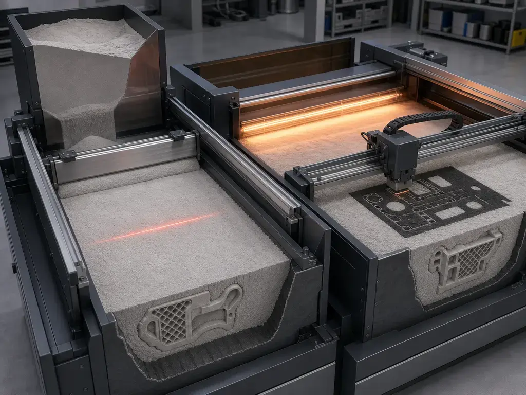
In SLS, a recoater spreads a powder layer across the build area and a laser scans the part cross-section. Thermal management keeps the powder bed within its process window as the machine repeats the spread-and-expose cycle. After the build, the powder bed cools before unpacking, depowdering, powder recovery, and any finishing or inspection steps. SLS is within the laser-based polymer PBF family addressed by ISO/ASTM 52911-2. [2]
In MJF, a fresh powder layer is spread and printheads deposit agents at selected locations. Infrared heating interacts with those agent-defined locations to produce fusion, then the machine advances to the next layer. Agent deposition plus infrared heating describes the core mechanism, not every thermal or machine-control detail used by every platform. Cooling, unpacking, depowdering, powder management, finishing, and inspection remain production steps rather than optional afterthoughts. [10]
MJF uses inkjet hardware, but it is not conventional adhesive binder jetting: thermal energy produces fusion in the polymer powder bed. Both processes fit the PBF family definition while using different methods to localize energy. [1]
One-layer sequence in SLS vs MJF
- Powder delivery: Each system spreads a fresh polymer powder layer.
- Part-location definition: SLS uses laser scanning; MJF uses selective agent deposition.
- Energy localization: SLS directs laser energy to selected regions; MJF controls the response to infrared heating through deposited agents.
- Fusion: The intended cross-section consolidates within the powder bed.
- Surrounding powder: Unfused powder supports the geometry during the build.
- Layer advance: The build area indexes for the next layer.
- Repetition: The cycle continues until the full geometry is formed.
- Post-build handling: Both routes require cooling, unpacking, depowdering, and finishing appropriate to the application.
Materials and taxonomy: SLS nylon vs MJF nylon is not one material
PA12 is a common comparison point, but SLS nylon vs MJF nylon is not a controlled material comparison unless the full material system is aligned. At minimum, compare the exact grade, machine model, layer setting or print mode, powder history, orientation, conditioning, test standard, specimen geometry, and as-built or post-processed state. Material portfolios are platform-specific and can change over time. Appearance is also platform- and material-dependent: EOS lists PA 2200 powder as white, while HP positions the Jet Fusion 5420W for white-part production. [11] [12]
| Criterion | SLS (laser PBF polymers) | HP MJF | What must be checked |
|---|---|---|---|
| Energy definition | Laser exposure | Agents + IR heating | Machine model and parameter set or print mode |
| Common comparison material | PA12 | PA12 | Exact grade, conditioning, refresh ratio |
| Ecosystem/material breadth | Multiple OEMs and qualified powders | HP-qualified portfolio | Current material datasheets for the platform being quoted |
| As-built color | Often white/natural for some PA12, including EOS PA 2200 | Platform/material dependent; white exists on 5420W | As-built color, finishing route, batch consistency |
Surface finish: as-built texture vs finishing routes
Surface finish has visual, tactile, and metrological aspects. A part can appear visually uniform while feeling granular, and a roughness parameter such as Ra describes a measured profile rather than every visible surface feature. The measured face matters: top, bottom, and vertical build-direction surfaces can differ. Many additive-manufacturing papers cite ISO 4287 and ISO 4288, while ISO 21920-2 defines current profile-texture parameters and ISO 21920-3 covers profile specification operators. [5] [6]
Rosso et al. compared as-built ISO 527 specimens made by SLS on an EOS FORMIGA P110 using EOS PA2200 Performance and by MJF on an HP Jet Fusion 4200 using HP 3D High Reusability PA12. Both used 100 µm layers; reported powder refresh ratios were 1:1 virgin-to-reused for SLS and 1:4 for MJF. Specimen orientation and conditioning were not specified, and no post-processing was reported. Using a Talysurf i-Series under ISO 4287/4288, with a 12.5 mm evaluation length and 2.5 mm sampling length, the study measured top-face Ra of 10.4 ± 1.6 µm for SLS and 8.7 ± 0.9 µm for MJF; bottom-face values of 15.0 ± 2.3 µm and 13.3 ± 1.0 µm; and build-direction values of 10.8 ± 0.8 µm and 11.2 ± 1.2 µm, respectively. [7] These face-specific results do not support a universal claim that either process is smoother.
Blasting can remove loose powder and alter tactile feel; dyeing changes appearance; vapor smoothing and coatings can affect surface sealing; machining can establish selected functional dimensions. Each finishing route can also change edges, dimensions, and inspection requirements.
Support-free does not mean post-processing-free. Powder-bed support reduces the need for conventional supports, but it does not eliminate depowdering, finishing, or verification.
Mechanical properties: what people mean by stronger
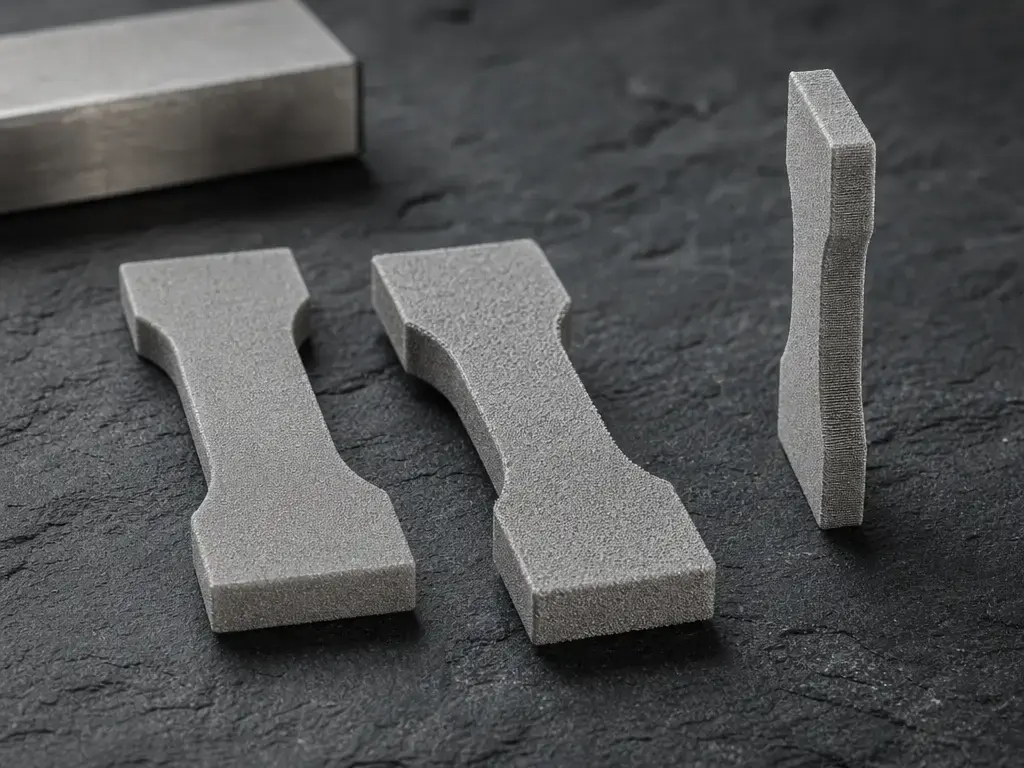
“Stronger” can refer to different responses. Tensile strength is the stress reached in a tensile test; modulus describes stiffness in the elastic region; strain at break indicates deformation before fracture. Toughness concerns energy absorbed before failure, while fatigue concerns repeated loading. These properties are related but not interchangeable, and a headline value is not meaningful without its material, orientation, conditioning, specimen, and test-method context.
EOS reports dry ISO 527-1/-2 results for PA 2200 of 48 MPa tensile strength in X, 48 MPa in Y, and 42 MPa in Z. The same datasheet reports strain at break of 18% in X, 18% in Y, and 4% in Z. The datasheet identifies axis and test standard, but machine model, layer setting, powder history, conditioning procedure, specimen subtype, and post-processing state are not specified in the cited table. [8]
Rosso et al. described MJF specimens as stiffer and SLS specimens as showing a tougher response under their specific comparison conditions: EOS FORMIGA P110 with EOS PA2200 Performance versus HP Jet Fusion 4200 with HP 3D High Reusability PA12, 100 µm layers, and reported powder refresh ratios of 1:1 and 1:4, respectively. Orientation, conditioning, specimen standard, and post-processing state were not specified in that comparison capsule. [7] This is a study-specific finding, not a general PA12 ranking.
Never compare PA12 datasheets without checking test standard, orientation, conditioning, and process parameter set. ISO 291 provides standard atmospheres for conditioning and testing plastics, including the commonly used 23 °C and 50% relative-humidity comparative atmosphere. [4]
Dimensional accuracy and repeatability: measured error vs supplier tolerance
Accuracy is closeness to a nominal or reference dimension. Precision and repeatability describe consistency among measurements, while resolution is the smallest addressable process increment. Neither resolution nor layer thickness is a finished-part tolerance. A dimensional result must identify the artefact, datums, measurement method, sampling plan, orientation, and post-processing state.
Rosso et al. reported measured size error using an OGP SmartScope Flash 200 coordinate measuring machine. For ISO 527 specimens made on the EOS FORMIGA P110 with EOS PA2200 Performance and the HP Jet Fusion 4200 with HP 3D High Reusability PA12, both at 100 µm layers and reported powder refresh ratios of 1:1 and 1:4, mean size error was 0.034 ± 0.035 mm for SLS and 0.319 ± 0.079 mm for MJF. For ASTM E606 specimens under the same reported machine, material, layer, and powder-history conditions, values were 0.052 ± 0.030 mm for SLS and −0.053 ± 0.069 mm for MJF. Build orientation, conditioning, and post-processing state were not specified. [7]
These are geometry-specific study measurements, not supplier tolerance promises. They do not establish flatness, warpage, hole accuracy, mating-feature capability, build-to-build repeatability, or production-batch capability. ISO/ASTM 52902 defines test artefacts for quantitatively assessing geometric performance of additive-manufacturing systems; it is not a universal tolerance guarantee. [3]
| Requirement you care about | What to request in quotes / samples | Why process labels are not enough |
|---|---|---|
| “Tight fit” mating features | Nominal dimensions, datums, metrology method, sampling plan, post-process state | Geometry, orientation, and finishing can change error |
| Repeatability across batches | Lot traceability, powder-reuse policy, acceptance tests | Powder history and conditioning can affect results |
| Flatness/warpage risk | Orientation plan, cooling protocol, inspection criteria | Thermal history and nesting affect distortion |
Porosity, density, and watertightness: linked but not interchangeable
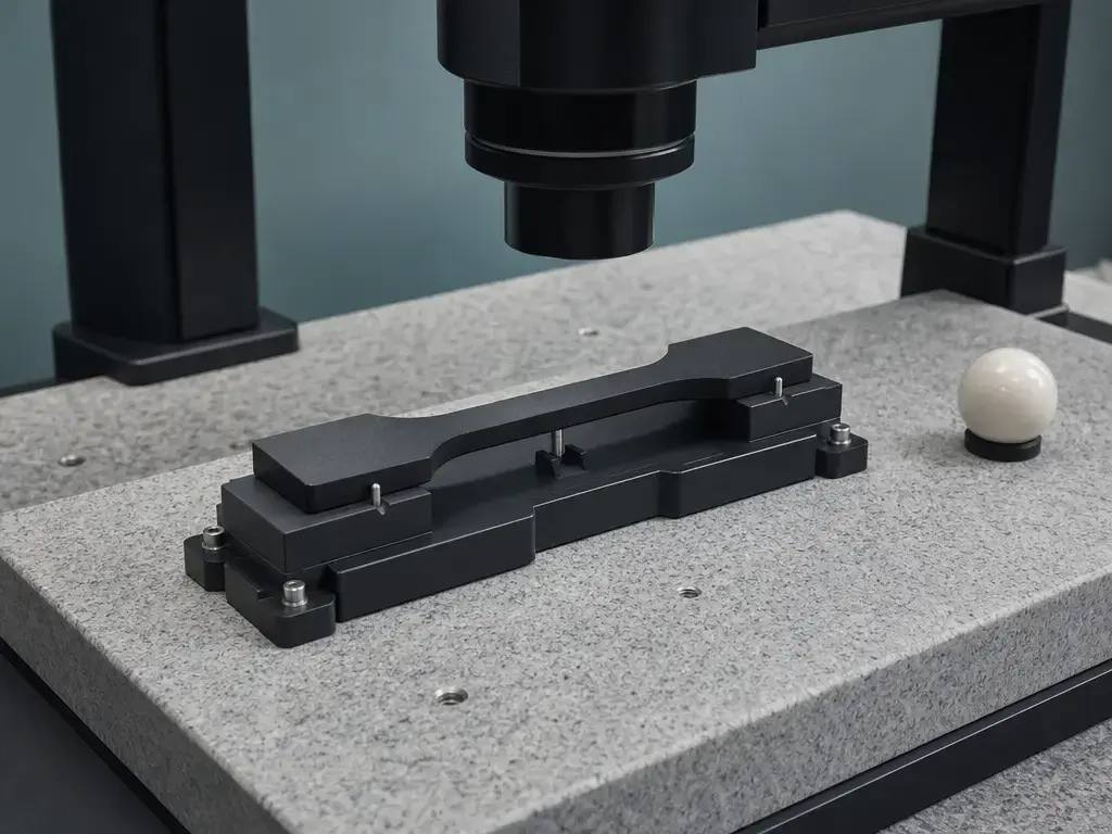
Porosity is the volume fraction occupied by voids. Total porosity includes all void space; open porosity is connected to the exterior surface; closed porosity is enclosed within the material. Density-based methods can estimate void content, but they do not independently establish pore connectivity, size, location, or leak paths.
Rosso et al. evaluated density through helium pycnometry plus mass-and-volume calculations for PA12 specimens from the EOS FORMIGA P110/EOS PA2200 Performance SLS system and the HP Jet Fusion 4200/HP 3D High Reusability PA12 MJF system. At 100 µm layers and reported refresh ratios of 1:1 for SLS and 1:4 for MJF, total porosity was 7.95 ± 0.09% for SLS and 6.75 ± 0.18% for MJF; open porosity was 6.35 ± 0.01% and 5.62 ± 0.06%; closed porosity was 1.61 ± 0.10% and 1.13 ± 0.24%. Orientation, conditioning, specimen format, and post-processing state were not specified. [7] These values do not prove watertightness, leak resistance, chemical resistance, or suitability for pressurized service. Where sealing matters, test representative finished parts with an application-relevant leak method.
Production workflow and throughput: define the denominator before saying faster
“Faster” can mean exposure time, complete build-cycle time, usable parts per build, or total lead time to accepted parts. The final measure includes cooling, unpacking, depowdering, powder recovery, finishing, inspection, rework, and yield. A shorter exposure stage does not necessarily mean a shorter time to qualified parts.
For comparable quotes, request packing assumptions, cooling time, powder-refresh practice, labor and equipment for depowdering and finishing, inspection requirements, expected yield, and delivery assumptions. HP’s manufacturing-aids paper includes vendor-defined material-system and powder-reuse claims, but these depend on stated test and operating assumptions rather than establishing a universal MJF outcome. [13] Distinguish a vendor’s powder-reusability claim from a refresh ratio and from a service bureau’s actual powder-management practice.
Applications: SLS vs MJF for functional parts
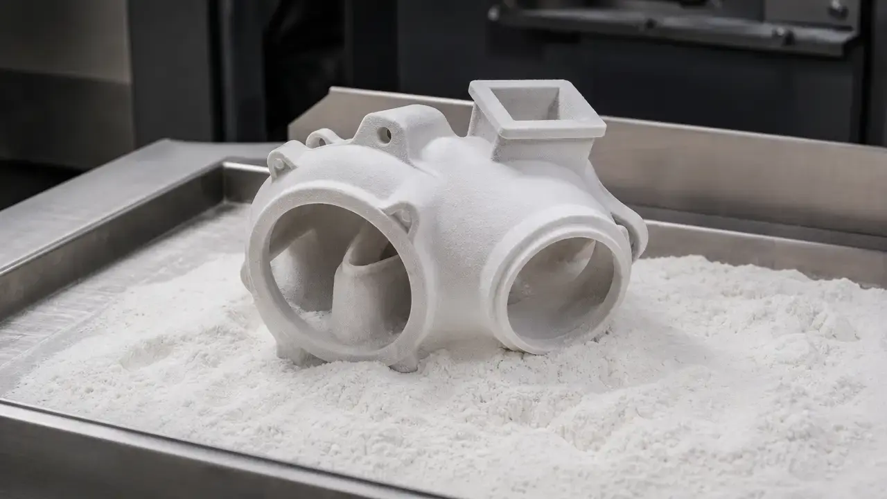
SLS and MJF can both be considered for housings, brackets, ducts, jigs, and fixtures when polymer powder-bed geometry fits the job. Surrounding powder can support complex shapes during the build, but enclosed channels, cavities, and manifolds still require an intentional route for powder evacuation and cleaning.
For snap features, request strain evidence for the specified material, orientation, conditioning state, and finished condition. For hot fixtures, use the relevant thermal-property value from the exact material-system datasheet and test method rather than a generic PA12 description. For internal manifolds, define powder-removal access and use representative leak testing when sealing is functional. Conditioning should also be specified: ISO 291 defines standard atmospheres for plastics testing, including the commonly used 23 °C/50% relative-humidity atmosphere. [4]
Specify these seven requirements before requesting SLS or MJF quotes.
- Exact material grade and approved material designation.
- Machine model and print mode or layer setting.
- Build orientation and critical loading axes.
- Conditioning method and test environment.
- As-built and finished surface requirements.
- Critical dimensions, datums, tolerances, and inspection method.
- Powder removal, sealing needs, and functional validation requirements.
Limitations and failure modes
Both processes can leave trapped powder in enclosed volumes, so cavities and channels need evacuation paths and cleaning verification. Thermal history can contribute to distortion; build orientation and rotation can affect polymer powder-bed results. [17] Surface texture can vary between top, bottom, and build-direction faces under the same reported build conditions. [7] Moisture conditioning can affect plastics testing, making controlled conditioning important. [4] Finishing introduces further variation because it can change dimensions, edges, texture, appearance, and sealing behavior. Representative samples and defined inspection criteria are part of the engineering decision, not optional extras.
Research and market context
Rosso et al. provide a useful comparison framework because the study assessed porosity, as-built roughness, dimensional size error, and mechanical behavior for stated SLS and MJF PA12 systems. Its value lies in the documented material-system context: EOS FORMIGA P110 with EOS PA2200 Performance versus HP Jet Fusion 4200 with HP 3D High Reusability PA12, both at 100 µm layers and with reported refresh ratios of 1:1 and 1:4. [7]
Lupone et al. compared SLS and MJF using the same glass-bead-reinforced PA12 powder rather than neat PA12. In the reported ZX orientation, MJF showed strength values up to approximately 40% higher across the study’s load scenarios; machine model, layer setting, powder history, conditioning, specimen standard, and post-processing state are not specified here. [16] Platform size can also affect procurement: EOS lists the P 770 build volume as 700 × 380 × 580 mm, while HP lists an effective Jet Fusion 4200 build volume of 380 × 284 × 380 mm. These are machine-volume specifications, not part-performance data. [9] [10]
Selection guide: SLS vs MJF which is better?
There is no blanket answer to SLS vs MJF. Choose SLS when the required material qualification is available on a specific laser-PBF platform, the part envelope fits the selected system, and the workflow is validated for the required geometry and inspection criteria. An EOS P 770, for example, has a manufacturer-listed build volume of 700 × 380 × 580 mm, which can matter where part size or nesting capacity is a primary constraint. [9]
Choose MJF when an appropriate HP-qualified material, validated finish, representative coupon evidence, and production workflow meet the part requirements. Appearance should be treated as platform-specific: HP positions the Jet Fusion 5420W for white-part production, not all MJF platforms or materials. [12] In either route, procure against like-for-like evidence:
- Exact grade.
- Machine and layer setting or print mode.
- Powder history.
- Orientation.
- Conditioning.
- Test standard and specimen.
- As-built or post-processed state.
- Inspection plan.
FAQ
This is general engineering guidance. Current supplier datasheets, application-specific sample builds, agreed conditioning, and inspection results take precedence over broad process comparisons.
Is SLS vs MJF mainly a difference in material or printing process?
It is primarily a difference in printing process. SLS uses laser exposure, while MJF uses selectively deposited agents with infrared heating. Both can be considered polymer powder-bed thermal-fusion processes under the PBF family definition. [1] Material remains equally important because a label such as PA12 does not identify the exact grade, powder history, machine settings, orientation, or finishing state.
SLS vs MJF which is better for functional parts?
Neither is automatically better. Functional-part selection should start with loading direction, material grade, surface condition, dimensional requirements, finishing route, powder-removal access, and validation evidence for the actual geometry. A bracket, duct, housing, jig, or snap feature can emphasize different risks. The useful question is whether the supplier can demonstrate conformity to the stated requirements with representative builds.
What are the main SLS nylon vs MJF nylon differences?
The differences can include the qualified material portfolio, energy-localization method, powder-management practice, appearance options, and machine-specific processing window. Similar PA12 labels do not prove equivalent behavior. Compare the exact grade, machine and print mode, powder history, orientation, conditioning, test method, specimen geometry, and post-processing state. Vendor claims should be interpreted within their stated assumptions. [13]
Is SLS vs MJF surface finish noticeably different as-built?
It can be, but the difference is face-specific rather than universal. Rosso et al. measured different as-built roughness outcomes on top, bottom, and build-direction faces for specified SLS and MJF PA12 systems. [7] Part orientation, geometry, powder condition, and finishing can alter visual appearance and tactile feel. Evaluate representative surfaces in their intended orientation and finished condition.
Is MJF faster than SLS?
Not necessarily. “Faster” might mean exposure time, full build-cycle time, usable parts per build, or total lead time to inspected and accepted parts. Cooling, unpacking, depowdering, finishing, inspection, and yield can dominate the result. Vendor material-system and powder-management claims also depend on defined assumptions. [13] Compare complete production scenarios using the same part mix and acceptance criteria.
What should I compare in a powder bed fusion comparison before I choose?
Compare the exact material grade; machine and parameter set; powder history; orientation; conditioning; test standard and specimen geometry; as-built and post-processed surfaces; and inspection plan. Conditioning should be controlled because plastics testing depends on the stated atmosphere and treatment. [4] Also define critical dimensions, powder-removal routes, sealing or leak requirements, batch sampling, and the evidence required to accept production parts.
Sources
- ISO/ASTM 52900:2021 Additive manufacturing — General principles — Fundamentals and vocabulary, ISO, 2021.
- ISO/ASTM 52911-2:2019 Additive manufacturing — Design — Part 2: Laser-based powder bed fusion of polymers, ISO, 2019.
- ISO/ASTM 52902:2023 Additive manufacturing — Test artefacts — Geometric capability assessment, ISO, 2023.
- ISO 291:2008 Plastics — Standard atmospheres for conditioning and testing, ISO, 2008.
- ISO 21920-2:2021 Geometrical product specifications — Surface texture: Profile — Part 2, ISO, 2021.
- ISO 21920-3:2021 Geometrical product specifications — Surface texture: Profile — Part 3, ISO, 2021.
- In-depth comparison of polyamide 12 parts manufactured by Multi Jet Fusion and Selective Laser Sintering, Rosso et al., Additive Manufacturing, 2020.
- EOS PA 2200 Material Data Sheet, EOS.
- EOS P 770 Polymer 3D Printer, EOS, accessed October 16, 2026.
- HP Jet Fusion 4200 3D Printing Solution Brochure, HP.
- EOS PA 2200 Process and Material Data Sheet, EOS.
- HP Jet Fusion 5420W 3D Printer, HP.
- Producing Manufacturing Aids with HP Multi Jet Fusion 3D Printing, HP, May 2018.
- HP Delivers World’s First Production-Ready 3D Printing System, HP, 2016.
- US4863538A — Method and Apparatus for Producing Parts by Selective Sintering, Carl R. Deckard, 1989.
- Selective Laser Sintering versus Multi Jet Fusion: A Comprehensive Comparison Study Based on PA12/GB, Lupone et al., 2024.
- Build Orientation Effects in Polymer Powder-Bed Fusion, Calignano, Giuffrida, and Galati, Journal of Manufacturing Processes 65, 2021.