
Summary
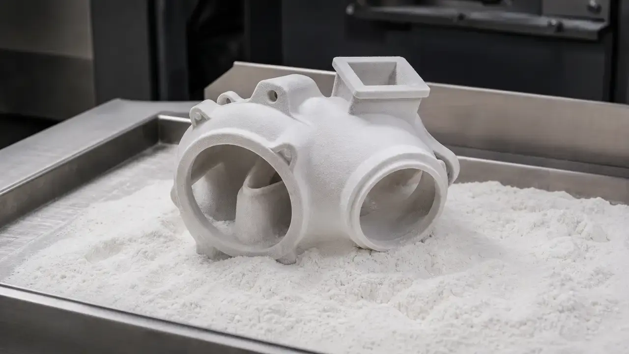
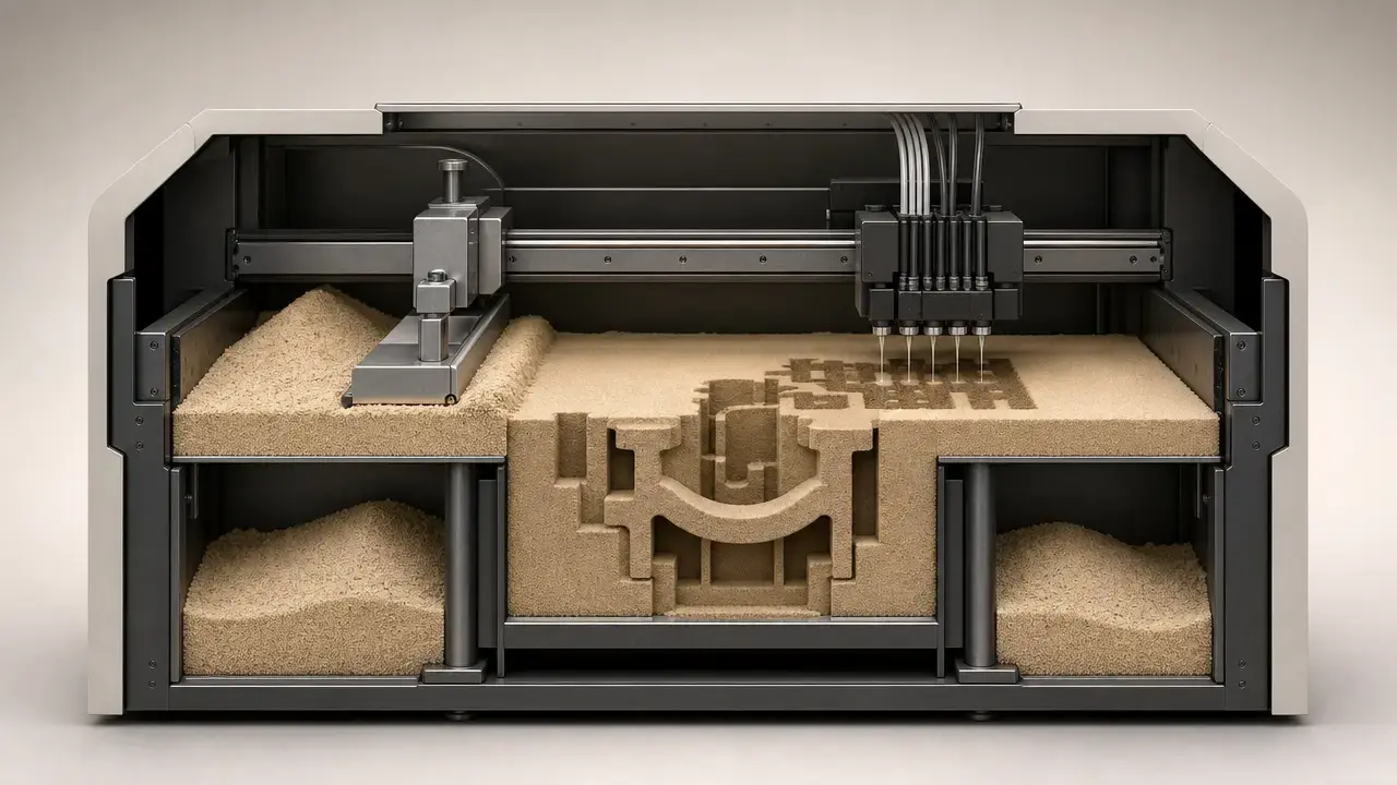
Sand 3D printing, in the narrow industrial sense, means binder jetting of expendable sand molds and sand cores for later metal casting, not post-processing of plastic prints. ISO/ASTM 52900:2021 defines binder jetting as an additive manufacturing process in which a liquid bonding agent is selectively deposited to join powder materials, and NIST describes it more plainly as fusing powdered material together with a binder. [3] [4] [5]
The main trade-off is simple: printed sand tooling can remove the need for a physical pattern or core box, which helps when geometry changes quickly or internal passages are difficult to tool conventionally, but the process still has to be qualified for a specific sand, binder, machine, orientation, and casting workflow. [1] [2] [6] Printed sand tooling is typically sacrificial, meaning it is shaken out or decored after pouring rather than kept as a permanent tool. [6] Other additive routes can support casting-related work, but this article stays focused on binder jetting because it is the main industrial route for direct sand molds and cores. [4] [5] [15]
From Sand Casting Tooling to Digital Molds
Conventional sand casting usually starts with a pattern and, when internal passages are needed, a core box. [7] The foundry uses those tools to form mold cavities and cores, assembles the mold, pours metal, and then breaks the sand away afterward. [7] That workflow is mature, but tooling can become a bottleneck when designs keep changing, when tool storage and maintenance matter, or when a program needs several rounds of iteration before the geometry stabilizes. [7]
Direct printed molds and cores fit into that same foundry workflow as a patternless tooling alternative, not a universal replacement for conventional routes. [15] [16] Foundry-focused review literature consistently describes binder-jetted sand molds and cores as especially useful for rapid casting, complex internal features, and short or changing design cycles. [15] [16]
What Is Sand 3D Printing?
Sand 3D printing is the additive manufacture of expendable sand molds and sand cores that will later be used for foundry casting. [4] [5] In practice, the dominant industrial route is binder jetting: a liquid binder is selectively deposited into a powder bed of sand, layer by layer, until the mold or core is formed. [4] This article follows ISO/ASTM 52900:2021 as its terminology authority and focuses on binder jetting because independent review literature treats it as the main industrial route for direct printed sand molds and cores. [3] [4] [15]
| Is | Is not |
|---|---|
| Expendable sand molds/cores for metal casting | Sanding 3D prints |
| Tooling for casting | Direct metal printing |
| Binder jetting of sand | Material jetting of build material |
A sand mold defines the external cavity for the casting, while a core is the separate insert that creates internal cavities or features the pattern cannot form directly. [7] AFS defines a core as “a sand or metal insert in a mold to shape the interior of the casting or that part of the casting that cannot be shaped by the pattern.” [7] That distinction matters because sand core 3D printing often creates the most practical value: complex internal passages, undercuts, and consolidated core packages can be made directly from CAD without a dedicated core box for every feature. [7] [15] [16]
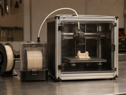
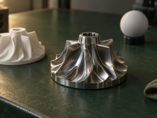
This topic is not the same as direct metal AM, and it is not the same as material jetting. [4] ISO/ASTM 52900 defines material jetting separately as a process in which droplets of feedstock material are selectively deposited, which is a different process family from binder jetting of a sand powder bed. [4] In this article, “sand 3D printing” means printed sand tooling for later casting. [4] [15]
How Binder Jetting Sand Works (Step-by-Step)
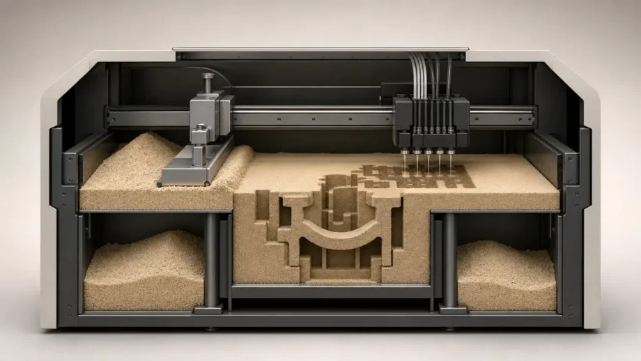
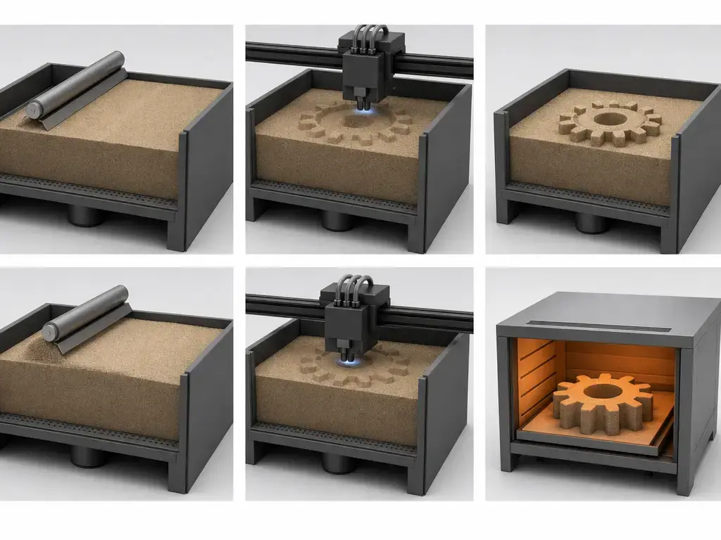
Binder jetting sand is a powder-bed process. [4] A thin layer of sand is spread across the build area, the printhead selectively deposits binder where the next cross-section should solidify, and the machine repeats that cycle until the mold or core is complete. [4] [5] NIST’s plain-language description is useful here because it captures the mechanism cleanly: binder jetting prints three-dimensional structures by fusing powdered material together with a binder. [5]
After the binder is deposited, the printed body is not yet a ready-to-pour foundry tool. [6] Fraunhofer IGCV describes a drying or curing phase after binder application so the bonded sand gains the structural integrity needed for handling, and places that step inside a broader process chain from CAD data through printing to casting break-out. [6] Loose, unbound sand supports the geometry during printing, including enclosed cavities and internal passages that would be difficult to create with rigid tooling. [5] [6] In this workflow, “as-printed handling strength” is a safer term than assuming one universal meaning of “green strength,” because the relevant question is whether the bonded sand body can survive extraction, cleaning, assembly, and movement before later process steps. [6] [15]
Depowdering and cleaning come next, followed by optional coating or wash steps, mold or core assembly, pouring, and then shakeout or decoring after solidification. [6] [15] The exact bottlenecks and risks depend on binder chemistry, sand media, recoating conditions, geometry, and foundry practice, so universal numbers are misleading. [1] [15]
Typical process steps
- CAD + gating/rigging design + optional casting simulation
- Slicing + job-box nesting
- Sand recoating
- Binder deposition
- Curing / drying / hardening
- Depowdering + cleaning
- Optional coating/wash
- Mold/core assembly
- Metal pouring
- Shakeout, decoring, inspection
These steps vary by binder system and foundry practice. [6] [15]
Sand Molds, Sand Cores, and the Casting Workflow (Minimum Needed Foundry Context)
A sand mold defines the outer shape of the casting. [7] In common foundry practice, the mold is often organized as cope and drag halves around a cavity, and it can include gating, feeders or risers, and vents to guide metal flow, feed solidification shrinkage, and let gases escape. [7] A core is the insert that forms internal cavities or passages the mold alone cannot produce. [7]
Printed cores are often the most compelling use of the technology because they can consolidate multiple pieces into one geometry, reduce assembly steps, and make internal passages easier to realize. [15] [16] Review literature on binder-jetted sand molds and rapid sand casting repeatedly points to complex internal geometry as a main reason to use direct printed cores: a single printed core can replace a multi-piece core package or avoid a separate core box for each internal feature. [15] [16] The result is still expendable tooling consumed by the casting process, not a permanent insert. [7] [15]
Where printed sand can replace or supplement conventional tooling
- one-off prototypes
- spare parts
- complex internal channels
- consolidated core packages
- design validation pre-hard-tooling
- bridge production
- low-volume casting
Material Systems: Sands and Binder Families (Why “Sand” Isn’t One Material)
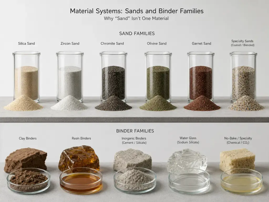
“Sand” in binder jetting is not a single material family. [13] [14] Feedstocks can include silica or quartz sands, synthetic or ceramic foundry media, and higher-performance materials such as sintered bauxite. [8] [14] Those choices matter because thermal expansion, flowability, permeability, refractoriness, and surface behavior depend on grain morphology and mineralogy, not just on printer settings. [1] [14] In Bobrowski et al., one quartz-sand example is ExOne FS001 with an average grain size of 0.13–0.14 mm, a uniformity ratio of 89%, and AFS number 97. [13]
Binder families vary as well. [15] Furan systems are common in the sand binder-jetting literature, phenolic systems are used on some platforms, and inorganic, silicate, or geopolymer directions are being explored in part because of emissions and operating objectives. [8] [15] [18] [19] None of those families is universally better, because the trade-offs include handling strength, cure behavior, collapsibility, gas evolution, surface response, and fit with the rest of the foundry process chain. [15] [18] [19]
| System type | Typical role | Article caution | Source anchor |
|---|---|---|---|
| Furan + silica/quartz sands | Common mold/core route | Formulation + curing + emissions vary; don’t generalize strengths | [13] [15] |
| Phenolic systems (binder-jet sand) | Used on some platforms | Don’t infer from furan data | [8] [15] |
| Inorganic / silicate / geopolymer direction | Emissions-reduction driver | Qualification + collapsibility + process details are application-specific | [18] [19] |
| Ceramic / bauxite / synthetic sands | Tune thermal & gas transport | Cost/handling/wear tradeoffs may apply; method-specific results | [14] |
Performance Metrics (and How to Test Them Without Fooling Yourself)
Printer specifications often mention layer height, resolution, and dimensional accuracy, but those figures describe the printed sand tooling itself, not the final metal casting. [8] For one manufacturer-stated example, ExOne’s S-Max Pro page lists a job box of 1,800 × 1,000 × 700 mm, a build volume of 1,260 L, a layer height of 0.2–0.5 mm, and dimensional accuracy of ±0.5 mm and ±0.1% over 500 mm. [8] Printer accuracy describes sand tooling; final casting accuracy depends on coating, assembly, shrinkage allowance, and solidification effects. [7] [8] ISO/ASTM 52919:2025 is also important here because it is a test-method standard for AM-made metal casting sand moulds, not a universal pass/fail tolerance for cast parts. [1]
Strength is even more method-sensitive. [1] Bobrowski et al. tested cylindrical specimens of Ø50 × 50 mm made on FS001 quartz sand with furfuryl resin FB001 and hardener FA001, and the paper reports splitting tensile strength while also calculating a derived tensile value from the correlation ( Rm = 0.65 Rp ). [13] By contrast, the bauxite study reports 3-point bending per BDG P72 on 22.4 × 22.4 × 172 mm specimens, using a 20 kN load cell, a 150 mm support distance, and ( n = 5 ) specimens per parameter set. [14] Room-temperature handling data, later-cure strength, and hot behavior during pouring are not interchangeable, and neither are splitting tensile and flexural results. [1] [14] Only compare like-for-like tests, with like-for-like specimen geometry, material system, and cure history. [1] [13] [14]
Permeability is another metric that is easy to misuse. [7] AFS defines permeability as the property of a mold material to allow passage of mold or core gases during the pouring of molten metal. [7] In the bauxite study, gas permeability was measured per BDG P41 and AFS 5224-13-S on cylindrical samples 50 mm in diameter and 50 mm high, so the resulting numbers belong to that method and specimen geometry. [14] Under those study conditions, printed CastBall bauxite averaged 315 in permeability while GS14 averaged 224. [14] Thermal behavior is similarly method-bound: ISO/ASTM 52919:2025 explicitly includes thermal expansion among the test methods relevant to AM-made sand moulds. [1] [2]
Surface roughness follows the same rule. [14] A rougher printed mold does not automatically imply the same roughness on the metal casting, because coating, wetting, metal flow, and solidification all intervene. [14] In the bauxite paper, printed CastBall samples showed mean roughness depth ( R_z ) of about 170 µm, while the resulting casting roughness was on the order of 110 µm in that study. [14] That is useful as a method-scoped example, not as a universal promise about casting finish. [14]
Variables that change results
| Variable | What it shifts |
|---|---|
| Sand PSD | Strength, permeability, roughness |
| Binder family | Strength, emissions, collapse behavior |
| Binder amount / saturation | Strength, dimensional drift, gas defects risk |
| Catalyst % | Cure behavior, handling strength |
| Layer height | Resolution, print time, stair-stepping |
| Recoating speed | Defect risk, throughput |
| Humidity | Cure consistency, handling strength |
| Curing time | As-printed handling strength, downstream stability |
| Orientation | Strength anisotropy, sampling result, permeability path |
| Coating | Surface finish, gas transport, casting quality |
| Handling damage | Dimensional error, local weakness |
Metrics not to mix up
- Layer height vs dimensional accuracy
- Mold/core strength vs casting strength
- Permeability vs metal porosity
- Mold roughness vs casting roughness
- Cure time vs print time
- Single-study specimens vs qualified production capability
Are 3D Printed Sand Casting Molds Strong Enough for Casting?
Often yes, if the mold or core is designed and qualified for the alloy, pour temperature, geometry, handling route, coating system, and safety factor involved. [1] [15] But “strong enough” is not one universal property, because the sand body has to survive handling, assembly, gas loading, erosion risk, and pouring conditions within a specific process window. [1] [15]
The numbers only make sense when they stay attached to their method. [1] In Bobrowski et al., Ø50 × 50 mm cylindrical specimens made in a quartz sand plus furfuryl resin system gave a 3D-printed solid core splitting tensile strength of 2.39 MPa and a derived tensile value of 1.55 MPa, while the 3D-printed shell core gave 1.23 MPa splitting tensile and 0.80 MPa derived tensile. [13] In the bauxite paper, 22.4 × 22.4 × 172 mm specimens made with a no-bake binder system and stored at ambient conditions for over 24 h before characterization reached an average 3-point bending strength of 2.3 MPa at 200 mm/s with medium binder content, and about 2.5 MPa when binder was increased by one-third. [14] The same paper also states that, with suitable process parameters, 3-point bending strength above 3 MPa and permeability above 300 could be achieved. [14] Different specimen shapes and standards change the number. [1] [14] Do not compare splitting tensile values to 3-point bending values as if they were the same strength measure. [1] [13] [14]
Sand 3D Printing vs Traditional Sand Casting Tooling (Decision Framework)
Traditional sand casting tooling relies on patterns and core boxes that are amortized over repeated runs. [7] That makes sense when geometry is stable and volume is high enough to justify design, manufacture, storage, maintenance, and change control of the tooling. [7] In foundry terms, the pattern or core box is a capital tool, while the printed route replaces much of that hard tooling with a digital file plus machine time and process qualification. [7] [15]
The practical decision usually comes down to production volume, design change rate, geometry complexity, qualification burden, and program risk. [15] [16] Independent reviews describe binder-jetted sand molds and cores as especially well suited to low-volume, complex, or high-iteration work, while conventional routes remain strong for stable, proven geometries. [15] [16] In many programs, the most rational answer is hybrid: print the difficult core, keep the simpler outer mold conventional, or validate a new casting with printed tooling before investing in hard tooling. [15] [16]
| Criterion | Sand 3D printing | Traditional sand molds/cores | Best-fit note |
|---|---|---|---|
| Tooling | Direct from CAD | Pattern/core-box dependent | Printed wins for iteration |
| Geometry | Strong for complex cores, consolidated packages | Strong for stable proven geometries | Hybrid often best |
| Unit volume economics | Strong for low-volume/high-mix | Often best for high volume | Avoid universal cost claim |
| Qualification | Needs material/process validation | Established routes | Depends on application risk |
Limitations, Safety, and Qualification Risks
The main mechanical and dimensional limitations are straightforward. [15] Printed sand features can crack during depowdering, thin sections can be vulnerable to handling damage, and tolerance assumptions can fail once coating, assembly, and pouring are added to the chain. [13] [15] Layerwise fabrication can also introduce stair-stepping and orientation effects, while the usable process window can shift when the sand media or binder family changes. [1] [15]
Safety and environmental claims also have to stay conditional. [18] In a 2025 pilot-scale study, inorganic binder systems showed reductions of over 90% in BTEX and over 94% in PAHs relative to organic systems in that study context. [18] The 2024-12 Foundries BREF document adds process context on binder-system choices, including low free-formaldehyde warm-box options and notes on inorganic geopolymer collapsibility. [19] Those are not blanket claims about every foundry or every sand-printing line. [18] [19] Consult the binder SDS and your internal EHS review path as part of normal program development. [18] [19]
Qualification is better treated as a test plan than as a slogan. [1] [2] ISO/ASTM 52919:2025 — Additive manufacturing — Qualification principles — Test methods for metal casting sand moulds — provides a framework that includes standard practice for sampling specimens, tensile testing, bending or transverse testing, gas permeability testing, thermal expansion testing, documentation, purchasing guidance, verification of AM machine performance, and an annex on specimen identifier and orientation index. [1] [2] That structure is useful because it forces the right questions: which material system was used, in which orientation, with what cure history, sampled how, and tested by which method. [1] [2] No reliable universal tolerance, strength, price, or lead-time figure exists for all sand 3D printing. [1]

Research and Industrial Adoption (Independent, Non-Vendor Framing)
Independent review literature continues to focus on alternative sands, gas transport, binder migration, process monitoring, and the relationship between process parameters and casting outcomes. [15] [16] That is where many of the practical open questions still sit: not whether sand printing exists, but which sand, binder, cure path, and test regime give repeatable results for a specific foundry job. [15] [16]
Industrial scale is already visible, but examples should stay clearly labeled as manufacturer-stated or press-release-stated rather than treated as a complete market map. [8] [10] [11] [12] ExOne’s S-Max Pro product page lists a 1,800 × 1,000 × 700 mm job box, 1,260 L build volume, 0.2–0.5 mm layer height, dimensional accuracy of ±0.5 mm and ±0.1% over 500 mm, and binder systems including furan and phenolic. [8] ExOne’s S-Max Pro datasheet additionally reports vendor-reported build rate up to 145 L/h, LOI of 1.0–2.1%, and reclaim of 30%, which are vendor metrics rather than standard qualification criteria. [9] voxeljet’s VX4000 data sheet lists a 4,000 × 2,000 × 1,000 mm build space, 200 dpi x/y print resolution, and an available sand process example using furan. [12] At the smaller end, ExOne’s S-Print datasheet lists an 800 × 500 × 400 mm build box, 0.26–0.38 mm layer height, and binder systems including furan, CHP, HHP, and inorganic. [10] ExOne’s June 22, 2026 S-Print Pro press release states a 1,200 × 750 × 500 mm build volume, 0.10–1.00 mm layer thickness with 0.28 mm standard, footprint under 12 m², 400 dpi printhead, and deliveries beginning in the second half of 2026. [11] Trade-press overviews can help explain printer and binder categories, but they are better used as context than as a substitute for standards, data sheets, and method-scoped test results. [17]
Key Takeaways for Sand 3D Printing in Practice
Sand 3D printing is best understood as binder jetting of expendable sand molds and cores for later metal casting: a patternless tooling route that can be effective for complex geometry, fast iteration, and core consolidation, but only when the material system and downstream foundry process are qualified together. [1] [4] [15] ISO/ASTM 52919:2025 is a useful test-method anchor, not a casting-performance guarantee, and machine specs should be read as tooling specs for a cited machine example, not as promises about every casting outcome. [1] [8] [14] Tooling specs do not equal guaranteed casting tolerance or casting finish. [7] [8] [14]
FAQ
What is sand 3D printing?
Sand 3D printing means making expendable sand molds and cores by additive manufacturing, usually binder jetting, for later metal casting. [4] [5] The printed sand object is usually tooling rather than the final product, and it is typically shaken out or decored after pouring. [6] It does not mean sanding plastic prints, and it is not the same process family as direct metal AM. [4] [7]
How does binder jetting sand work for molds and cores?
A recoater spreads thin layers of sand, and a printhead selectively deposits liquid binder where the next cross-section should solidify. [4] [5] After printing, the bonded sand body goes through drying or curing, then depowdering, cleaning, optional coating, assembly, and finally pouring. [6] Loose surrounding sand supports enclosed geometry during the build, which is one reason the process can make complex cores and passages without conventional hard tooling. [5] [6]
Are 3D printed sand casting molds strong enough for casting?
Often yes, but only in a process-specific sense. [1] [15] One study on Ø50 × 50 mm cylindrical specimens in a quartz sand and furfuryl resin system reported 2.39 MPa splitting tensile and 1.55 MPa derived tensile for a solid printed core, while a shell core in the same study reported 1.23 MPa and 0.80 MPa. [13] Another study on 22.4 × 22.4 × 172 mm prismatic specimens reported 3-point bending values around 2.3–2.5 MPa under specific conditions. [14] Those numbers are not directly interchangeable. [1] [13] [14]
What is a sand core in sand core 3D printing for casting?
A core is the insert that shapes internal cavities or other regions the pattern cannot make directly. [7] In sand core 3D printing, that insert is printed from CAD rather than produced in a dedicated core box. [7] [15] That can reduce assembly steps, consolidate multi-piece core packages, and make complex internal passages easier to realize, but the printed core is still expendable tooling used for a later casting step. [15] [16]
How accurate is sand 3D printing—and what changes after pouring metal?
Accuracy claims on printer pages apply to the sand tooling, not automatically to the finished casting. [8] For example, ExOne’s S-Max Pro page lists a layer height of 0.2–0.5 mm and dimensional accuracy of ±0.5 mm and ±0.1% over 500 mm for that machine example. [8] After pouring, coating, assembly, shrinkage allowance, and solidification all influence the metal dimensions and surface condition. [7] [8]
Expert: How does ISO/ASTM 52919:2025 help you test and compare AM-made sand molds?
It provides a structured test-method framework rather than a vague instruction to “qualify the process.” [1] The ISO catalog entry identifies test methods including tensile strength, transverse strength, gas permeability, and thermal expansion, while the preview contents page shows supporting sections for sampling specimens, documentation, purchasing, machine-performance verification, and a specimen identifier/orientation annex. [1] [2] That helps teams compare like with like, but it is not a casting-quality guarantee and not a printer acceptance standard for every use case. [1]
Expert: How should you interpret permeability numbers across different sand/binder systems and test setups?
Carefully, and only within matched methods when possible. [1] [14] Permeability is the mold material’s ability to let mold or core gases pass during pouring, but the reported value depends on specimen geometry and the test standard used. [7] In the bauxite study, permeability was measured per BDG P41 and AFS 5224-13-S on cylinders 50 mm in diameter and 50 mm high, with average values of 315 for CastBall and 224 for GS14 under that study setup. [14] That does not make 315 a universal “better” number outside the same method context. [1] [14]
Sources
- ISO. ISO/ASTM 52919:2025 — Additive manufacturing — Qualification principles — Test methods for metal casting sand moulds. Catalog page, Edition 1, 2025-09.
- ISO/ASTM preview via iTeh. ISO/ASTM 52919:2025 preview PDF. First edition preview, 2025-09.
- ISO. ISO/ASTM 52900:2021 — Additive manufacturing — General principles — Fundamentals and vocabulary. Catalog page, Edition 2, 2021-11, confirmed 2025.
- ISO/ASTM preview via iTeh. ISO/ASTM 52900:2021 preview PDF. Preview PDF, 2021.
- NIST. Binder Jetting. Official technology overview.
- Fraunhofer IGCV. 3D Sand Printing—Sandbased Additive Manufacturing. Workflow and process-chain overview.
- American Foundry Society. Metalcasting Terms. Foundry glossary for core, permeability, and related terms.
- ExOne. S-Max Pro Sand 3D Printer | Foundry Molds. Product page accessed 2026-08-31.
- ExOne. S-Max Pro datasheet PDF. PDF, 2022-04.
- ExOne. S-Print datasheet PDF. PDF, 2020-06.
- ExOne. New S-Print Pro: Affordable Industrial Sand 3D Printing. Press release, 2026-06-22.
- voxeljet. VX4000 machine data sheet PDF. Machine data sheet, validity 01/2021.
- Bobrowski et al., Materials. 3D Printed (Binder Jetting) Furan Molding and Core Sands—Thermal Deformation, Mechanical and Technological Properties. 2023.
- Major et al. Use of Sintered Bauxite Sand in Binder Jetting of Casting Cores. International Journal of Metalcasting, 2026.
- Sivarupan et al., Additive Manufacturing. A review on the progress and challenges of binder jet 3D printing of sand moulds for advanced casting. 2021.
- Upadhyay et al., Journal of Manufacturing Processes. 3D Printing for Rapid Sand Casting—A Review. 2017.
- Foundry Management & Technology. Understanding 3D Sand Printers and Binder Technologies. 2019.
- Garitaonandia et al., Molecules. Assessment of Harmful Emissions from Multiple Binder Systems in Pilot-Scale Sand Casting. 2025.
- European Commission JRC. Foundries BREF first draft. 2024-12 PDF.