
Summary: what a PTS file is
In this article, a PTS file means the point-cloud .pts format: a plain-text/ASCII exchange file for 3D points, not a mesh, surface model, or CAD solid. [1] [11]
In practice, PTS is best treated as a widely used convention rather than a single rigid specification. One documented convention uses a first-line point count followed by seven values per point, but importer behavior, column order, and attribute handling vary by software. Autodesk ReCap also describes raw .pts as an unstructured point cloud, which is one reason PTS usually carries less scan context and metadata than E57. [1] [4] [14]
| What it contains | What it usually lacks | Common issues | Best next step |
|---|---|---|---|
| ASCII rows of XYZ and, in many workflows, optional intensity and RGB data. [1] [7] | A formal self-describing schema, rich scan structure, and E57-style metadata. [4] [11] [14] | Wrong column mapping, unit confusion, and color/intensity mismatches. [1] [7] | Inspect the text first, confirm units and CRS externally, then convert only if the target format adds structure you actually need. [4] [11] |
What’s inside a PTS point cloud file (and why the “schema” varies)
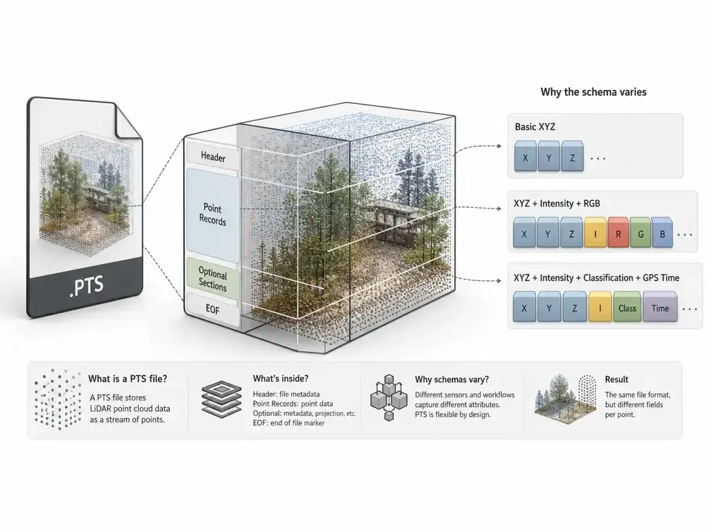
A common convention is simple: the first line stores a point count, and each following line stores one point. nanoCAD documents exactly that layout for one PTS convention, and CloudCompare’s command-line option -ADD_PTS_COUNT shows that some tools actively add the first-line count for compatibility when saving ASCII clouds. [1] [10]
After that header, the common layout is XYZ plus optional attributes, often intensity and RGB, but that layout is not mandatory. Leica Cyclone 3DR’s ASCII parser is deliberately flexible: it can decode X, Y, Z, I, R, G, and B from a set of numbers, ignore extra values, or accept files where some values are missing. That is why two valid PTS files can share the same extension yet still need different import mapping. [2] [7]
A tiny schematic example looks like this:
3
1.000 2.000 3.000 120 255 240 230
1.010 2.005 3.020 118 254 239 229
1.025 2.010 3.040 121 253 238 228
Schematic only — real exporters may omit or add columns, or use a different order. [7]
Intensity and color are separate attributes, and their numeric conventions are not universal. In nanoCAD’s documented PTS import behavior, RGB is expected as 0–255 per channel and imported intensity is normalized to 0–65535. In Leica Cyclone’s PTX export documentation, PTX intensity is 0–1, and the same KB note says Cyclone-exported PTS may use integer intensity values from -2048 to 2047. Those differences are why “PTS format” is better read as a common convention than as one fixed rule every tool follows. [1] [2]
Structured vs unstructured: what a PTS file usually does not preserve
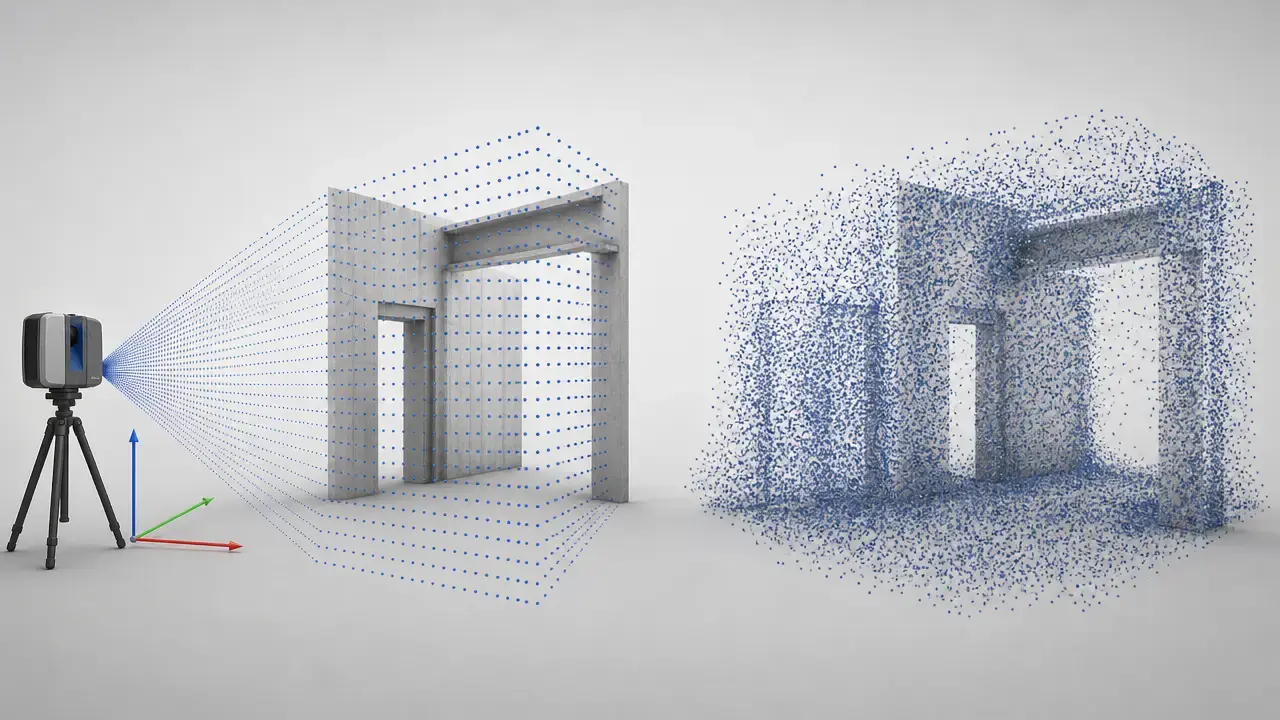
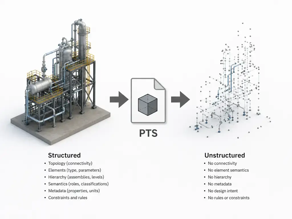
Autodesk ReCap explicitly describes raw .pts as an unstructured point cloud. In practice, that means the file may preserve the points themselves while losing the scan-origin information some downstream operations need, such as per-scan organization, scanner viewpoint, or the structure required for scan-aware segmentation and similar workflows. ReCap’s own structured E57 export note makes the contrast clear by calling out row/column information and registration transforms. [3] [4]
It also helps to separate coordinates from coordinate-system meaning. A PTS file can contain valid XYZ values and still leave important context outside the file, such as units, project CRS, datum, control strategy, or registration notes. The CAD Interop guide characterizes PTS/PTX as ASCII with no formal standard and notes that georeferencing is not natively encoded there, so survey reports, control files, and project documentation often matter as much as the point rows themselves. [5] [11]
Conversion cannot recreate scan structure or registration history that was never written into the handoff. If the export has already flattened structured scans into an unstructured PTS, later conversion can still preserve coordinates and perhaps mapped attributes, but it cannot reliably reconstruct missing scan origins, row/column ordering, or prior registration context. [3] [4]
PTS vs PTX vs E57 (plus XYZ and LAS/LAZ) — what to choose
For most real workflows, the question is really PTS vs E57 point cloud, plus one special case: PTX, when per-scan pose and scan-grid structure matter. The table below summarizes documented behavior from the cited vendor, project, and standards sources. [1] [2] [4] [11] [12] [13] [14]
| Format | Encoding | What it can carry well | Common tradeoffs |
|---|---|---|---|
| PTS | Plain-text ASCII rows. | Quick single-cloud exchange and manual inspection; optional XYZ, intensity, and RGB by convention. | No formal ASTM/ISO-style published standard was verified in the cited sources, and downstream tools often treat it as unstructured. |
| PTX | ASCII with per-scan headers. | Scan-based exports with rows, columns, scanner pose, and transforms. | Still bulky text, and documented meter/intensity conventions here are Cyclone export behavior rather than a universal rule. |
| E57 | Hybrid file with a small binary header, binary sections, and XML hierarchy. | Standardized exchange of point clouds, attributes such as color/intensity, and 2D images. | Less human-readable than raw ASCII and more complex than a flat text dump. |
| XYZ / LAS / LAZ | Simpler ASCII or compact binary survey-style targets, depending on the format. | Minimal coordinate exchange or more compact downstream delivery. | Usually less transparent than PTS text, and not a substitute for missing scan structure. |
PTS is the loosest option. One documented convention is a first-line count plus X Y Z intensity R G B, but no formal ASTM/ISO-style published standard for PTS was verified in the cited sources. [1] [11]
PTX is the structured ASCII branch most closely tied to terrestrial scan exports. Leica Cyclone’s PTX documentation describes per-scan sections with number of columns, number of rows, scanner registered position and axes, and a 4×4 transformation matrix. In that same Cyclone context, PTX coordinates are exported in meters, PTX intensity uses 0–1, and PTX can contain one or more scan clouds. [2]
E57 is different in kind. ASTM Committee E57 lists ASTM E2807 as the 3D imaging data-exchange specification, libE57Format describes E57 as storing point clouds plus associated attributes and 2D images, and Huber’s overview explains that the file architecture uses a 48-byte header, optional binary sections, and an XML hierarchy rather than plain ASCII point rows. [12] [13] [14]
So the choice is mostly about how much meaning must survive the handoff. Use PTS when readability and quick interchange are enough, PTX when scan pose and scan-grid context matter in an ASCII workflow, and structured E57 when you want a more standardized exchange container that can preserve richer context. LAS/LAZ and XYZ are better understood as workflow targets for specific downstream needs, not as direct replacements for structured scan history. [2] [3] [4] [11]
How to open PTS file data (viewer, CAD/BIM, and CLI)
Because PTS is text, the safest workflow starts with inspection, then moves to a viewer, CAD/BIM tool, or CLI pipeline once you know what the columns mean. [3] [5] [9]
Opening checklist
- Keep the untouched original PTS file and do your testing on a working copy. [4] [11]
- Inspect the first line and the per-row column count before import. [1] [10]
- Confirm units and CRS externally from project notes, control, or survey deliverables. [5] [11]
- Verify color and intensity mapping, not just XYZ. [1] [7]
- Check whether the cloud is already registered or unified, or whether scan-by-scan structure still matters. [2] [4]
- Only then save a working copy to E57, LAZ, RCP/RCS, or another downstream format your toolchain expects. [3] [6] [11]
Autodesk ReCap is a common CAD/BIM route because its help lists PTS as both an import and export format, and the same page notes structured E57 export with row/column information and registration transforms. Leica Cyclone 3DR lists .pts and .ptx in both point-cloud import and export support, alongside E57, LAS, and LAZ. FARO SCENE also lists PTS and PTX among its export formats, and CloudCompare’s FILE I/O table includes .pts among the ASCII point-cloud formats it can read and write. [3] [6] [8] [9]
For CLI and batch work, PDAL’s readers.pts reads Leica Cyclone PTS files and infers dimensions from text points. PDAL also documents default_srs and override_srs options, which helps when the file itself does not carry enough spatial-reference context. CloudCompare’s command-line option -ADD_PTS_COUNT is another practical clue that the first-line point count is a common compatibility feature, not a universal guarantee for every ASCII point-cloud file. [5] [10]
Conversion workflow: PTS to E57, LAS/LAZ, PLY, or XYZ (two cases)
Think about conversion in two cases: a single unified cloud, or a scan set where structured scan context still matters. That distinction matters more than the file extension alone. [3] [4]
Case A — converting a unified/unstructured PTS (single cloud)
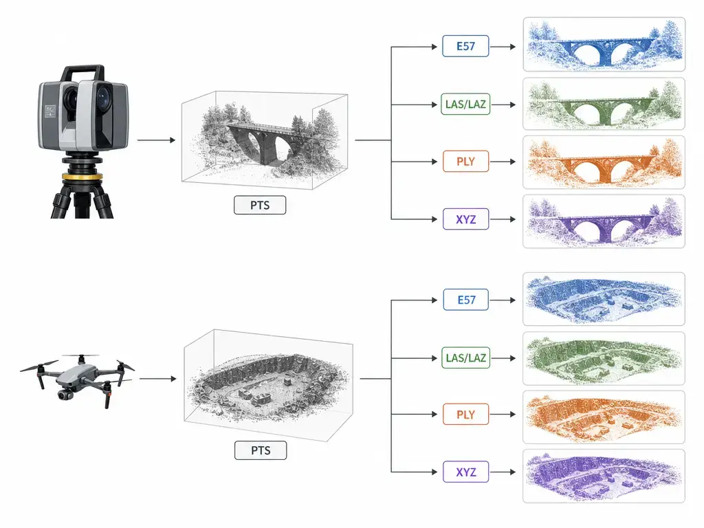
If the source is already one unified or unstructured cloud, conversion is mostly about preserving coordinates and whatever attributes you can map correctly. Structured E57 is usually the better archival or cross-platform exchange target, LAS/LAZ can be the more compact downstream choice for survey-style pipelines, XYZ is the bare-minimum ASCII path when only coordinates matter, and some point-cloud tools also offer PLY as another geometry-oriented export target. Before saving, validate units, point count, and whether intensity or RGB are actually present in the source columns instead of assumed by the importer. [3] [6] [9] [11]
Case B — converting scan sets where scan positions/structure matter
If scan positions, row/column ordering, or registration transforms matter, PTS may already be the wrong handoff. ReCap says raw .pts is unstructured, while Cyclone’s PTX documentation describes a per-scan header with rows, columns, scanner axes and position, and a 4×4 transform matrix. ReCap’s structured E57 export note points to the same distinction by calling out row/column information and registration transforms. In Cyclone’s own description, PTX is for gridded scan clouds rather than unordered unified clouds. Once those relationships are absent from the PTS export, later conversion cannot reconstruct them. [2] [3] [4]
Conversion risks to document
- Units may not be encoded or obvious, even when the coordinates themselves look correct. [1] [11]
- CRS or georeferencing may live outside the file, so sidecar metadata matters. [5] [11]
- Intensity scale may change between tools; nanoCAD documents normalization to 0–65535 on import, while Cyclone documents PTX intensity as 0–1 and notes a different integer convention for Cyclone-exported PTS. [1] [2]
- RGB may be dropped if the importer expects different columns; Cyclone 3DR’s ASCII reader accepts multiple column maps and both 0–255 and 0–1 RGB token styles. [7]
- Registration or scanner-pose metadata may be absent in PTS; ReCap’s unstructured
.ptswarning is the key limitation. [4] - Large ASCII files are slow and memory-heavy; one industry guide gives an illustrative size of about 1 GB for 10 million points and roughly 5–10× larger than E57 or LAZ, but that figure depends on precision, whitespace, and which attributes are written. [11]
Common problems when importing PTS (and quick fixes)
If the cloud imports at the wrong scale, suspect units first. The common PTS convention documented by nanoCAD describes point rows and attributes, but not a universal embedded unit system, and the CAD Interop guide warns that georeferencing is not natively encoded there. The quick fix is to verify a known distance or control point, then set units and spatial reference explicitly in the importer or pipeline instead of trusting defaults. PDAL’s SRS options are helpful precisely because that context may need to be supplied from outside the file. [1] [5] [11]
If color is missing or obviously wrong, suspect column mapping. Cyclone 3DR can decode RGB as integers from 0–255 or as floats from 0–1 depending on the format tokens, while nanoCAD documents a 0–255 RGB convention for its PTS import. If the importer guesses the wrong column order, color may disappear, shift channels, or be interpreted as something else entirely. The fix is to inspect the first rows and manually map the fields if the software allows it. [1] [7]
If intensity looks washed out or clipped, suspect range mismatch rather than bad geometry. nanoCAD normalizes imported intensity to 0–65535, Cyclone PTX uses 0–1, and the Cyclone KB notes a different integer convention for Cyclone-exported PTS. The same point values can therefore display very differently across viewers. If the file will not import or takes too long, remember that raw ASCII is bulky: the CAD Interop guide’s ~1 GB per 10 million points figure is illustrative, not universal, but it helps explain why very large PTS files are slower to parse than compact binary alternatives. [1] [2] [11]
Why PTS still appears in modern workflows (and when it’s reasonable)
PTS persists because it is transparent and still widely supported as an ASCII exchange format. PDAL has a dedicated readers.pts, CloudCompare reads and writes .pts as ASCII point-cloud data, Leica Cyclone 3DR lists .pts import and export support, and FARO SCENE lists PTS/PTX among its export formats. That makes PTS useful as a debugging, handoff, or “open it and inspect it” format even when it is not the best long-term archive. [5] [6] [8] [9]
The broader exchange and archival trend, however, points toward E57. ASTM Committee E57 lists E2807 as the data-exchange standard, libE57Format describes E57 as storing point clouds plus attributes and 2D images, and Huber’s overview explains the hybrid XML/binary design that is more self-describing and storage-efficient than flat ASCII. No reliable origin year for PTS was verified in the cited sources. [12] [13] [14]
When to use a PTS file — and when to convert it
Use a PTS file when the goal is quick inspection or simple interchange, the sender and receiver already agree on the column layout, and units or CRS are documented somewhere else in the project. That is the format’s comfort zone: temporary handoffs, troubleshooting, and single-cloud deliveries where readable text matters more than embedded structure. [1] [4] [5] [11]
Convert sooner when you need more structured, standardized, or compact behavior. Structured E57 is the safer choice when row/column information and registration transforms matter, PTX is still relevant when Cyclone-style scan pose must survive in an ASCII workflow, and LAS/LAZ may be the better downstream target when the receiving pipeline prefers compact survey-style data. The practical rule is simple: keep PTS for convenience, but do not expect it to preserve meaning that was never encoded in the first place. [2] [3] [6] [11] [12] [14]
FAQ
What is PTS point cloud file format?
PTS point cloud file format is a plain-text/ASCII way to store 3D points line by line. One documented convention uses a first-line point count followed by point rows containing XYZ, intensity, and RGB, but Cyclone 3DR’s ASCII documentation shows that real importers may accept missing, extra, or remapped columns. [1] [7]
How to open PTS file data?
The safest method is to inspect the text first, then load it in a point-cloud tool that understands ASCII mapping. ReCap lists PTS as import/export, PDAL provides readers.pts, and CloudCompare reads and writes .pts as an ASCII point-cloud format. [3] [5] [9]
PTS vs E57 point cloud: which should I use for exchange/archiving?
Use PTS when you mainly need a readable, quick-transfer text cloud. Use E57 when you need a more standardized exchange or archive format: Autodesk documents structured E57 export with row/column info and registration transforms, ASTM anchors E57 with E2807, and E57 documentation describes support for point data, attributes, and 2D images in a hybrid XML/binary file. [3] [12] [13] [14]
Why does my PTS import at the wrong scale?
Usually because units or spatial reference were assumed, not verified. The common PTS row convention does not solve scale or CRS by itself, and PDAL’s documented SRS options are a reminder that this context may need to be applied externally. Check a known distance, confirm project units, and confirm the intended coordinate system before converting again. [1] [5] [11]
Expert: Why do some tools treat PTS as “unstructured,” and what do I lose vs PTX/structured E57?
Because PTS is often just a flat point dump. ReCap explicitly calls raw .pts unstructured, while Cyclone’s PTX documentation describes per-scan rows, columns, scanner pose, and transforms, and ReCap’s structured E57 note calls out row/column information plus registration transforms. What you lose with flattened PTS is usually scan-origin context, scan-grid ordering, and some registration meaning. [2] [3] [4]
Expert: Why does intensity look wrong after conversion?
Because intensity conventions differ across tools. nanoCAD documents normalization to 0–65535 on import, Cyclone documents PTX intensity as 0–1, and the same Cyclone KB notes a different integer convention for Cyclone-exported PTS. If the viewer assumes the wrong range, the display can look clipped, flat, or inconsistent even when the coordinates are fine. [1] [2]
Sources
- nanoCAD point cloud data formats help —
https://nanocad.com/learning/online-help/nanocad-platform/point-clouds-data-formats/ - Leica Cyclone PTX File Format KB PDF —
https://nexus.hexagon.com/community/cfs-filesystemfile/__key/communityserver-discussions-components-files/735/PTX-File-Format.pdf?_=638615963512586589 - Autodesk ReCap supported file formats —
https://help.autodesk.com/view/RECAP/ENU/?contextId=supported_file_formats - Autodesk ReCap technical support: Unable to create geometry from segmented Point Clouds —
https://help.autodesk.com/view/RECAP/ENU/?caas=caas/sfdcarticles/sfdcarticles/Creating-geometry-from-segmented-Point-Clouds.html - PDAL
readers.ptsdocumentation —https://pdal.io/en/stable/stages/readers.pts.html - Leica Cyclone 3DR technical specifications —
https://rcdocs.leica-geosystems.com/docs/technical-specifications-cyclone-3dr-technical-specifications - Leica Cyclone 3DR Script SCloud ASCII parsing docs —
https://cyclone3dr.leica-geosystems.com/help/2025.0/Script/class_s_cloud.html - FARO SCENE export formats supported —
https://knowledge.faro.com/Software/FARO_SCENE/SCENE/Export_Formats_Supported_by_SCENE - CloudCompare FILE I/O wiki —
https://www.cloudcompare.org/doc/wiki/index.php/FILE_I/O - CloudCompare command line mode wiki —
https://cloudcompare.org/doc/wiki/index.php/Command_line_mode - CAD Interop PTS/PTX format guide —
https://www.cadinterop.com/en/formats/cloud-point/pts-ptx.html - ASTM Committee E57 fact sheet —
https://mcsdocs.astm.org/committee-documents/E57_Fact_Sheet_2019.pdf - libE57Format project documentation —
https://github.com/asmaloney/libE57Format - Daniel Huber, “The ASTM E57 File Format for 3D Imaging Data Exchange” —
https://publications.ri.cmu.edu/storage/publications/pub_files/2011/1/2011-huber-e57-v3.pdf