
Summary
Artec Ray II is a strong option when a project calls for stationary, long-range terrestrial laser scanning, but it is not automatically the best construction laser scanner for every job. Its advantages are clearest where fixed tripod setups, long sightlines, broad coverage, and disciplined scan-to-BIM or as-built documentation workflows matter most. [1] [4]
In construction, scanner performance is defined less by brochure numbers than by delivered accuracy, registration quality, control or georeferencing strategy, interoperability, and whether the final model or drawing meets project tolerance. Artec’s manufacturer-stated Ray II specifications are substantial: 360° horizontal and 300° vertical field of view, 0.5–130 m range, and 3D point accuracy of 1.9 mm at 10 m, 2.9 mm at 20 m, and 5.3 mm at 40 m, all stated at 68% confidence. The same manufacturer materials list 18 arcsec angular accuracy and 1.0 mm + 10 ppm range accuracy. Those figures describe device-level capability, not guaranteed building-scale deliverable accuracy after registration, control, and modeling. [1]
Decision Snapshot: Who Ray II Is For (and Who It Isn’t)
Use this six-part rubric before calling any scanner “best” for construction:
- Delivered accuracy & QA fit (30%).
- Range + coverage efficiency (20%).
- Registration & georeferencing workflow (15%).
- Environmental robustness & site practicality (15%).
- Interoperability & deliverables (15%).
- Downstream modeling burden (5%).
That framing matters because Ray II’s published performance is documented mainly through manufacturer and official product sources, while standards and NIST literature help interpret what those specs mean in practice. In the source set reviewed for this article, no reliable independent standardized Ray II field-validation study was found as of July 28, 2026. That does not make the scanner weak; it means the evaluation should separate manufacturer-stated device specs from project-level outcomes. TLS error sources vary with instrument, distance, geometry, and environmental conditions, so standards-based field checks still matter when tolerance is critical. [1] [3] [8] [11] [12]
Who should choose Artec Ray II:
- Teams capturing large interiors, plant rooms, façades, or fixed work zones where long range and wide field of view can reduce setup count. [1]
- AEC workflows centered on stationary TLS, as-built documentation, clash review, and renovation planning. [4]
- Projects where a dense point cloud is the main measurement product and registration quality matters more than walking speed. [4] [9]
- Jobs that can be planned around Ray II’s resolution modes, including the fact that the 3 mm mode at 10 m is limited to a 65 m maximum range. [3]
- Deliverables that need standard handoff formats such as E57, RCP/RCS, or PTX into downstream BIM and coordination software. [5] [6] [7]
- Users who already have, or are willing to build, a QA workflow for registration, control, and field verification. [8] [11] [12]
Who should not choose Artec Ray II as a default:
- Teams whose main priority is fast move-through capture, such as corridor mapping or frequent room-to-room repositioning with minimal tripod setup.
- Sites where rain, snow, fog, wet reflective surfaces, or dirty optics are routine rather than occasional constraints. [3]
- Projects dominated by translucent glass, polished metal, gloss coatings, or very absorbent dark surfaces unless mitigation is practical. [3]
- Deliverables that need authoritative georeferencing or regulated survey products without a surveying workflow and licensed oversight where required. [18] [19] [20]
- Buyers who want to judge the scanner only by range or point-accuracy marketing figures rather than the full accuracy chain. [1] [8]
- Teams expecting scan-to-BIM to be mostly automatic after capture. [9] [13]
What Is 3D Laser Scanning for Construction?
3D laser scanning for construction uses laser-based measurement to capture the visible geometry of a building site, room, façade, structure, or infrastructure asset as a dense set of 3D coordinates called a point cloud. In construction site laser scanning, the most common fixed workflow is terrestrial laser scanning (TLS), where a scanner is placed on a tripod and captures the environment from a stationary position. The result is a measurement record for as-built documentation, coordination, inspection, and later modeling. A single scan may contain several million 3D points, so the cloud is best treated as a measurement dataset rather than a finished model. [9]
A point cloud is not the same as BIM. A point cloud records measured geometry; BIM is an information-management deliverable built from modeled objects, relationships, and project structure. Tang et al. describe the classic scan-to-BIM workflow as data collection, preprocessing or registration, and BIM modeling. ISO 19650-1 frames BIM around information management concepts and principles, not geometry alone. In practice, capture is only the first stage. The point cloud still has to be cleaned, aligned, checked, interpreted, and modeled into the form the project actually needs. [9] [13]
Typical construction outputs from a laser scan include:
- Existing-condition floor plans. [9]
- Ceiling and roof geometry. [9]
- Structural framing layouts. [9]
- Façade and envelope documentation. [9]
- MEP clearance and coordination references. [9]
- Clash-check geometry for renovation or retrofit. [9]
- Progress, deformation, or as-built comparison records. [9]
That is why scanner selection should be tied to the deliverable pipeline, not just raw point count. Capture, registration, control, interpretation, and modeling all affect whether the end result is useful. [9] [13]
Where Artec Ray II Fits: TLS vs SLAM vs Handheld vs Survey Instruments
LiDAR is the sensing principle: laser-based distance measurement. TLS is a workflow class built around that principle, usually with a tripod-mounted scanner capturing from fixed stations. For construction teams, that distinction matters because two systems can both use LiDAR and behave very differently in the field. A stationary TLS workflow usually trades mobility for stable geometry, predictable coverage, and more deliberate registration. [1] [4]
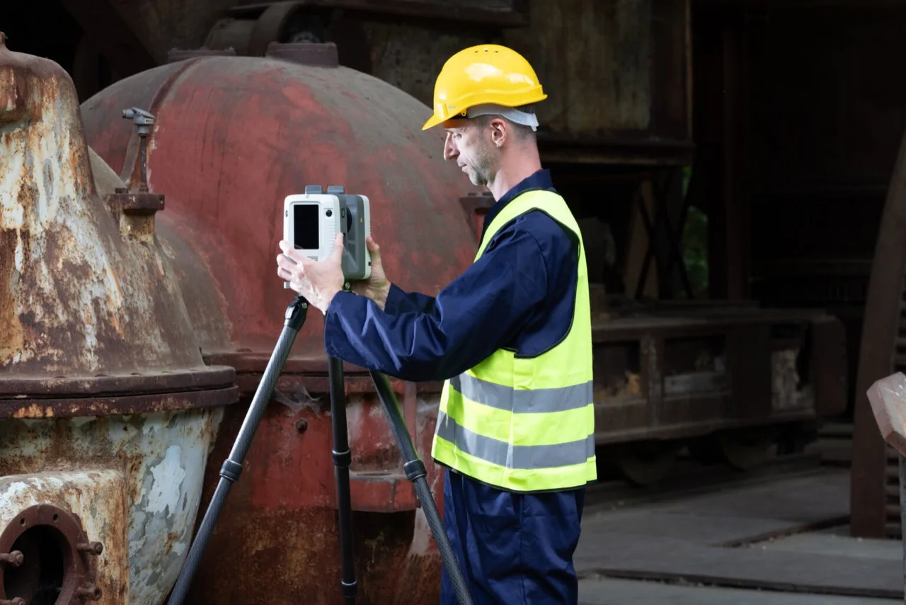
Artec positions Ray II as a stationary long-range scanner for AEC use, and its geometry fits that category: 360° horizontal and 300° vertical field of view with 0.5–130 m manufacturer-stated range. That places it firmly in the stationary TLS class, not in SLAM-based walk-through capture and not in handheld close-range scanning. It also does not replace total stations or RTK systems, which serve different roles in control and coordinate positioning. [1] [4]
| Class | Typical strength | Typical constraint | Typical role in construction |
|---|---|---|---|
| TLS | Dense fixed-position capture with broad scene coverage | Requires setup locations, overlap, and registration discipline | As-builts, façades, interiors, controlled documentation |
| SLAM | Fast movement through complex spaces | More dependence on drift management and weaker absolute control by itself | Rapid walk-throughs and large-area reconnaissance |
| Handheld | Flexible short-range access in tight spaces | Less suited to long-range scene capture | Local detail, equipment, tight interiors |
| Total station / RTK | Control, coordinates, and georeferencing | Not a dense surface-capture method | Control network, layout, authoritative positioning |
Read that table as a workflow map, not a product ranking. Ray II belongs in the TLS column, so it should be judged mainly on setup efficiency, registration behavior, control integration, and deliverable fit. [1] [4]
How Artec Ray II Works (Time-of-Flight TLS + WFD)
Artec Ray II is a time-of-flight terrestrial laser scanner. It emits laser pulses, measures return time, and computes distance from that time measurement. Artec describes the scanner as time of flight enhanced by Waveform Digitising (WFD), which means the returning signal is processed in a way intended to improve measurement handling. In field terms, Ray II is a stationary pulse-based TLS system for large scenes rather than a close-range structured-light device. [1]
The safety classification matters, but in a limited way. Artec lists Ray II as a Class 1 laser operating at 1550 nm in accordance with IEC 60825-1:2014. On a construction site, that means the emitted beam is classified within the standard’s normal-operation safety limits, but it does not remove ordinary site hazards such as tripod placement, line-of-sight management, exclusion zones, access control, or compliance with the manufacturer’s operating procedures. [1]
Ray II sweeps a wide scene from a fixed setup, with a manufacturer-stated 360° horizontal and 300° vertical field of view. It is not a structured-light scanner and not a SLAM mapper. It is a stationary TLS instrument built around measured sweeps, point clouds, and registration-driven workflows. [1]
Ray II Specs That Matter on Construction Sites
On site, the most useful Ray II numbers are the ones that affect setup count, sightlines, and occlusions. Artec’s manufacturer-stated geometry is 360° horizontal and 300° vertical with 0.5–130 m range. That is enough reach for many interior, exterior, and infrastructure tasks, but it does not remove the realities of partitions, columns, parapets, parked equipment, or inaccessible tripod locations. Wide field of view reduces blind spots per station; it does not eliminate them. [1]
Resolution mode is where spec-sheet reading often goes wrong. Ray II’s documented settings are Low at 12 mm @ 10 m with 130 m maximum range, Medium at 6 mm @ 10 m with 130 m maximum range, and High at 3 mm @ 10 m with only 65 m maximum range. The finest published spacing does not extend to the full 130 m reach. For construction scanning, that matters because façade distance, atrium span, or plant-room detail may force a tradeoff between finer spacing and longer reach, even on the same project. [3]
Productivity needs similar caution. The scanner’s manufacturer-stated capture rate is up to 2,000,000 points per second, and published scan times at 10 m range from 26 seconds to 1 minute 42 seconds without texture, or 1 minute 26 seconds to 2 minutes 42 seconds with texture, depending on resolution. Those are scan durations, not full station-cycle durations. Real productivity also includes tripod moves, leveling, path clearance, target or control work, and QA checks. Imaging specs such as the 36 MP 3-camera system, 432 MPx raw data, and automatic 5-bracket HDR help with color context and visual review, but they do not substitute for alignment quality. [1] [2]
| Manufacturer-stated Ray II item | Value | Why it matters on site |
|---|---|---|
| Field of view | 360° horizontal / 300° vertical | Broad coverage from a single setup |
| Range | 0.5–130 m | Long-range stationary capture |
| 3D point accuracy | 1.9 mm @ 10 m; 2.9 mm @ 20 m; 5.3 mm @ 40 m, at 68% confidence | Device-level accuracy context, not registered-project accuracy |
| Angular / range accuracy | 18 arcsec (0.87 mm @ 10 m); 1.0 mm + 10 ppm | Helps explain how error grows and combines |
| Resolution modes | 12 mm, 6 mm, 3 mm @ 10 m | Density choice must match task |
| High-mode max range | 65 m | Finest spacing does not reach full 130 m range |
| Scan times @ 10 m | Without texture: 1:42, 0:51, 0:26; with texture: 2:42, 1:51, 1:26 for 3, 6, 12 mm modes | Throughput input, not whole-station productivity |
| Capture rate | Up to 2,000,000 points/sec | Fast raw acquisition |
| Imaging | 36 MP 3-camera system; 432 MPx raw; HDR automatic 5 brackets | Better visual context and pano-based review |
| Battery / power | 2 × Leica GEB364 internal Li-Ion batteries; typically up to 4 h | Core runtime planning |
| Workday claim | 8 h only as an operational claim with two installed batteries plus two standby hot-swappable spares | Different from the internal-battery runtime spec |
| Size / weight | 120 × 240 × 230 mm; 5.35 kg without batteries | Handling and transport planning |
| Environment | IP54; operating −5° to +40°C; extended low-temp operation −10° to +40°C | Useful but limited site envelope |
All values in the table above are manufacturer-stated. [1] [2] [3]
Spec interpretation checklist
- Choose range first, then point spacing. [1] [3]
- Do not assume 3 mm mode is available out to 130 m. [3]
- Treat scan time and point rate as throughput inputs, not as quality guarantees. [2]
- Separate the internal battery runtime spec from the longer operational claim that assumes charged spare batteries. [1] [2]
- Check temperature and IP rating against actual site conditions, not against a best-case brochure reading. [1]
Performance Metrics Without the Hype: Accuracy → Registration → Georeferencing → BIM
Accuracy, precision, and resolution are related, but they are not interchangeable. Accuracy is closeness to the true value. Precision is repeatability. Resolution, or point spacing, describes sampling density. Dense sampling does not guarantee accurate geometry, and accurate single observations do not guarantee a good registered building-scale cloud. In point cloud registration and scan-to-BIM work, confusing those terms is one of the fastest ways to overread a spec sheet. [8] [9]
Ray II’s core accuracy figures need careful reading. Artec lists manufacturer-stated 3D point accuracy as 1.9 mm at 10 m, 2.9 mm at 20 m, and 5.3 mm at 40 m, with all accuracy specifications stated at 68% confidence. The same spec sheet lists 18 arcsec angular accuracy, equivalent there to 0.87 mm at 10 m, and range accuracy of 1.0 mm + 10 ppm. It also lists range noise, at 89% albedo and for single-shot measurements, of 0.4 mm at 10 m and 0.5 mm at 20 m. These are useful device-level descriptors. They are not field-registered project tolerances, and they do not tell you by themselves how well a multi-setup scan network will hold together across floors, shafts, exterior stations, or shared coordinates. [1]
Confidence and inference limits
- Ray II’s published point-accuracy values are manufacturer-stated at 68% confidence, not at a 95% confidence level and not as a project tolerance. [1]
- You cannot infer final registered-cloud accuracy, georeferenced control accuracy, or BIM modeling tolerance from the brochure alone. [1] [8]
- The practical accuracy chain is: device measurement → registration → control/georeferencing → modeling tolerance. [8] [9]
That gap between device and deliverable grows as projects become larger and more complex. A 2024 Buildings case study of seven building point clouds reported 490 to 1392 scanning stations and found common registration errors around the 5 cm range in complex geometries such as stairways. NIST’s TLS review also notes that range errors can range from sub-millimeter to several millimeters, while angle uncertainties are often in the tens of arc-seconds, depending on the system and conditions. The same review gives an environmental example: a 10°C temperature difference or a 35 hPa pressure difference may produce about 1 mm of distance error over 100 m. The practical question is not “Is the scanner millimeter accurate?” but “Can this project’s full workflow hold the required tolerance after registration, control, and modeling?” [8] [10]
Workflow: Construction Site Laser Scanning with Ray II → Artec Studio → Autodesk
A good Ray II workflow starts before the first scan. Plan station locations around line of sight, overlap, and occlusions rather than nominal field of view alone. If the deliverable needs defensible georeferencing, bring a control strategy into the plan instead of assuming registration convenience features are enough. Artec describes the scanner’s VIS as a system that tracks scanner position relative to the previous setup in real time, which can help with alignment workflow and pre-registration, but it is not a substitute for survey control. On active jobsites, also plan for moving crews, equipment, reflective hazards, and vibration sources that can compromise capture or force rescans. [1] [3]
In the office, registration QA should happen before export. Artec Studio 20 supports imports including PLY, STL, OBJ, PTX, BTX, STEP/STP, IGES/IGS, X_T, SAT, E57, RCP, and USD. It exports point clouds to E57, RCP, PTX, BTX, and custom text, with meter units for E57, RCP, and PTX and micron units for BTX. It can also embed a panorama into E57, which can help with visual review in third-party software. On the Autodesk side, ReCap supports import of formats including E57, PTX, and RCS and export of E57, PTS, and RCP/RCS, including structured E57 export. Revit links .RCP and .RCS files, and Autodesk states that an .RCP file groups one or more .RCS scan files. In practice, the handoff problem is usually not whether the software can open the file, but whether the team preserved registration quality, units, and coordinates through the pipeline. [5] [6] [7]
Within the Artec Line: When Ray II Fits Better Than Other Artec Approaches
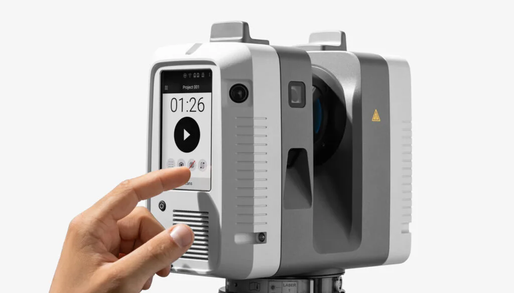
Within Artec’s AEC positioning, Ray II is the stationary long-range option for jobs such as as-built verification, clash detection, and renovation planning. The real question is not which scanner is “best” in the abstract, but whether the project rewards long-range tripod capture and later reuse of a dense registered cloud. [4]
Ray II fits best when you need stable fixed setups, long sightlines, and room- or site-scale geometry from a stationary TLS workflow. It is a weaker fit when the job depends on continuous movement through tight spaces, frequent elevation changes, or minimizing setup count above almost everything else. If the core requirement is authoritative control rather than dense surface capture, a survey-led workflow may still need to anchor the project, with scanning supporting it rather than replacing it. [1] [4] [18] [19]
Applications by Job Class
For interiors, renovation as-builts, and MEP-heavy spaces, Ray II makes the most sense when the project needs a dense, reusable record of existing conditions and can tolerate tripod-based capture. Large rooms, plant areas, shafts, and overhead service zones benefit from long line of sight and broad angular coverage, especially when the scan will feed coordination, clash checking, or later scan-to-BIM work. Artec’s AEC materials position Ray II around as-built verification, clash detection, and renovation planning, which fits this use class well. What still matters is occlusion management, not just nominal range: crowded ceilings, cable trays, duct branches, and equipment lines can force more setups than the spec sheet suggests. [1] [4] [8]
For façades, bridges, tunnels, and infrastructure segments, the appeal is different. Here the scanner’s long-range stationary geometry can reduce the number of capture positions if sightlines are good. But long range does not solve everything. NIST’s review is a reminder that performance depends on conditions and error sources, and the right capture class still depends on access, weather, contrast, reflectivity, and how much absolute control the project requires. Corridor mapping is the borderline case: Ray II can capture corridor sections well, but if the priority is continuous movement and frequent repositioning, a mobile method may fit better. [1] [8]
- Pick TLS when you need dense fixed-position capture of interiors, façades, plant rooms, or controlled as-built documentation.
- Pick SLAM when movement through the site matters more than fixed-station discipline.
- Pick handheld when close-range detail or maneuverability is the main constraint.
- Pick a drone-based workflow when the geometry is elevated, exterior, or difficult to access safely from the ground.
- Pick survey instruments when control, coordinates, or authoritative positioning are the primary deliverables. [18] [19]
- Pick a hybrid scan-plus-survey workflow when georeferencing has to be defensible and documented. [8] [11]
- Avoid assuming one tool should handle interiors, infrastructure, rapid walk-throughs, and regulated control equally well.
Limitations & Site Reality
Ray II is strongest when the use case matches the rubric: fixed setups, broad coverage, controlled registration, and practical downstream interoperability. Once the site departs from that pattern, the limitations show up in workflow, not just in the spec sheet. [1] [3]
Artec’s own Ray II documentation is explicit about several measurement risks. Highly reflective surfaces such as polished metal or gloss paint, highly absorbent dark surfaces, and translucent materials such as clear glass are all unfavorable. Rain, snow, and fog can reduce measurement quality. Direct sun can increase range noise, and scanning against the sun or a bright spotlight can overwhelm the receiver in parts of the scene. Condensation after rapid temperature changes can create measurement errors, and dust, fingerprints, or moisture on the rotating-mirror protection glass can cause considerable errors. On site, that translates into straightforward discipline: keep optics clean, do not assume rain is harmless, treat glass and gloss as problem surfaces, and plan around sun angle where possible. [3]
IP54 should be read plainly. The “5” means dust-protected, and the “4” means protected against splashing water from all directions under the IEC 60529 code system. That is useful for dusty jobsites and incidental splash exposure, but it is not the same as hose-down protection, submersion tolerance, or carefree operation in persistent rain, mud, fogged optics, or water-shedding reflective surfaces. Artec’s manufacturer-stated operating range is −5° to +40°C, with extended low-temperature operation to −10° to +40°C under stated conditions. Those are workable limits, but they still require field judgment. [1] [21]
Compliance Note (U.S.): When Scanning Crosses into Regulated Surveying
This is not legal advice, and the exact boundary varies by state. If a project requires authoritative georeferencing, boundary-related positioning, control deliverables, or maps and databases intended to represent authoritative locations, check the applicable state board rules and involve a licensed surveyor where required. NCEES Model Law language treats the practice of surveying broadly enough to include professional services using mathematics, geodesy, and photogrammetry, including geometric measurement and the development of survey products such as graphics, data, maps, plans, reports, descriptions, or projects. [18]
NCEES Model Rules add a second practical distinction: there is a difference between using georeferenced data as a reference for planning or infrastructure management and using data to establish authoritative locations or survey deliverables. The same rules also describe activities that must be done by or under the responsible charge of a professional surveyor. A Massachusetts regulation example makes the same caution concrete by stating that when integrating LiDAR mapping products provided by others, the surveyor is presumed to exercise due care in evaluating qualifications, checking conformance with standards, and performing sufficient independent conformance checks. [19] [20]
Research & Market Context: Why Scan-to-BIM Is Still Hard
Scan-to-BIM remains difficult because capture is only one part of the chain. Tang et al. describe the workflow as data collection, preprocessing or registration, and BIM modeling, and the later stages still require interpretation, segmentation, modeling choices, and tolerance decisions that are only partly automated. ISO 19650-1 keeps the framing honest: BIM is about information management, not just geometric capture. That is why downstream modeling burden deserves a place in the buying rubric. A faster or denser point cloud can help, but it does not remove the work of turning measured geometry into an information-managed deliverable that fits project standards and intended use. [9] [13]
Verdict: Is Artec Ray II the Best 3D Scanner for Construction?
Artec Ray II is a strong 3D scanner for construction when the rubric favors delivered accuracy planning, range and coverage efficiency, a deliberate registration workflow, workable interoperability, and fixed-position TLS capture. Its strengths are clear in the manufacturer-stated numbers and official documentation: broad 360° / 300° coverage, up to 130 m range, fast acquisition, standard point-cloud export paths, and credible device-level accuracy figures published at 68% confidence. Its limits are just as clear: the finest 3 mm mode reaches only 65 m, VIS is not survey control, and site conditions such as glass, reflective metal, rain, condensation, and dirty optics can materially degrade results. [1] [2] [3] [5]
So, is it the best? Sometimes, for the right job class. Large interiors, renovation as-builts, façade capture, plant areas, and other stationary capture tasks are where it makes the most sense. It is less convincing where the job is dominated by constant movement, severe weather exposure, or survey-regulated coordinate deliverables. Before buying, run a pilot with a defined control plan, a field-check or QA method, and a deliverable tolerance that matches the real use case. Also keep the evidence boundary in mind: in the reviewed source set, no reliable independent standardized Ray II field-validation study was found as of July 28, 2026, so published Ray II performance figures should still be treated as manufacturer-stated device specs rather than guaranteed project outcomes.
FAQ
Is Artec Ray II the best 3D scanner for construction?
Not universally. Artec Ray II is a strong option when the project rewards stationary TLS, long reach, broad coverage, and a disciplined registration workflow. That makes it a plausible fit for large interiors, renovation as-builts, façades, and plant areas. It is less persuasive when the job is dominated by rapid move-through capture, severe weather, or survey-regulated georeferencing. Its published range and accuracy figures are manufacturer-stated, and in the reviewed source set no reliable independent standardized Ray II field-validation study was found as of July 28, 2026. [1] [3] [8]
What is terrestrial laser scanning (TLS) in construction, and how is it different from SLAM?
TLS is fixed-position laser scanning, usually from a tripod, used to capture dense point clouds of buildings, rooms, façades, and infrastructure. SLAM-based systems capture while moving through the environment and solve position continuously. In practice, TLS usually gives a more deliberate setup and registration workflow, while SLAM prioritizes mobility and speed. For construction teams, the choice is less about one technology being better and more about whether the deliverable needs fixed-station control or rapid movement through the site. [1] [4] [9]
Can Artec Ray II data be used in Revit (RCP/RCS workflow)?
Yes. Revit links .RCP and .RCS point cloud files, and Autodesk states that an .RCP file groups one or more .RCS scan files. Artec Studio can export Ray or Ray II point clouds to E57, RCP, PTX, BTX, and custom text, while ReCap supports import of E57, PTX, RCS, and other point-cloud formats and export of E57, PTS, and RCP/RCS. In practice, the important part is not just file compatibility but clean registration, correct units, and a consistent coordinate strategy before handoff. [5] [6] [7]
Does Artec Ray II automatically create a BIM model?
No. Ray II captures point-cloud data; it does not automatically deliver a finished BIM. The classic workflow remains data collection, preprocessing or registration, and BIM modeling. That last stage still requires interpretation of the measured geometry into modeled objects, relationships, and project information structures. ISO 19650-1 is useful here because it frames BIM as information management, not simply collected geometry. Ray II can be part of a scan-to-BIM pipeline, but it does not eliminate the modeling step. [9] [13]
What accuracy can I expect on a real construction project?
Separate device-level specs from project-level outcomes. Artec publishes Ray II 3D point accuracy as 1.9 mm at 10 m, 2.9 mm at 20 m, and 5.3 mm at 40 m, all at 68% confidence. Those are manufacturer-stated values, not guarantees for a registered building cloud or BIM deliverable. Real results also depend on overlap, registration, control, geometry complexity, environmental conditions, and modeling tolerance. A building-scale case study found common registration errors around 5 cm in complex geometries, which shows how quickly project results can diverge from single-device specs. [1] [8] [10]
Expert: How should I field-verify TLS performance?
Start with field procedure, not brand claims. ISO 17123-9:2018 is the standard reference for field procedures to determine and evaluate the precision, meaning repeatability, of terrestrial laser scanners and related equipment in building, civil engineering, and surveying measurements. ASTM E3125-17R25 provides a different but complementary framework for evaluating point-to-point distance performance of medium-range spherical-coordinate 3D imaging systems. In practice, the goal is to verify whether the scanner and workflow meet your project tolerance under your field conditions, not whether a brochure sounds impressive. [11] [12]
Expert: When do georeferenced deliverables require a licensed surveyor in the U.S.?
When the deliverable crosses from internal planning or coordination into authoritative location, control, or survey product territory, check state rules and involve a licensed surveyor where required. NCEES Model Law and Model Rules both treat surveying broadly enough to cover many measurement-based geospatial outputs, while also distinguishing between general informational uses and authoritative location uses. A point cloud used only as design reference is not the same as a regulated survey deliverable. The exact line varies by jurisdiction, which is why state-board review matters. [18] [19] [20]
Related on 3D Mag
Sources
- Artec Ray II specifications PDF
- Artec Ray II product page
- Artec Ray II documentation: scanning conditions and settings
- Artec AEC solutions page
- Artec Studio 20 docs
- Autodesk Revit 2026: Insert a Point Cloud File
- Autodesk ReCap Help: Supported File Formats
- NIST TLS performance evaluation review
- Tang et al. scan-to-BIM paper
- Buildings point cloud quality case study
- ISO 17123-9:2018 listing
- ASTM E3125-17R25 page
- ISO 19650-1:2018 listing
- Trimble X9 product page
- Trimble X9 spec sheet viewer
- FARO Focus product page overview
- FARO Focus AEC brochure PDF
- NCEES Model Law
- NCEES Model Rules
- Massachusetts surveying standards example
- TUV IP testing explainer