
Summary
Artec Ray II is a fit-for-purpose 3D laser scanner for buildings when the job is large-scale, stationary terrestrial laser scanning (TLS) with disciplined setup planning, not when the workflow is dominated by rapid walkthrough capture or ultra-close detail. Artec states a 0.5–130 m range and manufacturer-stated 3D point accuracy of 1.9 mm at 10 m, 2.9 mm at 20 m, and 5.3 mm at 40 m, but those instrument figures are not the same as final as-built or BIM tolerance. [1]
This evaluation starts from the deliverable rather than the brochure. The useful questions are whether the buyer will accept the tolerance language, whether the control and registration plan are defensible, whether site conditions support stable capture, and whether the export path fits scan-to-BIM or CAD handoff. That is why USIBD LOA Specification Version 3.1 is the buyer-facing frame here, and why registration QA matters as much as range. It also matters that Artec’s high-resolution mode does not retain the full 130 m headline range, and that Artec Studio’s documented global registration workflow depends on targets, with Align as the fallback when targets were not captured. [14] [15] [4] [5] [11]
What Artec Ray II is (and what it is not)
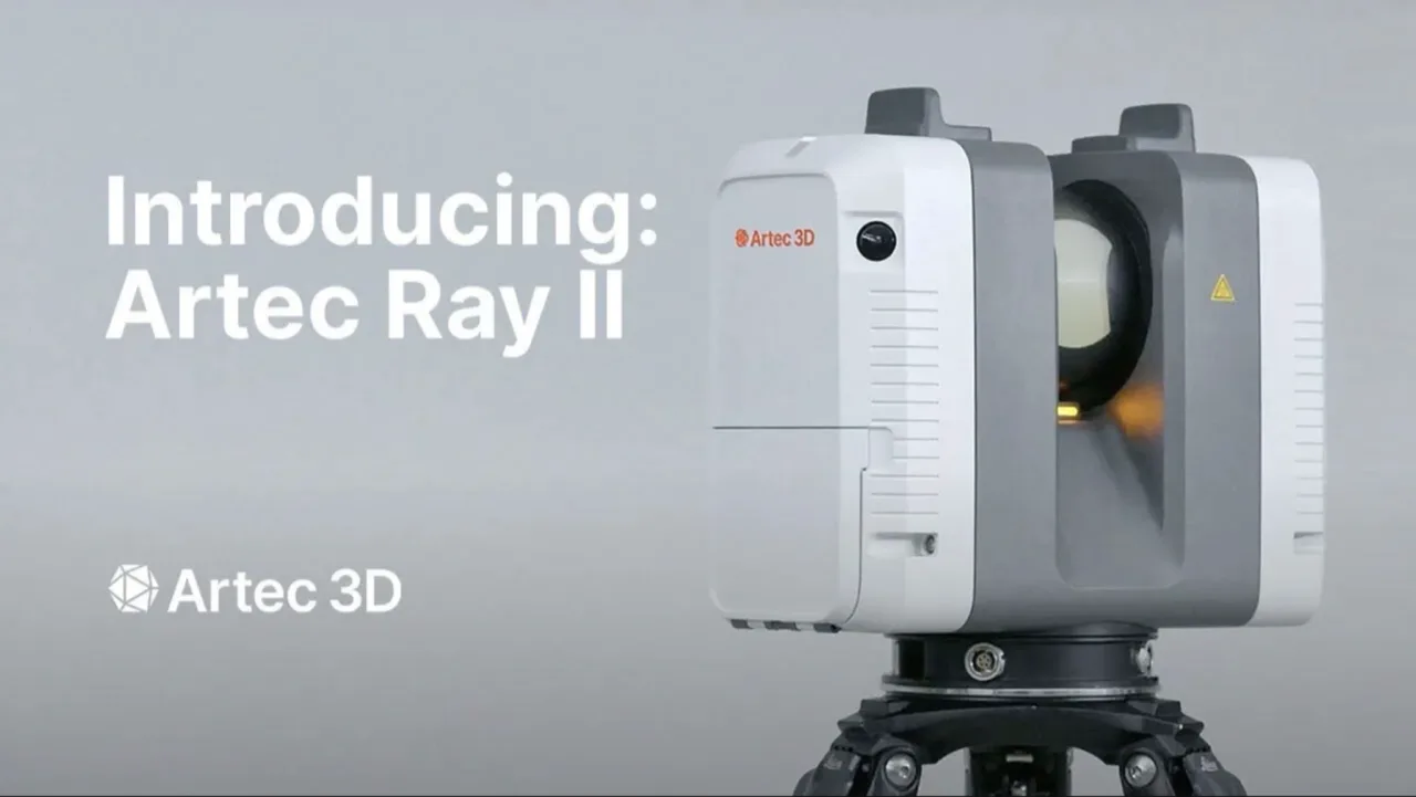
Artec Ray II is a stationary, tripod-based terrestrial laser scanner. In practice, that means a long-range LiDAR instrument that measures distances to surfaces and records them as a point cloud: a set of 3D points describing the scene. Its published 0.5–130 m range and 360° horizontal / 300° vertical field of view place it in building-scale capture territory, but it is still a fixed-position scanner rather than a mobile SLAM mapper, a handheld detail scanner, or a virtual-tour camera. [1] [4]
That distinction matters because buildings are never captured from one setup. A Ray II survey is a chain of stations with overlap, access planning, and registration afterward. The scanner is also constrained by line of sight and surface behavior. Artec’s documentation identifies highly reflective surfaces, highly absorbent black surfaces, and translucent surfaces such as clear glass as unfavorable, and it warns that rain, snow, fog, direct sun, condensation, and dirt can degrade results or produce missing data. [4]
Spec sheet vs. building deliverables — the framework this article uses
Raw scanner specs are difficult to compare because outcomes depend on geometry, conditions, and registration quality, not just on headline instrument numbers. NIST’s 2021 TLS review notes that scanner comparison is hard because specifications are idiosyncratic and test contexts differ. DVW’s registration guideline adds the more practical warning: once a project is built from multiple scan positions, registration becomes part of the uncertainty budget, and false or weak registrations need to be detected early rather than accepted because the cloud looks plausible. That is why this article treats registration as part of measurement, not as a cosmetic merge step. [12] [13] [11]
From a buyer’s perspective, tolerance language should come before device shopping. USIBD’s public LOA page confirms that LOA Specification Version 3.1 is the current framework and that the release includes guidance on using standard deviation to specify tolerances. The USIBD store page labels the current release as LOA Specification Version 3.1 (2025). But the public pages do not expose the numeric LOA table in a way that can be verified here, so the correct buyer-facing fallback is: no reliable figure found in a publicly accessible USIBD page for the numeric LOA table; consult the LOA v3.1 PDF. [14] [15]
ISO 17123-9 and ASTM E3125 are useful, but for different reasons. ISO 17123-9 specifies field procedures for determining and evaluating TLS precision or repeatability and explicitly says those tests are not acceptance or broader performance evaluations. ASTM E3125 instead evaluates point-to-point distance performance against manufacturer-stated maximum permissible errors under stated conditions, and the same standard notes that testing may be repeated under different environmental or reflectance conditions. A producer accuracy claim is only meaningful when the method and conditions are visible. [9] [10]
From instrument specs to deliverable confidence
| Component | What it affects | How you verify | Where Ray II specs help / don’t help |
|---|---|---|---|
| Instrument specification | Single-scan range, speed, sampling, and manufacturer-stated accuracy. | Read the datasheet and operating documentation carefully. [1] [4] | Ray II’s range, 3D point accuracy, angular accuracy, range accuracy, scan times, and mode limits are useful starting points, not deliverable proof. [1] [4] |
| Registration | Whether multiple scans share a stable common coordinate system. | Review target deviations, overlap quality, checkpoints, and saved processing outputs. [5] [11] | Ray II documentation helps with workflow and QA steps, but registration can still add more error than the instrument itself. [5] [11] |
| Control and georeferencing | Whether the project sits in a defensible site or survey reference frame. | Use an explicit control plan and independent checks. [11] | Ray II alone does not guarantee project control; that is a survey design issue, not a brochure line. [11] |
| Deliverable acceptance | Whether the final cloud or model meets the contract requirement. | Use LOA or equivalent tolerance language before fieldwork. [14] [15] | Ray II specs can inform feasibility, but the acceptance threshold belongs to the project requirement, not the scanner marketing. [14] [15] |
Glossary — stop sloppy accuracy language
Scanner comparisons fall apart quickly when accuracy, resolution, density, and registration are treated as interchangeable. NIST defines accuracy as closeness to a reference value and says it combines trueness and precision. NIST also defines resolution as the ability to detect small changes and warns that displayed digits do not prove actual resolution. DVW’s registration guidance is equally important: registration is the act of transforming point clouds into a common coordinate system, not proof that the result is correct. [7] [8] [11]
| Term | Short meaning | Common misuse to avoid |
|---|---|---|
| Accuracy | Closeness to a reference value; NIST frames it as combining trueness and precision. [7] | Treating a clean-looking cloud as proof of correctness. |
| Trueness | How close results are to the reference on average. | Using it as a synonym for precision. |
| Precision | How tightly repeated results cluster. | Confusing repeatable error with low error. |
| Repeatability | Similarity of repeated results under similar conditions. | Calling one good scan “repeatable.” |
| Uncertainty | The remaining doubt around a result. | Ignoring it once a scanner spec is known. |
| Resolution | Ability to detect small changes; displayed digits do not indicate true resolution. [8] | Reading more meaning from decimals than the system supports. |
| Point spacing | Distance between neighboring sampled points. | Assuming it is uniform everywhere in the scene. |
| Point density | Number of points in a given area or volume. | Equating density with accuracy. |
| Registration | Transforming scans into a common coordinate system. [11] | Treating station merge as the same as georeferencing. |
| Georeferencing | Placing the registered dataset in a project, survey, or map reference frame. | Using rough alignment as a substitute for control. |
For building surveying, the practical split is straightforward: accuracy and uncertainty describe trustworthiness, resolution and point spacing describe sampling, and registration plus georeferencing describe spatial organization. If those terms blur together, brochure comparisons become weaker than they look. [7] [8] [11]
How Ray II captures buildings
Ray II is a time-of-flight LiDAR scanner. It measures distance by sending out laser pulses and timing their return from scene surfaces, which is why it behaves like a building-survey TLS rather than a photographic device. The Ray II documentation lists a 1550 nm laser, 1.5 μJ maximum pulse energy, 0.5 ns pulse duration, 2 MHz maximum pulse repetition frequency, 0.5 mrad beam divergence, and 100 Hz mirror rotation. In practice, one scan station never sees everything, so occlusion is built into the method. Walls hide recesses, pipework hides back faces, and façades hide geometry behind reveals or parapets. Multiple setups are a requirement, not a sign that the scanner underperformed. [3] [4]
Angular performance is easy to underestimate. Artec states angular accuracy as 18 arcseconds and also expresses that as 0.87 mm at 10 m. That matters because a small pointing error becomes a larger positional shift as distance increases. Range accuracy is listed separately as 1.0 mm + 10 ppm, so beam-direction error and along-beam distance error should not be treated as the same thing. [1]
Ray II’s sampling settings are mode-specific. Artec lists 3 / 6 / 12 mm at 10 m, which is a spacing reference at that distance rather than a promise of uniform point spacing across the whole scene. Spacing grows as range increases and varies with scene geometry. Artec’s scan-settings documentation adds the key caveat: low mode at 12 mm and medium mode at 6 mm both reach 130 m, but high mode at 3 mm reaches 65 m. The real field choice is not “maximum detail at any distance,” but how much density you need at the distances your building actually presents. [1] [4]
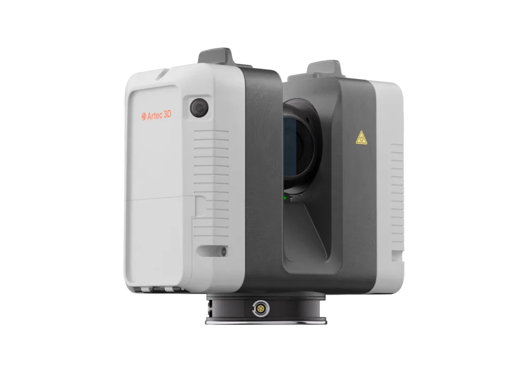
Artec Ray II specs that matter for building surveying
For building work, Ray II’s numbers only become useful when read together. Artec’s datasheet states a 0.5–130 m range, 360° / 300° field of view, 3 / 6 / 12 mm settings at 10 m, and a 3D capture rate up to 2,000,000 pts/sec. Those figures sound straightforward until scan mode is added back in: the documented high mode reaches 65 m, while low and medium modes reach 130 m. For façade work, large interiors, or plant spaces, that caveat matters more than the headline range by itself. [1] [4]
The accuracy lines also need to be separated. Artec states 3D point accuracy as 1.9 mm at 10 m, 2.9 mm at 20 m, and 5.3 mm at 40 m; angular accuracy as 18 arcseconds; and range accuracy as 1.0 mm + 10 ppm. The same sheet lists range noise as 0.4 mm at 10 m and 0.5 mm at 20 m, but specifically under 89% albedo and single-shot conditions. That means the noise values are conditional, not universal. The datasheet also says that all accuracy specifications are given at 68% confidence according to JCGM 100:2008 unless otherwise noted. Ray II publishes useful manufacturer-stated instrument numbers, but they still need to be read alongside surface reflectance, environment, registration method, and confidence language. [1]
Before fieldwork, verify that the chosen mode, battery plan, and environmental limits match the site. Artec’s datasheet lists operating temperature as -5°C to +40°C, extended low-temperature operation to -10°C only under stated startup conditions, and IP54 protection. Those are project constraints, not footnotes. [1]
Key Ray II numbers to verify before a building survey
- Range: 0.5–130 m. [1]
- Field of view: 360° horizontal / 300° vertical. [1] [4]
- 3D point accuracy: 1.9 mm at 10 m, 2.9 mm at 20 m, 5.3 mm at 40 m. [1]
- Angular accuracy: 18 arcseconds, also stated as 0.87 mm at 10 m. [1]
- Range accuracy: 1.0 mm + 10 ppm. [1]
- Range noise: 0.4 mm at 10 m and 0.5 mm at 20 m, stated for 89% albedo and single-shot measurements. [1]
- Resolution / spacing settings: 3 / 6 / 12 mm at 10 m. [1]
- Capture rate: up to 2,000,000 pts/sec. [1]
- Scan time without texture at 10 m: 1.7 min at 3 mm, 0.85 min at 6 mm, 0.4 min at 12 mm. [1]
- Scan time with texture at 10 m: 2.7 min at 3 mm, 1.9 min at 6 mm, 1.4 min at 12 mm. [1]
- High-mode range caveat: 65 m in high mode; 130 m in low and medium modes. [4]
- Battery system: 2 × Leica GEB364 internal rechargeable Li-ion batteries, typically up to 4 h, 340 g per battery. [1]
- Environmental limits: -5°C to +40°C operating, with extended low-temperature operation to -10°C only under stated conditions; IP54 ingress protection. [1]
- Confidence note: Artec states all accuracy specifications at 68% confidence unless otherwise noted. [1]
Registration in practice — VIS, targets, and when targetless is insufficient
VIS is useful as field context because it helps track scanner movement between setups and supports onboard or pre-alignment awareness, but it is not a substitute for survey control on accuracy-critical jobs. A scan set can look visually coherent and still be weak where the deliverable actually matters. Surface and environmental problems also feed into registration stability: reflective, black, or translucent materials, plus weather or condensation issues, can reduce usable geometry before registration even begins. [1] [4] [11]
Artec’s documented processing workflow is unusually clear on the target question. In Artec Studio, global registration for Ray II scans requires targets. If no spheres or checkerboard targets were present during capture, the documentation says to use Align instead. The same documentation says Artec Studio calculates deviations for target instances and clusters, lists those deviations in the Features panel, and lets the user exclude badly registered targets before re-running global registration. That is exactly the kind of QA trail building-survey work should retain. [5]
The broader warning comes from outside the vendor stack. DVW notes that registration can produce deviations exceeding the measurement accuracy of the laser scanner itself and that false registrations or network tensions should be found as early as possible. For as-builts, scan-to-BIM, or any georeferenced deliverable, keep the control points, target deviations, checkpoint results, and saved processing states instead of relying on a merged cloud by appearance alone. [11] [5]
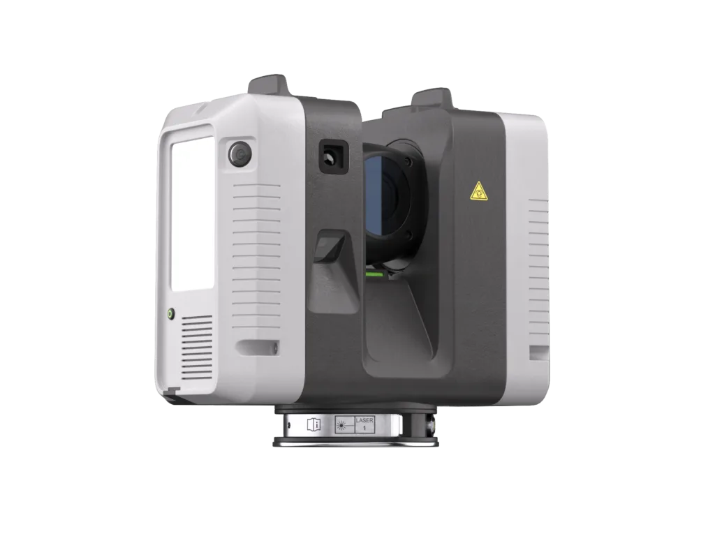
Workflow for defensible building scans
A defensible building scan starts before the scanner is powered on. Define the deliverable, acceptance criteria, and tolerance language first, then translate that into a control plan, station layout, and overlap strategy. Scan-to-BIM literature consistently treats the workflow as acquisition, preprocessing or registration, and modeling, which is a useful reminder that the cloud is an intermediate product, not the final answer. If the project references LOA, confirm the framework and then consult the LOA v3.1 PDF for any numeric table rather than inferring figures from a summary page. [20] [14] [15]
In the field, treat Ray II like what it is: stationary TLS. Place stations to break line-of-sight gaps, add overlap that supports registration from multiple directions, and use targets or checkpoints when the job requires a defensible chain of evidence. Artec’s scanning guidance warns that rain, snow, fog, sunlit surfaces, condensation, dirt, and difficult materials can all reduce capture reliability or raise uncertainty. Moving objects can also contaminate the cloud, so critical areas are worth re-scanning rather than assuming cleanup later will solve everything. [4] [11]
In the office, registration is a QA gate, not a clerical step. Review target deviations, isolate or remove bad targets where needed, and check the registered result against independent geometry or checkpoints before trusting the merged cloud. Once the geometry is defensible, Artec Studio supports point-cloud export to E57, RCP, PTX, Custom Text File Format, and BTX, and CAD primitive export to STEP, IGES, and X_T. That export flexibility is useful, but it does not rescue weak acquisition or weak registration. [5] [6] [20]
Minimum workflow checklist for defensible building scans
- Define the deliverable and acceptance criteria before site work begins. [14] [20]
- Set the LOA or equivalent tolerance target and document the control plan. [14] [15]
- Plan station spacing and overlap around occlusion, access, and geometry, not convenience alone. [11]
- Capture independent control points or checkpoints, not just scanner-to-scanner ties. [11]
- Record a registration report, residuals, or equivalent QA output from the processing stack. [11]
- Check target deviations and exclude bad targets before rerunning global registration when a target-based workflow is used. [5]
- Use cloud-to-cloud checks as a supplement, not as the only evidence of quality. [11]
- Keep weather, surface, and movement notes with the scan log. [4]
- Export the handoff format that matches the downstream BIM or CAD workflow. [6]
Limitations and failure modes
Occlusion is the first failure mode in building surveying. Columns, deep recesses, pipe racks, cable trays, and soffits create no-view zones where the scanner simply cannot observe the surface from one setup. Weak geometry is the related problem: long corridors, repetitive façades, and visually uniform areas can make registration less stable because the overlap carries too little distinctive structure. The practical mitigation is usually more stations, more cross-views, and fewer assumptions that one long run will register cleanly. [11]
Surface interaction is the second major problem. Artec explicitly identifies highly reflective surfaces, highly absorbent black surfaces, and translucent surfaces such as clear glass as unfavorable. It helps to separate three outcomes. A no-return case means the scanner records little or nothing useful from the surface. A noisy-return case means points are recorded, but with unstable or scattered placement. A false-geometry case means the cloud shows a plausible but wrong surface, often from complex reflection behavior or mixed returns. Mitigation usually combines a changed station angle, more overlap, surface treatment when allowed, and checking suspect areas against other evidence instead of trusting the first acceptable-looking cloud. [4] [1]
Condition sensitivity is not theoretical. Ray II’s range-noise figures were stated under 89% albedo and single-shot conditions, which already tells you they are conditional rather than universal. Outdoors, sun can increase range noise or even dazzle the receiver in some areas; rain, snow, fog, condensation, and dirt can all reduce usable data or introduce errors. Add multiple stations, file management, and registration review, and the real burden becomes operator discipline as much as hardware capability. The mitigation is straightforward: scan in stable conditions when possible, protect the instrument, repeat critical stations, and budget time for QA and cleanup instead of spending it all on acquisition speed. [1] [4] [11]
Interoperability for scan-to-BIM
Ray II does not create BIM automatically. In a scan-to-BIM workflow, the scanner produces point-cloud data, not a finished building model. Independent review literature describes the generic process as data acquisition, data preprocessing or registration, and then BIM modeling. That distinction matters because a point cloud can support coordination, inspection, or authoring, but someone still has to interpret the geometry and model building elements in BIM software afterward. [20]
For handoff, Artec Studio documents point-cloud export to E57, RCP, PTX, Custom Text File Format, and BTX, plus CAD primitive export to STEP, IGES, and X_T. The same documentation notes that E57 export can embed the first-person panoramic view for scans that include photos. In practice, E57 is the neutral exchange choice many teams prefer, while RCP and PTX are common alternatives depending on the downstream environment. Those are delivery formats, not BIM creation by themselves. [6] [20]
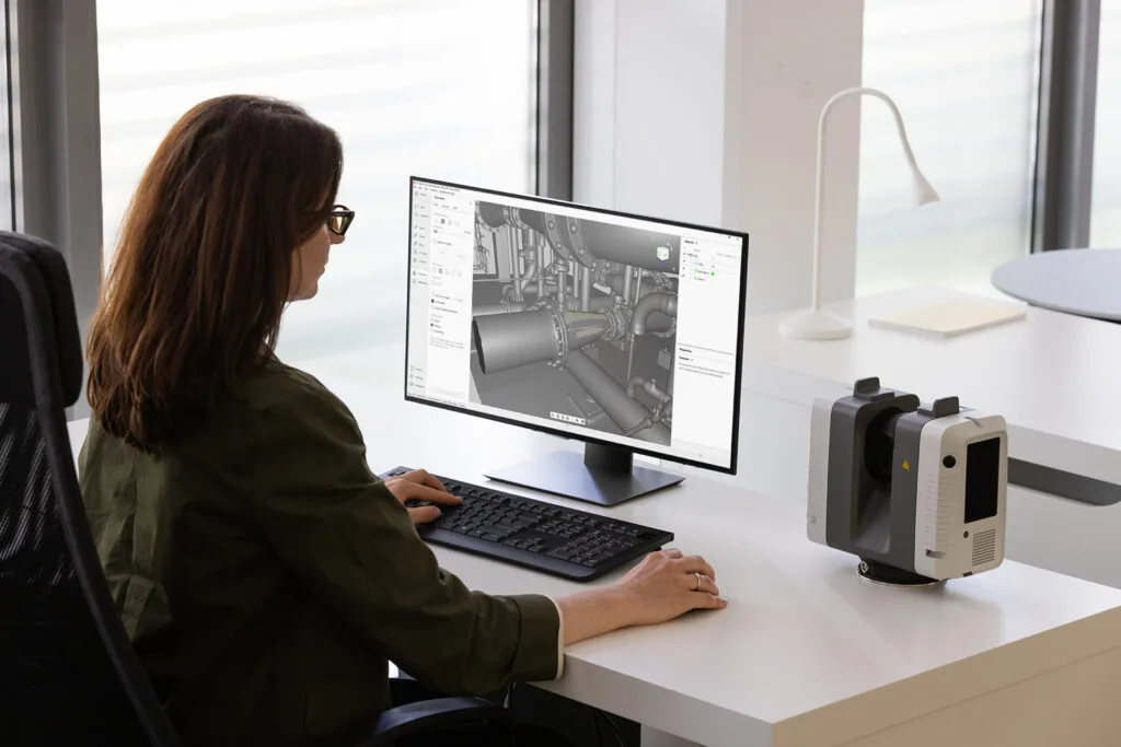
Scanner class comparison for building work
The capture class should match the deliverable, not the other way around. Scan-to-BIM literature treats accuracy, precision, point density, and resolution as separate quality terms, which is one reason a tripod TLS, a mobile SLAM system, a handheld scanner, and drone photogrammetry are not interchangeable even when they all produce 3D data. Ray II sits firmly in the TLS class: slower and more deliberate than mobile mapping, but usually more defensible when registration quality and deliverable governance matter. [20]
| Scanner class | Best fit | Strength | Main limitation |
|---|---|---|---|
| TLS | Controlled building capture from fixed stations | Strong geometry discipline and defensible QA | Needs multiple setups, overlap, and registration |
| Mobile SLAM | Fast walkthrough coverage | Speed and ease of coverage | Drift and accuracy depend heavily on trajectory and loop closure |
| Handheld | Close-range detail and small areas | Access to tight or awkward geometry | Limited range and poor efficiency for whole buildings |
| Photogrammetry-drone | Roofs, façades, and hard-to-reach exteriors | Access where tripod placement is difficult | Lighting, texture, and scale control strongly affect results |
A good buyer comparison starts by asking which class best serves the tolerance, access, and handoff requirement. For full as-builts or scan-to-BIM where the geometry may be audited later, TLS often remains the safest default. For reconnaissance, roof capture, or small-detail complements, the other classes may be the better choice. [20]
Market context — reading Ray II against other building-survey TLS headlines
Product comparisons become misleading when confidence language, albedo assumptions, and test setups are hidden. Artec states Ray II accuracy at 68% confidence. Trimble’s X9 sheet states its 3D point accuracy at 1 sigma and notes 80% albedo. ASTM E3125 is useful precisely because it frames performance as condition-dependent and measured against stated maximum permissible errors, not as a number that floats free of reflectance, distance, and environment. FARO also publishes different range headlines across the Focus Core, Focus Premium, and Focus Premium Max variants, so even a single product family does not reduce to one number. [1] [10] [17] [19]
The practical reading is simple: compare like with like, and distrust tidy rankings built from unlike conditions. Ray II’s numbers may be attractive for long-range stationary work, but they still need the high-mode range caveat and the 68% confidence note. Trimble’s X9 Premium has slightly different range and accuracy headlines under its own stated conditions. FARO’s Focus line spans different range classes altogether. A headline without its test language is not yet a useful engineering comparison. [1] [10] [17] [19]
| Device | Range headline | Accuracy headline | Conditions / caveat you must mention |
|---|---|---|---|
| Artec Ray II | 0.5–130 m. [1] | 1.9 mm @ 10 m; 2.9 mm @ 20 m; 5.3 mm @ 40 m. [1] | Artec states these at 68% confidence, and high mode reaches 65 m rather than 130 m. [1] [4] |
| FARO Focus Premium Max | 400 m. [17] | Up to 2 mm. [17] | This is a manufacturer headline for one Focus variant; the family also includes 200 m Premium and 100 m Core models, so model names matter. [17] |
| Trimble X9 Premium | 0.6–150 m. [19] | 2.3 mm @ 10 m; 3.0 mm @ 20 m; 4.8 mm @ 40 m. [19] | Trimble states these at 1 sigma and 80% albedo; the same sheet lists 360° × 282° FOV and 1000 kHz Premium scan speed. [19] |
How to choose a long range LiDAR scanner for building surveying
Start from the deliverable tolerance, not the scanner. If the client or internal QA process needs contractable language, frame it in LOA or an equivalent requirement first, then work outward into control, registration, and acceptance criteria. USIBD’s public pages confirm LOA Specification Version 3.1 and its standard-deviation guidance, but if the project depends on the numeric LOA table, consult the LOA v3.1 PDF rather than guessing from a summary page. [14] [15]
Next, translate that requirement into field method. Multiple scanner positions increase the uncertainty budget, so registration is part of the measurement chain. That means judging a candidate scanner by its real working combination of range, mode-specific spacing, scan time, environmental limits, target strategy, QA workflow, and export support. For Ray II specifically, that means reading the 0.5–130 m headline alongside the 65 m high-mode caveat, the manufacturer-stated accuracy figures, the documented target-based global registration workflow, and the available exports to E57, RCP, PTX, BTX, STEP, IGES, and X_T. [11] [1] [5] [6]
Ray II is a sensible choice when you need stationary long-range building capture, disciplined point cloud registration, and flexible handoff into downstream AEC tools. If the work is dominated by close-range detail capture or faster mobile coverage, a different scanner class, or a different Artec model, may be the better fit. [1] [6]
Verdict — when Artec Ray II is the right choice
Artec Ray II is a strong fit when the work is large-scale, tripod-based building capture: big interiors, façades, plant rooms, and site-scale as-built documentation where controlled station planning matters more than walking speed. Its manufacturer-stated range, accuracy figures, and scan-time options are credible starting points for teams that can also manage overlap, targets or checkpoints, registration QA, and handoff into E57, RCP, PTX, or BTX-based workflows. [1] [4] [6]
It is a weaker fit when the priority is rapid walkthrough capture, close-detail-centric work, or conditions that make fixed-station planning difficult. The high-mode 65 m caveat matters if you expected every mode to behave like the 130 m headline, and outdoor work is still bounded by surface response, weather, operating limits of -5°C to +40°C, and IP54 protection. In short, Ray II is not “the best” in the abstract; it is the best fit when the deliverable and the QA method both suit stationary TLS. [1] [4]
FAQ
Is Artec Ray II the best 3D laser scanner for buildings?
Only if “best” means best fit for a building deliverable that favors tripod-based TLS, controlled registration, and long-range stationary capture. Ray II is well suited to large interiors, façades, and site-scale as-built documentation, but that does not make it universally better than mobile SLAM, handheld scanning, or other TLS units for every job. The right comparison starts from tolerance language, control strategy, and export needs, not from one headline spec. [1] [11] [14]
How accurate is Artec Ray II for building surveying?
Artec states 3D point accuracy of 1.9 mm at 10 m, 2.9 mm at 20 m, and 5.3 mm at 40 m, and the datasheet says those accuracy specifications are stated at 68% confidence unless otherwise noted. That is a manufacturer-stated instrument specification, not a guarantee of final project tolerance. Delivered accuracy still depends on registration, control, surface behavior, geometry, and acceptance criteria. [1] [11]
How does VIS or targetless workflow relate to survey control and registration QA?
VIS helps with field context and tracking between setups, but it is not survey control. Artec’s processing documentation says that global registration for Ray II scans requires targets, and that Align is the fallback when spheres or checkerboards were not captured. For accuracy-critical as-builts or scan-to-BIM work, the key issue is not whether targetless alignment can work, but whether you can audit it later using checkpoints, target deviations, residuals, and control geometry. DVW’s warning that registration can exceed instrument measurement accuracy is the reason this distinction matters. [5] [11]
What is the difference between 3D point accuracy, range accuracy, angular accuracy, and range noise?
They describe different parts of the measurement chain. 3D point accuracy is the overall spatial closeness of the computed point. Range accuracy is the along-beam distance term; for Ray II, Artec states 1.0 mm + 10 ppm. Angular accuracy is the beam-direction term; Artec states 18 arcseconds and also expresses it as 0.87 mm at 10 m. Range noise is the scatter in repeated distance returns; Artec states 0.4 mm at 10 m and 0.5 mm at 20 m under 89% albedo and single-shot conditions. Resolution is separate again: it is about detecting small changes, not guaranteeing correctness. [1] [8]
What file formats can Ray II export for scan-to-BIM workflows?
Artec Studio documents point-cloud export to E57, RCP, PTX, Custom Text File Format, and BTX, plus CAD primitive export to STEP, IGES, and X_T. For scan-to-BIM, those are handoff formats rather than BIM creation by themselves. In practice, E57 is the usual neutral exchange route, while RCP and PTX are common alternatives depending on the downstream toolchain. [6]
Does Artec Ray II create BIM models automatically?
No. Ray II captures point-cloud data, and scan-to-BIM still requires preprocessing or registration plus later modeling in BIM software. Review literature describes the generic process as acquisition, preprocessing, and modeling, which is a useful reminder that the cloud is an input to BIM authoring, not a finished BIM deliverable on its own. [20]
Does Artec Ray II work outdoors and what breaks first?
Yes, but outdoor use is condition-sensitive. Artec documents unfavorable weather such as rain, snow, and fog, warns that sunlit surfaces can increase range noise or even prevent data capture in dazzled areas, and notes that dirt or condensation on the protection glass can cause considerable measuring errors. The practical failures usually appear first as reduced usable coverage, noisier returns on difficult surfaces, or a harder registration problem because field geometry forced less-than-ideal station placement. The mode choice matters too: the 130 m headline is not available in high mode, which is limited to 65 m. [4] [1]
Sources
- 1. Artec Ray II brochure/spec sheet (PDF). Manufacturer datasheet. https://cdn.artec3d.com/content-hub-files/ray-ii-web-en.pdf#page=6
- 3. Artec Ray II documentation — About. Official documentation. https://docs.artec3d.com/rayII/#laser-specifications
- 4. Artec Ray II documentation — Scanning. Official documentation. https://docs.artec3d.com/rayII/scanning.html
- 5. Artec Ray II documentation — Processing. Official documentation. https://docs.artec3d.com/rayII/process.html
- 6. Artec Studio 20 documentation — Projects/Import/Export. Official documentation. https://docs.artec3d.com/as/20/en/projects.html
- 7. NIST glossary — Accuracy. Official terminology. https://www.nist.gov/glossary-term/36846
- 8. NIST Engineering Statistics Handbook — Resolution. Official handbook. https://itl.nist.gov/div898/handbook/mpc/section4/mpc451.htm
- 9. ISO 17123-9:2018 publisher page. Standard overview. https://www.iso.org/standard/68382.html
- 10. ASTM E3125-17 publisher page. Standard scope and performance framing. https://store.astm.org/e3125-17.html
- 11. DVW Guideline 18-2022: Registration of TLS point clouds (PDF). Industry guideline. https://dvw.de/api/assets/downloads/ev/publikationen/merkblatter/18_23_dvwguideline18tlspointcloudregistration20230424.pdf
- 12. NIST publication landing page — Performance Evaluation of Terrestrial Laser Scanners – A Review. Publication metadata and date. https://www.nist.gov/publications/performance-evaluation-terrestrial-laser-scanners-review
- 13. NIST-hosted PDF — Performance Evaluation of Terrestrial Laser Scanners – A Review. Full review text. https://tsapps.nist.gov/publication/get_pdf.cfm?pub_id=930840#page=5
- 14. USIBD — Level of Accuracy landing page. Current LOA framework confirmation. https://usibd.org/level-of-accuracy/
- 15. USIBD — LOA Specification v3.1 (2025) product page. Version and availability confirmation. https://usibd.org/product/loa-version-3-1/
- 17. FARO — Focus Laser Scanners product page. Manufacturer headline specs for Focus variants. https://www.faro.com/en/Products/Hardware/Focus-Laser-Scanners
- 19. Trimble X9 spec sheet (PDF). Manufacturer specs and stated test conditions. https://d21wzbwgz8tkn8.cloudfront.net/userfiles/trimble%20×9%20spec%20sheet.pdf#page=2
- 20. Abreu, N., Pinto, A., Matos, A., and Pires, M. Procedural Point Cloud Modelling in Scan-to-BIM and Scan-vs-BIM Applications: A Review. ISPRS International Journal of Geo-Information, 2023. https://www.mdpi.com/2220-9964/12/7/260