
Summary
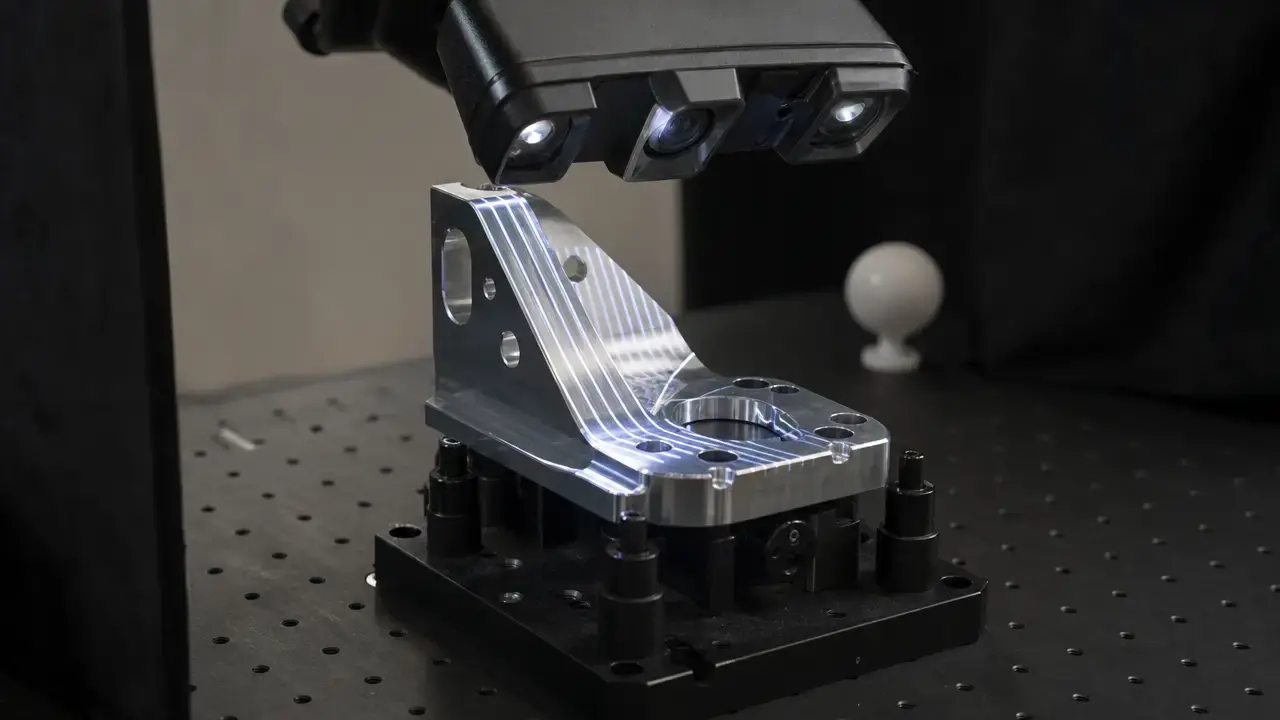
A 3d scanning spray alternative starts with controlling the capture rather than altering the part: manage stray light, viewing angle, available exposure settings, fixturing, and scan path, then validate the result against the features that matter. Try non-coating controls first, but validate; coatings may still be necessary for measurement reliability. In structured-light/triangulation work, NIST notes that shiny and dark surfaces can perform poorly, while ambient light can interfere with captured pattern intensity. [1]
Surface preparation for 3D scanning must preserve the measurement objective, part condition, and traceability. ISO 10360-13 frames optical 3D CMS performance verification around surfaces within a cooperative range, including restricted glossiness and colour characteristics. [2] This is an operational decision guide, not a product ranking.
The Fast Decision: When You Can Skip Spray — and When You Can’t
Use this as a screening sequence, not as proof that a scan is suitable for measurement. Scanner documentation can overturn general expectations: Revopoint’s MetroX table varies spray guidance by mode and surface type. [9]
Decision in 60 seconds
- Define the output: visual model, reverse-engineering reference, fit-check, or inspection result.
- Identify the surface problem: dark, glossy, metallic, transparent, oily, wet, textured, or mixed material.
- Identify the scanner and mode. For MetroX, shiny black or metal objects receive different guidance in Full Field and Auto Turntable modes than in Cross and Parallel Lines modes, while transparent or specular objects are marked as requiring spray in both groups. [9]
- Try controlled capture: reduce stray light, adjust angle and available exposure settings, and reposition the part or scanner.
- Treat tracking separately: registration support does not make missing or distorted surface data reliable.
- Inspect raw data for holes, noisy bands, doubled geometry, and drifting edges before meshing.
- Validate critical features against a suitable reference. If confidence cannot be demonstrated, change the method or consider a purpose-made coating.
Artec Studio’s Sensitivity setting is a vendor-specific example. Artec describes spray as seldom required in suitable cases, while acknowledging that difficult objects may still require it. [5]
Technical Background: Why Surface Properties Matter
Optical scanners infer shape from returned light rather than sensing the solid surface directly. In structured-light capture, the system projects a pattern and calculates geometry from its observed camera position. A specular surface can redirect that pattern away from the camera or create glare; a dark surface can return too little usable signal; a transparent surface can transmit light beyond the intended exterior; and a translucent surface can scatter light below the surface before it returns. Artec identifies these as difficult surface categories for structured-light scanning. [6]
The scanner can output plausible geometry at the wrong depth. Light returned from a clear, translucent, or highly reflective region may represent a rear surface, an internal path, or a view-dependent reflection rather than the exterior being measured. In the structured-light/triangulation context, NIST identifies shiny and dark surfaces as persistent sources of poor performance. [1]
What Counts as a “3D Scanning Spray Alternative”?
A non-coating method changes acquisition conditions rather than the part surface, including scanner pose, illumination control, exposure settings, fixturing, or a different capture mode. A tracking aid is a target, marker, or reference feature used to register successive views. It may improve alignment without making an optically uncooperative surface measurable.
A temporary coating changes the part’s optical response for capture. A stop and change method decision means abandoning the current workflow for another scanner, sensing principle, or measurement process. SHINING 3D’s laser-scanning guidance treats markers and spraying as separate preparation measures, reflecting their different roles in alignment and surface response. [7]
Identify the Surface Problem: Reflective ≠ Transparent
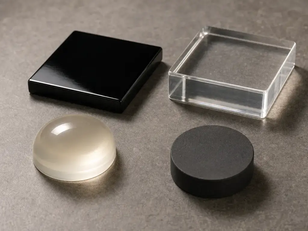
A reflective surface returns light directionally, so a scanner camera may see glare, reflections of the surroundings, or little usable signal as the viewing angle changes. A transparent surface transmits much of the projected or ambient light, so the observed response may come from a rear surface or background rather than the intended exterior.
A translucent surface admits light but scatters it internally, broadening or shifting the apparent pattern response. Dark or absorptive surfaces may return insufficient signal for reliable pattern detection, especially in deep concave regions where illumination and camera access are already limited.
Oily films add an uneven, mobile optical layer over the underlying material, so a nominally matte part can behave locally like a glossy one. In structured-light/triangulation work, NIST notes that concave geometry can be particularly challenging for deep, dark, and shiny features. [1] Black does not always mean unscannable, and transparency does not always require coating; results depend on the scanner, mode, geometry, illumination, and required output.
Technology and Mode Matter: Structured Light vs Laser-Line vs Photogrammetry
Structured light / full-field
Structured-light systems project a pattern and use active triangulation to calculate surface coordinates. Ambient illumination can reduce pattern contrast or saturate captured intensity, causing decoding errors, missing points, or erroneous coordinates. No reliable universal ambient-light threshold has been found because scanner design, material, geometry, and exposure settings vary. [1]
Laser-line modes
Laser-line capture remains an optical measurement method, so changing from full-field projection to a line does not remove surface-response problems. It can, however, change what is workable. Revopoint MetroX guidance distinguishes its Full Field and Auto Turntable modes from Cross and Parallel Lines modes for shiny black or metal objects. This is vendor- and mode-specific guidance, not a general rule. [9]
Photogrammetry (SfM/MVS)
Photogrammetry is not a scanner mode; it is an image-based workflow commonly using structure from motion and multi-view stereo. Transparent and specular objects remain difficult because their appearance changes with viewpoint instead of supplying stable image features. [15] A 2024 laboratory study used added granular texture and control points to obtain accurate, consistent SfM datasets from highly reflective surfaces. That is contextual evidence of the challenge, not a spray-free guarantee or a recommendation for improvised substitutes. [16]
3D Scanning Spray Alternative: A Decision Workflow
Use this sequence to make a defensible capture decision rather than treating a clean-looking mesh as proof of measurement quality. A single accuracy value cannot characterize structured-light performance across geometries and operating conditions, while ISO 10360-13 applies within cooperative surface characteristics. [1] [2]
- Define the output class: visual asset, fit-check model, reverse-engineering reference, or dimensional inspection result.
- Classify the surface: reflective, transparent, translucent, dark, oily, mixed, or geometrically inaccessible.
- Identify the sensing technology and operating mode.
- Apply non-coating controls first: stable fixturing, controlled illumination, appropriate angles, and available acquisition settings.
- Consider tracking aids separately from surface readability.
- Check raw capture before meshing for holes, noise, doubled edges, drifting features, and view-to-view inconsistency.
- Validate against the requirement using known features, a reference instrument, or a documented acceptance check.
- Consider a purpose-made temporary coating only when its use is justified by surface response and part constraints.
- Stop or change the method when confidence cannot be demonstrated.
Non-Spray Methods That Can Help — and Their Limits
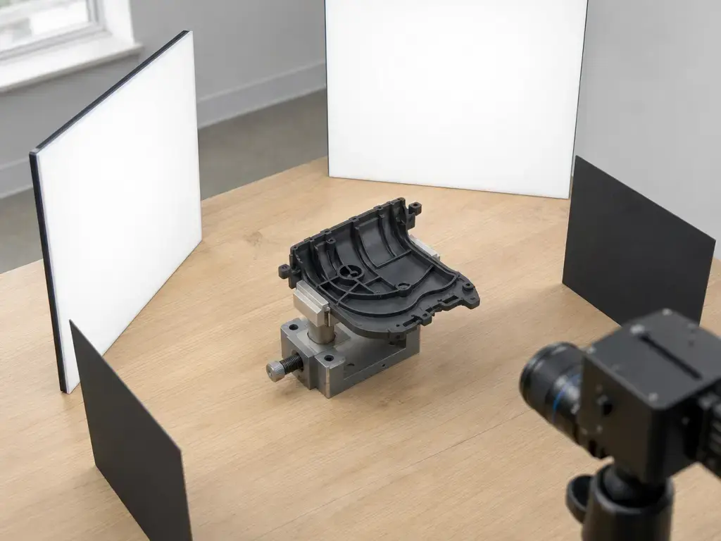
Non-coating controls should be tried before altering a part’s surface, provided they do not conflict with handling rules or the measurement requirement. In structured-light capture, controlling ambient illumination can improve pattern visibility, but no universal lighting setting applies to every scanner, material, geometry, or exposure configuration. [1]
| Method | May help with | Does not prove | Main caution |
|---|---|---|---|
| Controlled lighting | Stray-light contrast loss and glare management | Coordinate accuracy on difficult regions | Settings remain scanner- and surface-specific |
| Scan-angle changes | Directional reflections and occluded views | That returned light represents the intended surface | A new angle can move an artefact rather than remove it |
| Targets or background geometry | Registration and pose stability | Surface readability or dimensional validity | Targets can align poor data convincingly |
| Cleaning permitted films | Oily contamination and loose residues | That the underlying material is optically cooperative | Cleaning must be compatible with the part and process |
What these methods can solve — and what they cannot solve
- They can improve signal conditions, viewpoint coverage, and registration stability without adding a coating.
- They cannot turn transmitted light, severe absorption, or unstable reflections into verified surface coordinates.
- Tracking success ≠ valid surface data.
- They cannot replace an acceptance check on critical geometry.
Artec’s Sensitivity controls may help accommodate difficult capture conditions in applicable Artec workflows, but they do not establish a general spray-free rule. [5] If critical regions remain incomplete or unstable after permitted lighting, angle, fixturing, and cleaning changes, escalate to a documented coating or a different measurement method.
Tracking Aids Are Not Matting: Registration ≠ Surface Readability
Targets and markers provide reference locations for aligning successive views. Registration can therefore be stable while surface point positions remain wrong, sparse, or missing. Inspect the raw observations and reconstructed geometry in the regions that matter rather than relying on registration status alone.
This distinction is especially important on mixed-material objects. A fixture, label, or textured area may track well while clear, mirror-like, dark, or oily zones remain unreliable. SHINING 3D likewise presents marker use and spraying as separate preparation measures in its laser-scanning guidance. [7]
When a Coating Is Still the Better Option — and How to Choose the Least-Risky Type
Escalate to a coating when non-coating controls cannot demonstrate confidence in the required surface coordinates. Where powder spraying is explicitly specified in applicable technical documentation for ISO 10360-13 testing, it must be used during that test. [3] This does not make coating dimension-neutral: structured-light data processing and filtering can affect metrological results, so the changed surface remains part of the measurement condition. [1]
Washable/removable coatings require a cleaning or removal step after capture. Self-vanishing (“sublimating”) coatings are intended to disappear over time, but are not residue-proof. Persistent / cleaning-required coatings still need removal even if marketed as easy to remove. The least-risky choice has documented optical benefit, a defined removal process, and confirmed compatibility with the part and workflow.
Any coating can introduce geometry-dependent bias. External open surfaces may receive relatively even coverage, while holes, threads, sharp edges, mating faces, masked zones, and inaccessible recesses are more sensitive to uneven thickness and local surface orientation. AESUB gives a manufacturer-stated example of a 7 µm layer for AESUB White; its technical data sheet specifies a 15–20 cm application distance and notes that repeated spraying increases thickness. These are product-specific figures, not universal application or compensation values. [10] [11]
What Is Sublimating Scanning Spray? And What “Vanishes” Really Means
A sublimating scanning spray is intended to disappear over time under stated conditions while temporarily making a difficult surface more optically cooperative. “Vanishes” does not mean residue-free or dimension-neutral: the coating exists during capture and can alter the surface presented to the scanner.
A 2023 comparison of eight sublimation sprays found coatings in the order of tens of micrometres that were detectable with an ATOS III Triple Scan. All tested materials enabled capture of a highly reflective silicon-wafer surface, but results varied by product. Under the study conditions, one-layer disappearance ranges were no more than 90 minutes, 130–300 minutes, and 300–500 minutes for short-, middle-, and long-time groups. Visible traces remained on the mirror-like surface after apparent disappearance, although they could be wiped away in the study. [4]
Titanium Dioxide-Free Scanning Spray: What the Label Does and Does Not Mean
“Titanium dioxide-free” identifies an ingredient-related product attribute, not a blanket conclusion about safety, residue, compatibility, or measurement effect. The Court of Justice of the European Union upheld annulment of an EU harmonised carcinogenic-classification outcome concerning certain powder forms containing at least 1% particles with aerodynamic diameter at or below 10 µm. That legal outcome is not a product safety approval. [13]
Hazard communication remains formulation-specific. OSHA’s titanium dioxide chemical-data page presents OSHA permissible exposure limit and ACGIH threshold limit value information in separate columns from different issuers. [14] An AESUB White safety data sheet dated November 10, 2026 classifies the aerosol as Aerosol 1 with H222 and H229 and identifies it as hazardous under OSHA Hazard Communication Standard criteria. [12] Consult the current SDS for the exact product and your controls.
Measurement Risk — How to Verify an Alternative Worked
Validation is output-dependent
Acceptance criteria come from the job requirement. A visual model may need credible coverage, while an inspection result requires a traceable reference or independent reference measurement. Checking one feature does not validate the entire part; critical regions, materials, orientations, and feature types should represent the intended use.
| Output class | Minimum validation evidence | What it does not prove | Stop condition |
|---|---|---|---|
| Visual model | Review of coverage and visible artefacts | Dimensional accuracy | Critical appearance regions remain incomplete or implausible |
| Reverse-engineering reference | Comparison of selected functional geometry to a reference | Fitness for inspection | Key geometry cannot be located consistently |
| Fit-check | Comparison of relevant interfaces to known part features | Full-part conformance | Mating regions show unstable or missing data |
| Inspection result | Traceable reference or independent reference measurement | Validity beyond the tested requirement | Required features cannot be demonstrated against the reference |
Raw data → registration → fusion → meshing
Confidence can be lost at every stage after acquisition. ISO 10360-13 identifies software filters, registration, fusion, and pre-installed smoothing among manufacturer-rated operating-condition considerations. [3] In structured-light work, NIST reports that filtering and non-uniform point density can affect calculated flatness, sphere diameter, and form. [1]
Post-processing caution
A polished mesh can conceal acquisition failure rather than correct it. Revopoint cautions that smoothing and hole filling can hide gaps, round edges, or create geometry that was not captured. [17] Preserve raw captures, document processing steps, and stop when the evidence does not support the intended claim.
Suggested Capture Record: So Results Are Auditable Later
A concise record supports later review when a mesh looks plausible but its measurement basis is uncertain. Revopoint advises recording surface treatment for production or inspection work and checking for edge buildup that could alter dimensions. [17]
- Scanner model, software version, firmware version, and selected scan mode.
- Part material, finish, surface condition, and mixed-material regions.
- Ambient-light notes, including nearby reflective objects and light changes during capture.
- Distance, angle, and exposure settings as documented by the scanner; identify these as mode-specific rather than universal settings.
- Tracking method, target type, and whether tracking relied on the part, markers, or surrounding geometry.
- Surface-treatment product, formulation, lot number where available, and application timing.
- Raw captures retained, registration approach, and processing steps such as filtering, fusion, smoothing, or hole filling.
- Validation basis: nominal CAD vs calibrated artifact vs independent measurement.
Stop Conditions: When “No Spray” Means “No Scan”
Stop the spray-free attempt when critical areas remain unobserved, unstable between views, or unsupported by validation. Clear objects, mirror finishes, tolerance-critical geometry, and contamination-sensitive parts can exceed ordinary optical assumptions. Transparent and specular reconstruction remains a specialized, unresolved general problem in image-based reconstruction. [15]
When confidence cannot be demonstrated, change scanner technology, use a different metrology method, or state that the requirement cannot be demonstrated. Inability to scan uncoated is not permission to coat: handling restrictions, the measurement objective, and available validation evidence still govern the decision.
Conclusion: Choosing a 3D Scanning Spray Alternative
A 3d scanning spray alternative should follow a clear hierarchy: define the need, classify the surface, identify the mode, try non-coating controls, validate, use coating only if justified, and stop when confidence cannot be demonstrated. A usable-looking model is not the same as demonstrated reliability. ISO performance verification is framed around cooperative surfaces, so surface behaviour remains part of the measurement decision. [2]
When coating is justified, treat it as a temporary change to the measured surface rather than a neutral convenience. The sublimating-spray study found detectable coatings in the order of tens of micrometres under its test conditions. [4]
FAQ
What can I use as a 3d scanning spray alternative?
A 3d scanning spray alternative can include controlled lighting, changed scanner angles, an appropriate capture mode, stable fixturing, permitted cleaning of surface films, or a different sensing method. Targets can assist alignment, but they do not make a difficult surface readable. Choose the method only after defining whether the result is intended for appearance, reverse engineering, fit checking, or inspection.
How do you 3D scan reflective surfaces without spray?
Reduce stray illumination and scan from angles that avoid directing glare into the camera. Use the applicable scanner mode, keep the part stable, and inspect raw captures for holes, noise, doubled edges, and shifting features before meshing. Repeat views of critical regions and compare relevant features with a suitable reference. If reflections still produce unstable coordinates, an uncoated workflow has not been demonstrated.
What is sublimating scanning spray, and does it leave residue?
Sublimating scanning spray is intended to disappear over time under stated conditions, leaving a temporary matte optical surface during capture. That description does not establish residue-free or dimension-neutral behaviour. In a comparative study, visible traces remained on a mirror-like surface after apparent disappearance, although the traces could be wiped away under the study conditions. [4] Check the specific product documentation and inspect the part afterward.
Is titanium dioxide free scanning spray safe?
Titanium dioxide-free is not enough information; consult SDS for the exact formulation, part compatibility, and required controls. The CJEU outcome concerned a specific EU harmonised classification result for certain titanium-dioxide powder forms; it was not a product safety approval. [13] OSHA’s chemical-data presentation also distinguishes OSHA PEL and ACGIH TLV columns from different issuers. [14]
Can marker dots replace matting spray for 3D scanning?
No. Marker dots can provide reference positions that help software align separate views, but they do not alter how the scanner reads the surface between them. A scan may register consistently while reflective, clear, dark, or oily regions remain sparse, displaced, or missing. Use markers to support registration, then inspect and validate the actual part surface around critical features.
Expert: How can I validate a spray-free workflow for inspection without a traceable artifact?
No reliable figure found for universal acceptance thresholds because scanner, mode, geometry, material, and inspection requirement vary. Define the inspection requirement first, then perform repeatability checks across recaptures, viewpoints, and critical regions. Compare relevant features with an independent reference measurement and retain raw captures plus processing records. If neither a traceable artifact nor an independent reference can support the claim, state that the inspection requirement cannot be demonstrated.
Expert: How does coating thickness bias threads, holes, and mating faces compared with open surfaces?
Coating bias is geometry-dependent, so no universal offsets should be applied. On open external surfaces, a relatively uniform layer may shift the observed exterior in a predictable-looking direction. Holes, threads, sharp edges, and mating faces are more sensitive to uneven coverage, limited access, local surface orientation, and changing viewing angles. Detectable sublimating layers in the order of tens of micrometres have been reported. [4]
Sources
- NIST (2019). Sources of Errors in Structured Light 3D Scanners — scientific/government PDF.
- ISO (2021). ISO 10360-13:2021 — Optical 3D CMS — standard.
- ISO (2021). ISO 10360-13:2021(E) sample/preview PDF — standard.
- Franke & Koutecký et al. (2023). Comparison of Sublimation 3D Scanning Sprays in Terms of Their Effect on the Resulting 3D Scan, Thickness, and Sublimation Time — scientific paper.
- Artec 3D Support (updated August 2023). Scanning sprays — manufacturer documentation.
- Artec 3D Support (2020-03-19). Black, reflective, transparent, etc. surfaces — manufacturer documentation.
- SHINING 3D Support (modified 2025-02-14). Preparation for Laser Scanning — manufacturer documentation.
- SHINING 3D Docs (2025). OptimScan Q12 — Preparation — manufacturer documentation.
- Revopoint. MetroX Quick Start Guide — manufacturer PDF.
- AESUB (2026). Scanning sprays — manufacturer product page.