
Summary
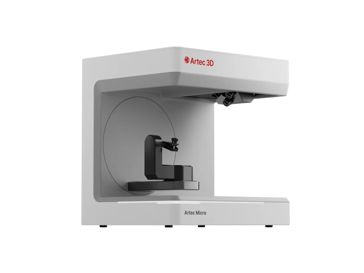
Artec Micro II is a desktop 3D scanner for small objects, not a handheld unit. Artec’s current public specs position it as a high-accuracy, mounted-object system with manufacturer-stated 3D point accuracy of up to 5 microns and 2-micron repeatability. [1] [2] If your work involves scanning small external parts inside a recommended 200 × 200 × 150 mm, 2 kg envelope, and you value bench automation, fixture-based repeatability, and an inspection or scan-to-CAD workflow, Artec Micro II is a strong candidate for the best 3D scanner for small objects in that narrow class. [1] [2] It is not automatically the best choice for budget buyers, portable field work, large parts, or jobs where hidden internal geometry matters, because those needs sit outside what a desktop optical surface scanner is designed to solve. [1] [2] [13]
How to judge “best” for small-object 3D scanners
The right question is not “what is the best desktop 3D scanner for small parts?” in the abstract, but best for which tolerance regime, surface condition, geometry, throughput target, software workflow, and budget. [13] A small polished turbine blade, a matte plastic connector, a jewelry master, and a dental model can all count as “small objects,” yet each stresses a scanner differently through reflectivity, occlusion, edge sharpness, and traceability needs. [5] [13] Judge fit by the dimensions you need to trust, how often you must repeat the job, whether the part can be rigidly fixtured, whether multiple flips and merges are acceptable, and whether the downstream goal is inspection, mesh editing, or scan-to-CAD reconstruction. [1] [5] [13]
Published specs are useful, but they are not a substitute for validation, verification, uncertainty budgeting, or acceptance testing on your own parts. [13] NIST warns that structured-light scanner performance depends on configuration, projected patterns, work volume, point density, triangulation angles, and target characteristics. A scanner specified under one test condition may not behave the same way in a different real-world application. [13]
Historical background: From Artec Micro (2019) to Artec Micro II (2023)
Artec announced the original Artec Micro on May 7, 2019, with a stated point accuracy of up to 10 microns. [8] The later Micro brochure describes that first-generation system as handling objects up to 90 × 60 × 60 mm, with stated 0.01 mm point accuracy and 0.029 mm resolution. That provides a useful baseline for how the product line started. [9]
Artec announced Micro II on November 7, 2023, and presented it as a step up in stated accuracy and object envelope. [10] In that launch material, Artec said Micro II offered 5-micron accuracy, repeatability differences of less than 2 microns, and support for objects up to 20 × 20 × 15 cm. [10]
What Artec Micro II is (and isn’t)
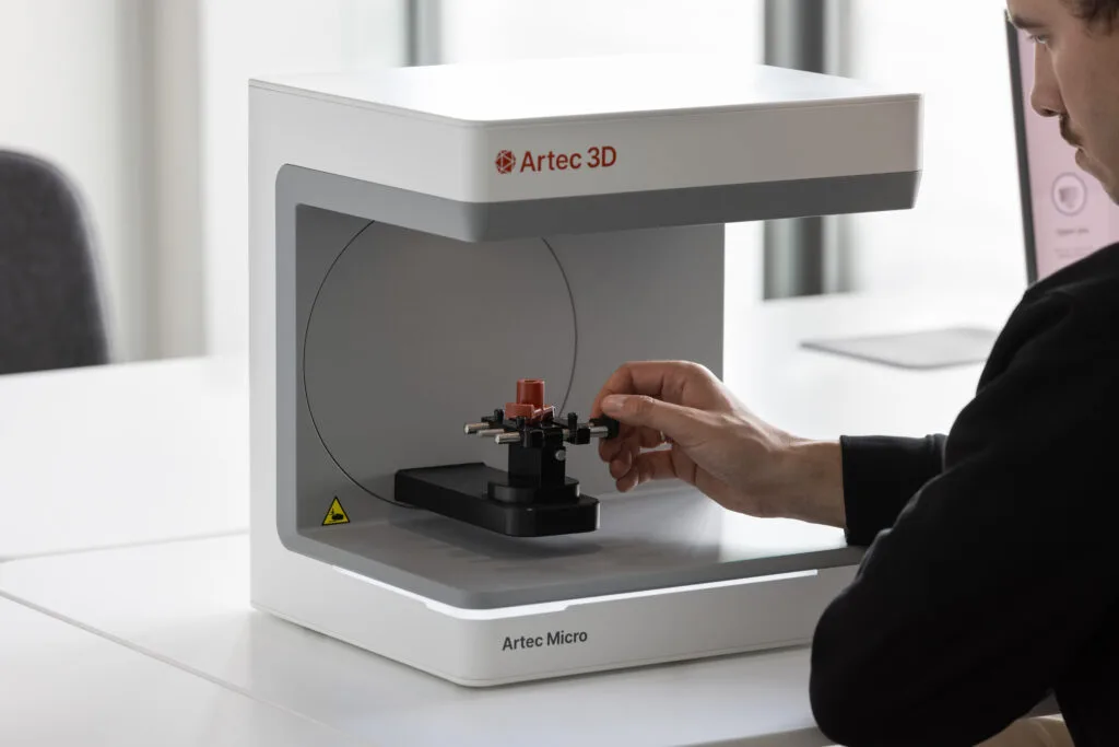
Artec Micro II is a desktop, mounted-object scanner. The object is fixed inside the machine, the stage rotates, and the scanner projects a white-light pattern while capturing the result with an RGB LED-based optical system. [1] [2] In practical terms, it is a structured-light desktop 3D scanner for small parts, not a handheld scanner and not a laser scanner. [1] [2] It is optimized for small external objects that fit within Artec’s recommended size range, not for large parts, hidden internal passages, or other jobs that require a different measurement modality. [1] [2] [13]
How structured-light desktop scanning works
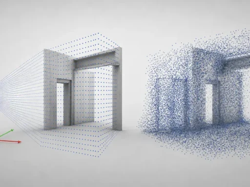
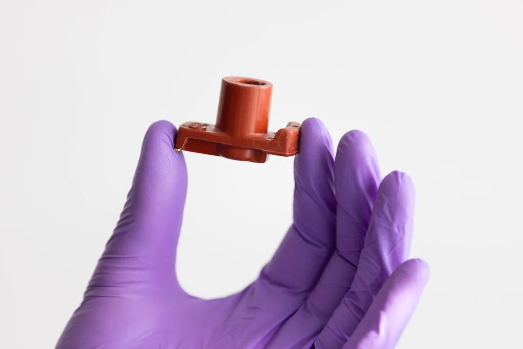
Micro II follows the usual structured-light logic in a more automated desktop package. [3] The scanner projects a light pattern onto the part, the surface distorts that pattern, and four high-resolution cameras record the distortion so the software can reconstruct the surface in 3D through optical triangulation. [3] [13] The result begins as 3D scan data that can be aligned, cleaned, fused, and turned into a mesh for inspection, comparison, or reverse-engineering work. [1] [3] Export options include common mesh formats plus CAD-related and measurement formats, but export compatibility is not the same thing as automatic parametric CAD reconstruction. [1]
Small objects are harder than they look because the details that matter are often the same ones most likely to cause trouble. [13] Sharp edges, recesses, shiny finishes, transparent areas, and hidden undersides increase the importance of scan planning, fixture design, and multi-orientation coverage. [5] [13]
Workflow & setup realities
A desktop scanner does not remove the need for measurement discipline. [3] [4] Artec recommends calibrating Micro II once weekly and again after transport or relocation. Its setup guidance also warns against vibration, direct sunlight, and rapidly changing light during scanning. [3] [4] Those details matter because repeatable optical data starts with a stable bench, stable lighting, and a scanner whose calibration state is under control. [3] [4]
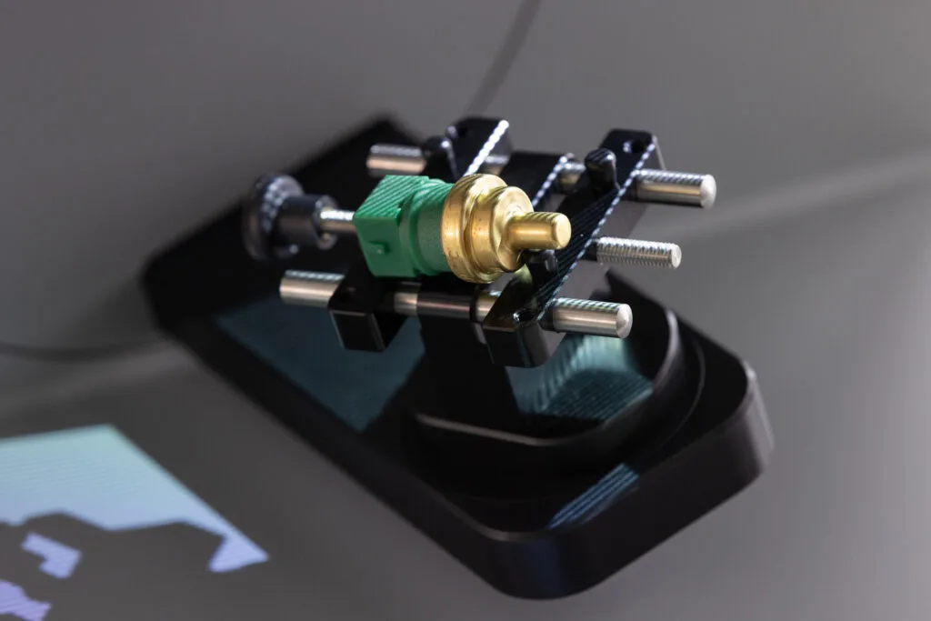
Fixturing and orientation strategy matter as much as headline specs. [5] The bottom side of a mounted part is always inaccessible in a single setup, so full coverage usually means flipping and rescanning, and complex objects may need more than two scans. [5] Artec’s optional 3-axis holder can help on complex objects about 2 to 9 cm wide, but it does not eliminate the need to plan for occlusion, common reference geometry, and alignment quality when scans are merged. [5]
- Prepare the surface, and use removable spray or talc when the part is too dark, shiny, or transparent to scan reliably. [5]
- Fixture the part rigidly and choose an orientation that minimizes hidden areas in the first scan. [4] [5]
- Calibrate, or at least verify that calibration is current, especially if the scanner was moved recently. [3]
- Choose an automatic, default, or custom path, and decide whether the optional 3-axis holder is needed. [5]
- Capture the first side, then review the result and add frames if necessary. [5]
- Flip or re-fixture the part to expose the underside and capture the additional scans needed for full coverage. [5]
- Align, merge, clean, and fuse the data, then export for inspection or scan-to-CAD work. [1] [5]
Key specs: and what they do not mean
Accuracy is about closeness to the true value, repeatability is about how consistently the system reproduces the same result, and resolution is about the fineness of captured detail or point spacing. [1] [13] Those terms are related, but they are not interchangeable. [13]
Artec’s headline number for Micro II is up to 5 microns 3D point accuracy. [1] That is a manufacturer-stated point metric, not a promise that every finished measurement on every finished part will land within ±5 µm after fixturing, flipping, alignment, merging, fusion, and downstream comparison. [1] [5] [13] Artec also lists ISO 12836 as the accuracy certificate, which is relevant because ISO 12836 covers mounted-object digitizing devices, but the public product and support pages do not publish a detailed artifact-by-artifact test method for the 5-micron value reviewed here. [1] [11] The sensible reading is that Micro II has a very strong manufacturer-stated point-accuracy claim for a desktop small-parts scanner, while task-specific dimensional trust still depends on the part, setup, and verification method. [1] [13]
The same caution applies to the 2-micron repeatability claim. [1] Artec frames repeatability as separate scans of the same object and notes that material and surface finish can slightly affect noise levels, so this is best understood as a controlled-condition repeatability statement, not a blanket guarantee for every multi-orientation job. [1] [2] If your part needs flipping, rescanning, and merging, the final whole-part result becomes more workflow-dependent. [5] [13] Likewise, the 40-micron resolution figure is not the same as minimum verifiable feature size, and Micro II’s recommended operating envelope of 200 × 200 × 150 mm and 2 kg says what size parts it is intended to handle, not what uncertainty every dimension will achieve. [1] [2] [13]
Specs snapshot (Micro II): quick reference table
For current buying decisions, the live product page and support documentation are the safest sources to prioritize. [1] [2] [6] That matters here because an older Micro II brochure shows a larger field-of-view-style figure and 6,000 cm³ capture volume, while the current live page lists Ø 20 × 15 cm and 4,700 cm³. The live page is the better buyer-facing reference. [1] [7]
| Spec | Value (manufacturer/official) |
|---|---|
| 3D point accuracy / repeatability | Up to 5 µm; 2 µm repeatability. [1] |
| Recommended object size / weight | Up to 200 × 200 × 150 mm; up to 2 kg. [2] |
| 3D resolution | 40 µm. [1] |
| Field of view / capture volume | Ø 20 × 15 cm; 4,700 cm³. [1] |
| Scan axes | 3-axis; third axis sold separately; 3-axis holder optional. [1] [5] |
| Data acquisition speed | 1 mln points/s. [1] |
| OS / hardware minimums | Windows 10/11; 32 GB RAM minimum, 64+ GB recommended; NVIDIA Turing or newer with 4 GB VRAM minimum and 8 GB recommended. [6] |
Field of view and capture volume are not the same as recommended object envelope, so those rows should not be read as interchangeable size limits. [1] [2]
Standards & verification context: how to think about “metrology-grade” claims
Artec lists ISO 12836 on the Micro II product page as its accuracy certificate. [1] ISO 12836:2015 is a dentistry standard for digitizing devices used in CAD/CAM systems for indirect dental restorations, and its abstract says the methods require the object to be mounted relative to the digitizing system and do not apply to handheld scanners. [11] That makes ISO 12836 relevant context for a desktop mounted-object scanner like Micro II, but it is not the same as a universal industrial claim about every inspection workflow, every material, or every dimensional characteristic you may care about. [1] [11] [13]
ISO 10360-13 is useful as broader optical-metrology context because it covers acceptance and reverification tests for optical 3D coordinate measuring systems and limits applicability to cooperative surface conditions. [12] VDI/VDE 2634 Part 2 is also useful documentary context because it addresses area-scanning triangulation systems and describes single-view procedures, not systems built by transforming multiple views through repositioning of the sensor or object. [14] Neither of those standards is presented in Artec’s public Micro II sources as a Micro II certification claim, and NIST’s warning still applies: named standards do not remove the need to validate performance on your actual parts and conditions. [12] [13] [14]
Applications: when Artec Micro II is strongest
Micro II is strongest when the part is small, externally visible, and worth the discipline of a mounted desktop workflow. [1] [2] That can make sense for reverse engineering legacy parts, connectors, watch-scale mechanisms, dental models or impressions, and inspection-oriented capture of small industrial components, especially when you want mesh output plus CAD-related or measurement exports in the same ecosystem. [1] What those exports provide is workflow compatibility, not automatic design-intent reconstruction. [1]
The scanner also fits some jewelry, cultural-heritage, and forensic documentation use cases where small-object detail matters and bench automation is useful. [1] [2] But the application label alone should not decide the purchase. [13] Regulated workflow compliance (medical/dental), evidentiary chain-of-custody (forensics), and formal inspection traceability requirements are application-specific and not established by the specs alone. [13]
Limitations & trade-offs: when Micro II is not the best
Micro II is not a magic box for every small part. [5] Artec’s own scanning guidance says black or very dark surfaces, shiny or reflective surfaces, transparent materials, and thin edges are difficult cases, and it suggests workarounds such as anti-glare spray, talcum powder, or added background geometry. [5] The underside of the part is always hidden in a single mounted orientation, so complete coverage usually requires flipping and rescanning, and complex geometry can push the workflow beyond two scans. [5] That means the final model depends not only on the scanner, but also on fixture stability, orientation choice, overlap between scans, and the quality of alignment and merge steps. [5] [13]
There is also a CAD boundary to keep in mind. [1] Micro II can export STEP, IGES, and X_T, but exportable CAD-related files are not the same as automatic parametric feature recognition or a finished editable design tree. [1] If you need internal geometry, hidden channels, or subsurface information, an external optical desktop scanner is the wrong tool class. [13]
Buying verdict: who should choose Artec Micro II?
Artec Micro II is a compelling answer to “is Artec Micro II the best 3D scanner for small objects?” only when your requirements are this specific: small external parts, meaningful demands on repeatability, rigid fixturing, tolerance-sensitive workflows, and a preference for automated desktop capture over handheld flexibility. [1] [2] [13] If that describes your work, and your parts fit the envelope, your surfaces are manageable, and your team will validate results on representative parts, Micro II sits near the top of the desktop small-parts category. [1] [2] [13] If your priorities are low price, portability, large objects, or hidden internal features, it is not the best fit, regardless of how impressive the headline 5 µm and 2 µm numbers look on paper. [1] [13]
FAQ
Is Artec Micro II the best 3D scanner for small objects?
Conditionally, yes. [1] [2] It is strongest when you need a desktop, fixture-based workflow for small external parts and you care about Artec’s manufacturer-stated 5 µm point accuracy and 2 µm repeatability. [1] It is not automatically best for budget, portability, larger parts, or internal geometry. [1] [13]
Is Artec Micro II a desktop 3D scanner?
Yes. [1] [2] Artec describes it as an automated desktop scanner in which the part is fixed inside the machine and scanned on a rotating setup using a projected white-light pattern. [1] [2] That is a different workflow from a handheld scanner moved around the object by hand. [2] [11]
What does 5-micron accuracy mean on Artec Micro II?
It means Artec publishes “up to 5 microns” as a 3D point-accuracy figure for the scanner. [1] It does not mean every finished dimension on every part will be accurate to ±5 µm after flipping, alignment, merging, and processing. [1] [5] [13] Artec publicly lists ISO 12836, but the reviewed public pages do not provide a detailed public test method for that 5 µm figure. [1] [11]
What does 2-micron repeatability mean for inspection workflows?
It means Artec states the scanner can generally reproduce separate scans of the same object within about 2 microns under suitable conditions. [1] [2] That is most useful as a controlled-condition repeatability indicator. [13] If your inspection workflow requires flipping the part, combining scans, or dealing with difficult surfaces, the final result becomes more dependent on fixturing, overlap, and merge quality. [2] [5] [13]
Can Artec Micro II scan shiny, black, or transparent objects?
Sometimes, but not reliably without preparation. [5] Artec’s guidance flags dark, reflective, transparent, and thin-edged objects as hard to scan optically, and recommends aids such as anti-glare spray, talcum powder, or added background geometry where appropriate. [5]
Do I need the optional 3-axis holder?
Not always. [5] Artec says the default 3-axis path is intended for complex objects about 2 to 9 cm wide that can be clamped off-center, and the 3-axis holder is an optional accessory rather than standard delivery. [5] It can improve access to awkward geometry, but it does not remove the need to flip parts for full underside coverage. [5]
Does Artec Micro II create CAD-ready models automatically?
Not in the parametric-CAD sense. [1] Micro II can export STEP, IGES, and X_T, along with many mesh and measurement formats, which is useful for downstream workflows. [1] But export availability does not mean the scanner automatically understands design intent, features, constraints, or a full editable CAD history. [1]
Related on 3D Mag
Sources
- Artec Micro II product/spec page. https://www.artec3d.com/portable-3d-scanners/artec-micro — accessed July 28, 2026. (artec3d.com)
- Artec Support: Micro II FAQs. https://support.artec3d.com/hc/en-us/articles/15917653083154-Artec-Micro-II-FAQs-Frequently-Asked-Questions — accessed July 28, 2026. (support.artec3d.com)
- Artec Micro II User Manual v2.1 (PDF). https://docs.artec3d.com/microII/User%20Manual/2.1%20Artec%20Micro%20II%20User%20Manual.pdf — accessed July 28, 2026. (docs.artec3d.com)
- Artec Micro II Quick Start Guide v1.4 (PDF). https://docs.artec3d.com/microII/Quick%20Start%20Guide/1.4%20Artec%20Micro%20II%20Quick%20Start%20Guide.pdf — accessed July 28, 2026. (docs.artec3d.com)
- Artec Studio 20 docs: Scanning. https://docs.artec3d.com/as/20/en/scan.html — accessed July 28, 2026. (docs.artec3d.com)
- Artec Support: Micro II System Requirements. https://support.artec3d.com/hc/en-us/articles/23027695299218-Artec-Micro-II-System-Requirements — accessed July 28, 2026. (support.artec3d.com)
- Artec Micro II brochure (PDF). https://cdn.artec3d.com/content-hub-files/artec-micro-ii-en-a4-web.pdf — accessed July 28, 2026. (cdn.artec3d.com)
- Artec press release: Artec Micro launch (2019-05-07). https://www.artec3d.com/news/artec-micro-release — accessed July 28, 2026. (artec3d.com)
- Artec Micro brochure (PDF). https://www.artec3d.com/files/pdf/Artec3D-Micro.pdf — accessed July 28, 2026. (artec3d.com)
- Artec news release (Spanish): Micro II release (2023-11-07). https://www.artec3d.com/es/news/artec-micro-II-released — accessed July 28, 2026. (artec3d.com)
- ISO 12836:2015 abstract page. https://www.iso.org/standard/68414.html — accessed July 28, 2026. (iso.org)
- ISO 10360-13:2021 abstract page. https://www.iso.org/standard/74957.html — accessed July 28, 2026. (iso.org)
- NIST publication page: Sources of Errors in Structured Light 3D Scanners. https://www.nist.gov/publications/sources-errors-structured-light-3d-scanners — accessed July 28, 2026. (nist.gov)
- DIN Media listing: VDI/VDE 2634 Blatt 2:2012-08. https://www.dinmedia.de/de/technische-regel/vdi-vde-2634-blatt-2/154896837 — accessed July 28, 2026. (dinmedia.de)
- SHINING 3D AutoScan Inspec2 product page. https://www.shining3d.com/metrology-solutions/high-precision-3d-inspection-system/autoscan-inspec2 — accessed July 28, 2026. (shining3d.com)
- SHINING 3D EinScan SE V2 product page. https://www.shining3d.com/professional-solutions/desktop-3d-scanner/einscan-se-v2 — accessed July 28, 2026. (shining3d.com)