
Summary
The Artec Micro II jewelry 3D scanner is a strong option for high-accuracy, mounted-object desktop workflows, but it is not a universal best. Its vendor-published 5 µm 3D point accuracy, 2 µm repeatability, and 40 µm 3D resolution matter most when a small part can be fixtured cleanly and scanned in multiple orientations. [1] [2]
The real decision comes down to seven factors: accuracy, repeatability, resolution and detail capture, surface prep, coverage and fixturing, workflow time, mesh-versus-CAD output, and total cost. For jewelry, those factors matter more than any single headline number because polished metal, translucent stones, undercuts, and holder occlusion can undermine an otherwise impressive spec sheet. In practice, Micro II makes the most sense for small rings, settings, medals, and inspection-oriented parts that fit its published 200 × 200 × 150 mm, 2 kg object limits and accept a turntable workflow. It makes less sense when the job is gemstone-heavy, no-spray, highly movable, or handheld-first. [1] [2] [13] [14] [21]
How we judge “best” for jewelry scanning (and why most tables mislead)
Here, “best” means the scanner most likely to produce usable jewelry data with the least friction for the intended workflow. That is a use-case decision, not a universal truth. A desktop scanner can be the best choice for ring scanning, setting inspection, or repeatable small-part capture, yet still be a poor fit for a stone-heavy piece that must be handled with minimal prep. Downstream intent matters too: reference geometry, inspection, reverse engineering, and direct design reuse are different tasks, even when they all begin with “scan the ring.” [1] [2] [20]
Comparison tables often mislead because they mix unlike metrics. One vendor publishes 3D point accuracy and repeatability separately, another publishes a plain “accuracy” number without method detail, another emphasizes resolution or point distance, and another uses mm/pix. Those are not interchangeable. ISO 12836 is a mounted-object dental digitizing-device test context and explicitly does not apply to handheld scanners, while VDI/VDE 2634 Part 2 is a broader area-scanning triangulation context with acceptance and reverification language for single-view optical systems. NIST adds an important warning: scanners may be evaluated under these frameworks, but real objects can differ enough from test conditions that a buyer still cannot rank tools safely by a single number alone. In short, there is no cross-brand numeric ranking without test-method context. [1] [10] [11] [12]
I use metrology-grade once and narrowly: only for a scanner whose maker publishes accuracy or repeatability figures and ties them to a stated certification or test context. That is stronger than vague “high precision” marketing, but it is still not the same as independent jewelry validation. Elsewhere, the safer wording is inspection-oriented or high-accuracy desktop. [1] [10] [11]
- If you need repeatable mounted-object scanning, prioritize a desktop system with published accuracy and repeatability.
- If you need awkward access or larger organic forms, prioritize a handheld workflow.
- If you need scan-to-CAD handoff, prioritize export and reconstruction support rather than one headline spec.
- If you need reflective-jewelry capture with minimal prep, prioritize surface behavior and practical setup over nominal resolution.
Why jewelry is hard to 3D scan (especially rings and stones)
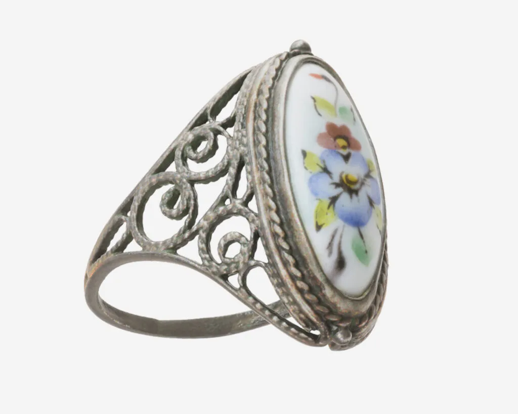
Jewelry is difficult because the features that matter most are often the ones optical systems struggle to see cleanly. Prongs, bead settings, engraved inner bands, filigree, stone seats, hollow backs, and undercuts all create line-of-sight problems. Even when a scan looks visually complete, it may still miss the exact geometry needed for resizing, repair, replication, or CAD rebuild work. With small objects, coverage is not just about whether something appears in the mesh, but whether the geometry is complete enough to trust. [14] [20] [21]
Reflective and high-dynamic-range surfaces add a second problem. Structured-light measurement can fail on shiny areas because low modulation and pixel oversaturation introduce phase-calculation errors, making accurate 3D data difficult to recover. Transparent and translucent stones are also hard cases for optical scanners, and the jewelry-specific proceedings in the source set support the broader point that small translucent gems are difficult to capture reliably. Spray is a common workaround because it reduces unwanted reflection and refraction, but it is not neutral. The spray study cited here found that both spray pass count and operator skill can significantly affect structured-light scanning performance, which means a sprayed scan is not automatically equivalent to an unsprayed measurement condition. [13] [14] [21]
The common failure points are familiar:
- prongs and bead settings
- engraved inner bands
- high-polish metal
- transparent or translucent stones
- chain links and movable assemblies
- hollow backs and undercuts
The practical takeaway is simple: the best jewelry 3D scanner depends heavily on whether prep and mounting are acceptable. [13] [14] [21]
Micro II for jewelry scanning: what it is in practical terms
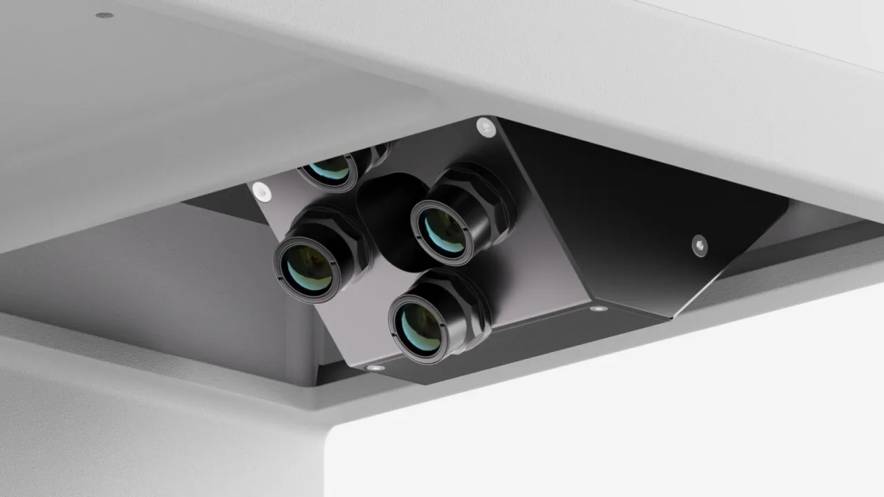
Artec Micro II is an automated desktop scanner for small objects, not a handheld scanner. Official documentation describes the object as fixed on a rotating table with fixtures while the scanner projects a white-light pattern, and the current product page publishes 5 µm 3D point accuracy, 2 µm repeatability, 40 µm 3D resolution, four 13 MP cameras, 1 mln points/s data acquisition speed, and a 3-axis scan system with the third axis sold separately. These are vendor-published or official workflow figures, not independent jewelry validation. [1] [2]
For buyer fit, the more practical numbers are the published object limits and capture envelope. The FAQ gives a maximum object weight of 2 kg and dimensions of 200 × 200 × 150 mm. The current product page lists a 4,700 cm³ capture volume and an Ø 20 × 15 cm field of view. An earlier brochure listed 6,000 cm³ and 20 × 20 × 15 cm, so the current product page is the better source for present-day envelope checks. In jewelry terms, that places Micro II in the controlled bench-tool category: strong when repeatable placement and fine detail matter, but still dependent on orientation, coverage, and post-processing. [1] [2] [3] [4]
How it works: structured light, blue light, and laser-based jewelry scanners
Micro II belongs to the projected-pattern optical scanner family. Official documentation says it projects a white-light pattern while the part sits fixed on a rotating table, and the product page lists RGB LED as the light source. In broader standards language, the relevant context is VDI/VDE 2634 Part 2, which covers optical 3D measuring systems based on area scanning and triangulation, using cameras and projection systems that place structures on the object surface. That matters because Micro II is not just a camera and not just a turntable. It is a geometric measurement system whose results depend on projector-camera geometry, surface behavior, and the chosen scanning path. [1] [2] [11]
Blue light is better treated as a light-source choice than as a guarantee of identical behavior across brands. SHINING 3D’s AutoScan Inspec2, for example, is published with LED blue light, 0.01 mm accuracy, 0.05 mm point distance, a 140 × 90 × 80 mm field of view, and a 3-axis rotation system. Those vendor-published numbers make it a relevant desktop comparison, but they do not mean every blue-light scanner behaves the same way on reflective jewelry or that blue light alone solves gemstone and polish problems. [18]
Laser-based jewelry scanners are another class again. Thunk3D markets the JS500 as a jewelry 3D laser scanner for 5–80 mm targets with 10 µm published accuracy and 0.06 mm resolution. The important point is not that laser automatically beats projected-pattern capture, but that “jewelry scanner” is a workflow category, not a single optical method. Surface response, object size, and budget still decide which class fits best. [17]
Accuracy, resolution, repeatability: what Artec’s “5 µm” does and doesn’t promise
Accuracy is closeness to a reference or true value. Repeatability is how consistently the scanner returns the same result when the same measurement is repeated under the same conditions. Resolution is about the smallest detail the system can meaningfully sample or separate in the result. In jewelry work, those three ideas answer different questions: dimensional trust, consistency across repeated jobs, and whether prongs, engravings, edges, and small seats survive capture and mesh generation with useful fidelity. [1]
Artec’s 5 µm figure is a vendor-published 3D point accuracy claim, paired with 2 µm repeatability and linked on the product page to ISO 12836. That matters, but it is not a blanket promise that a finished ring mesh will be within 5 µm everywhere. ISO 12836 is a mounted-object dental digitizing-device standard and explicitly excludes handheld scanners, so it is relevant as a class context for Micro II’s kind of setup, not as jewelry-specific proof. More importantly, a real jewelry scan still has to survive path selection, multiple orientations, alignment, fusion, and cleanup. NIST’s structured-light metrology discussion is useful here because it warns that evaluation frameworks do not automatically transfer cleanly to real objects that differ from the test conditions. [1] [10] [12]
The practical error sources are the ones jewelers already worry about: polished metal, translucent stones, spray, holder occlusion, and operator choices. The HDR structured-light review explains why shiny surfaces are so troublesome: low modulation and pixel oversaturation can produce phase-calculation errors. The coating-spray study adds another warning: spray may help a reflective or transparent part become scannable, but the number of spray passes and the skill of the operator can significantly affect structured-light measurement performance. That is why a spray-assisted scan may not preserve the same accuracy claim as a calibrated mounted-object test. The scan can still be useful, but it is no longer the same measurement condition. [13] [14]
So do not compare 5 µm, 10 µm, 0.01 mm, and mm/pix as if they were the same kind of claim. Without matching definitions, setup, and test method, they are orientation numbers, not a universal ranking. [1] [11] [12] [19]
Workflow in Artec Studio: from mounting to mesh export
The workflow starts with fixturing and surface policy, not software. You first decide whether the surface can stay untouched or whether scan spray is acceptable. On polished jewelry, that choice affects reflectivity, cleanup time, and whether the result is suitable for dimensional use or just reference geometry. Mounting matters too, because a holder can block the same prongs, seats, or inner-band details you want to preserve. Official documentation is useful here as workflow truth: brightness can be adjusted for visibility, and object stability matters because faster motion can shift or drop fragile parts. [4] [13]
Artec Studio then gives you path and settings choices that affect both coverage and output density. High Resolution mode generates four times more points than Standard mode, but at slower speed. “Enhance sharpness” is specifically noted as potentially poor on reflective surfaces, while “High precision mode” is aimed at metrological measurements with less focus on difficult surfaces. Micro II can also generate an Automatic path by analyzing the mounted object, and the docs define the default path families clearly: “Small” paths are for objects no bigger than 5 cm, while the optional 3-axis holder path is for objects 2–9 cm wide with more complex geometry. The main constraint never goes away: the bottom is inaccessible in one setup, so a second orientation is required for full coverage, and some objects need more than two scans. The scanner’s 1 mln points/s data-acquisition figure should also be read as throughput, not total job time. [1] [4]
A practical jewelry routine usually looks like this:
- Mount the ring or part securely on the fixture.
- Decide whether spray is acceptable for the job.
- Choose the path and settings, including resolution and precision options.
- Run the first scan and inspect coverage.
- Flip or reorient the part for hidden or bottom geometry.
- Align the scans, fuse them, and clean the mesh.
- Validate fit or measurements after any spray-assisted workflow before downstream use. [4] [13]
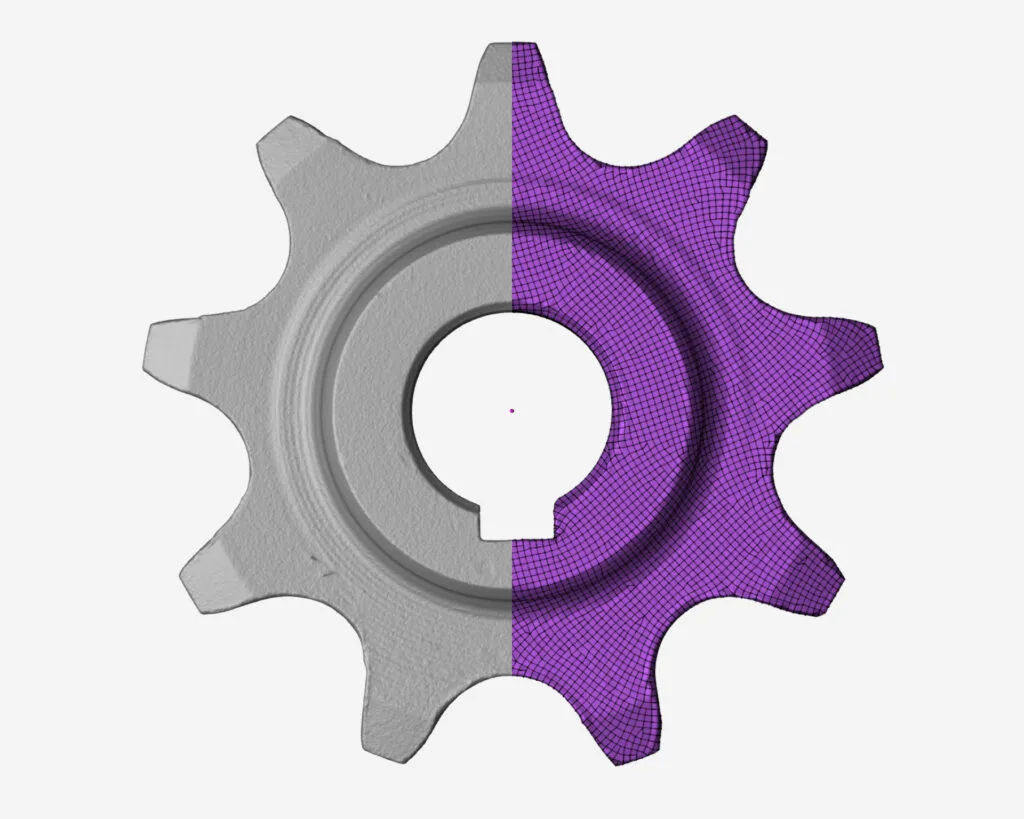
After alignment and fusion, the real work is usually cleanup and interpretation. Remove stray data, decide whether you need a watertight mesh, and check critical geometry before export. Micro II’s published output list includes mesh formats such as OBJ, PLY, WRL, and STL, plus CAD-labeled formats such as STEP, IGES, and X_T. That does not mean every jewelry scan exits the pipeline as a finished editable CAD part. It means the software can hand off polygonal data and certain CAD objects, with the reconstruction burden still depending on what you need next. [1] [9]
CAD-ready vs “exports STEP”: what you actually get out of the pipeline
A jewelry scan can be useful without being a CAD model. In practice, CAD-ready usually means the geometry is clean enough to measure, reference, or rebuild in design software, not that the scan is already a fully editable parametric solid. That distinction matters because mesh files describe surfaces with polygons, while jewelry CAD often needs curves, features, and repairable solids. eLUXE3D’s FAQ is unusually clear on this point: STL and OBJ are polygonal mesh files, not CAD models. [1] [16] [20]
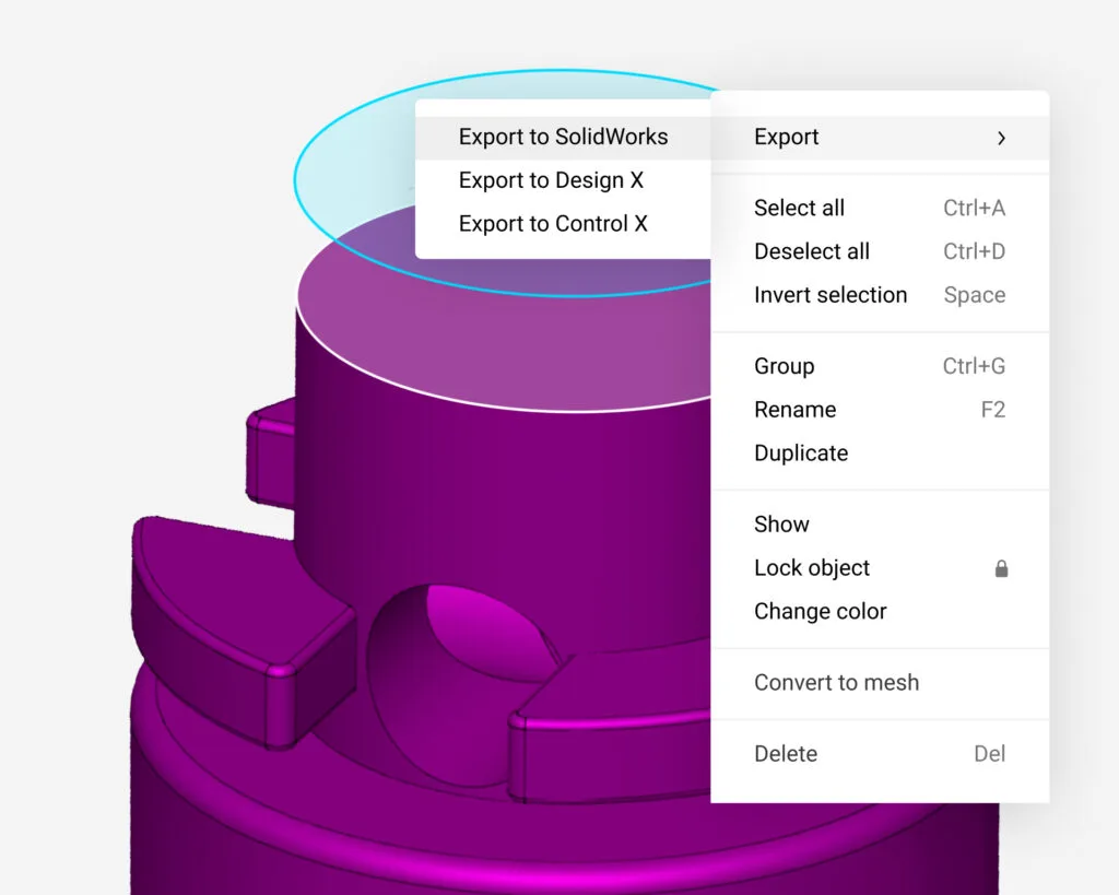
That is the key correction for Artec Studio’s STEP, IGES, and XT support. The product page lists those formats, but Artec’s own documentation says the software exports CAD primitives created in Artec Studio to STEP, IGES, and XT. That is not the same thing as automatic conversion of any arbitrary jewelry mesh into a clean parametric model. If your end goal is editable jewelry CAD, assume there may still be reverse-engineering or manual remodeling work after export. The scan can shorten that work substantially, but it rarely eliminates it. [1] [9] [16] [20]
Standards context: ISO 12836 vs VDI/VDE 2634
ISO 12836 matters here because it gives a formal accuracy-test context for mounted-object digitizing devices. The ISO catalog page identifies ISO 12836:2015 as Edition 2, published in July 2015, 19 pages long, and confirmed in 2020. More important than the dates is the scope: the test methods require the object to be mounted relative to the digitizing system and do not apply to handheld scanners. That makes the standard useful context for interpreting a scanner like Micro II, but it does not turn a dental test framework into jewelry-specific validation. [10]
VDI/VDE 2634 Part 2 is the broader optical-metrology context. The guideline covers area-scanning 3D measuring systems based on triangulation, including systems that use cameras plus projection techniques such as fringe projection or moiré, and it defines acceptance and reverification methods in a single-view context. NIST notes that some structured-light scanners are evaluated using VDI/VDE 2634 Parts 2 and/or 3. For buyers, the takeaway is modest but useful: these standards help explain the language around optical evaluation, yet they do not remove the practical jewelry questions about prep, mounting, occlusion, and multi-view stitching. [11] [12]
Comparison by class: published figures only, not normalized results
The table below groups scanners by job class rather than pretending they all solve the same problem. That is the only fair way to compare an automated desktop small-object scanner, a jewelry-focused desktop tool, a handheld detail scanner, and a page with incomplete metrology disclosure. The figures come from vendor pages or official product documentation, so they are useful for orientation, not for declaring a numeric winner. [1] [8] [15] [17] [18] [19]
Warning: the figures below are published vendor figures with different methods and definitions. They are not normalized results and they are not a ranking. [1] [10] [11] [12]
| Scanner (class) | Published accuracy / detail metric (as stated) | Scan area / capture envelope (as stated) | Best-fit jewelry role |
|---|---|---|---|
| Automated desktop (mounted / small-object / inspection-oriented) | |||
| Artec Micro II | 5 µm 3D point accuracy; 2 µm repeatability; 40 µm 3D resolution | FOV Ø 20 × 15 cm; volume capture 4,700 cm³; object up to 200 × 200 × 150 mm; 2 kg | Automated small-object capture where repeatability and inspection workflows matter. [1] [2] |
| SHINING 3D AutoScan Inspec2 | 0.01 mm accuracy; point distance 0.05 mm | FOV 140 × 90 × 80 mm | Automated inspection-oriented scanning for small parts; surface behavior on jewelry still needs workflow verification. [18] |
| Jewelry-specialist desktop (vendor jewelry workflow emphasis) | |||
| eLUXE3D Platinum | ≤10 µm accuracy; 0.024 mm resolution | 25 × 40 mm to 120 × 95 mm scanning area | Jewelry-focused scan-to-mesh workflow; published timing claims depend on prep and spray policy. [15] [16] |
| Thunk3D JS500 | 10 µm accuracy; 0.06 mm resolution | 5–80 mm targets | Dedicated small-jewelry laser option where the target size and workflow fit the job. [17] |
| Handheld detail capture | |||
| Artec Spider II | up to 0.05 mm accuracy; up to 0.05 mm resolution | 128 × 104 mm / 171 × 152 mm field of view | Handheld capture for organic forms, awkward access, and reference scanning where fixturing is less practical. [8] |
| Incomplete published metrology (treat with caution) | |||
| MicroForm3D | 0.029–0.035 mm/pix resolution metric | Work area 125 × 85 mm or 200 × 100 mm | High-detail scanning where pixel resolution is emphasized; no directly comparable 3D point accuracy disclosure by tier. [19] |
For jewelry users, the table says three things at once. First, Micro II sits in the fixed desktop lane, where repeatability, controlled orientation, and inspection-style use matter more than portability. Second, eLUXE3D and Thunk3D are more obviously targeted at jewelry-specific object sizes and bench workflows, but their output is still fundamentally scan-to-mesh first. Third, Spider II is the flexible handheld option when the object or working style resists a fixture-first routine. [1] [8] [15] [16] [17]
MicroForm3D is useful mostly as a cautionary example. The page emphasizes mm/pix resolution and tiered work areas, and it also uses generic marketing accuracy language, but it does not provide a clean, apples-to-apples disclosure that matches Artec’s 3D point accuracy plus repeatability structure. That does not make it unusable. It just means the published metrology is harder to compare responsibly. [19]
Where Micro II makes sense (jewelry applications)
Micro II makes the most sense when the jewelry is small, mountable, and worth reconstructing from controlled scan data rather than from photos or hand measurements alone. Independent reverse-engineering literature supports scan-based jewelry modification workflows, and that matters because the real goal is often redesign, restoration, or inspection rather than visual display. The same literature also shows the familiar pattern: higher-quality scanning helps, but the model still needs editing and downstream CAD work. That makes Micro II strongest as a geometry-acquisition tool inside a broader jewelry workflow, not as a magic button that ends the process. [1] [20]
The Cooksongold case study is useful only as workflow context, not as Micro II validation, because it used Artec Micro I. Even there, the lesson is realistic: scan-assisted work can reduce manual modeling time, but it still depends on export, editing, and designer judgment. For hobby cataloging, very large display pieces, or strict no-prep/no-handling constraints, Micro II can be more scanner than you need or the wrong class altogether. [7] [20]
Typical good-fit applications include:
- ring replication or resizing reference
- custom-fit bands
- restoration
- signets and medals
- stone-seat or setting geometry reference
- cast-part inspection
- inventory or insurance archiving
Limitations: when the “best” may be something else
Shiny metals, gemstones, dark materials, and mixed-finish jewelry all push projected-pattern optical capture toward its limits. Spray can help, but it is not a neutral fix. The scientific sources here support two important cautions: shiny surfaces can trigger low-modulation and oversaturation errors, and spray technique itself can alter results because pass count and operator skill matter. For gemstones, especially translucent ones, there is no reliable universal accuracy figure in the supplied sources that should be generalized. If gemstone reliability is the deciding factor, you need workflow testing on your actual parts, not a brochure number. [13] [14] [21]
The geometry limits are just as real. The bottom is inaccessible in one setup, so flipping is mandatory for full capture, and some parts need more than two scans. Chains, hinged pieces, and very open undercuts add handling complexity because the scanner can only see what the fixture does not hide. Even ring-shaped pieces may need a different path strategy or more manual intervention than the phrase “automated desktop scanner” suggests. [4]
There is also the cost and workstation side. As a US price snapshot dated July 27, 2026, Artec lists Micro II at US $24,240, the Micro II Premium Pack at US $32,940, Artec Studio Pro Subscription at US $1,700, and Artec Studio Pro Lifetime at US $4,300. The product page lists a 396 × 405 × 337 mm desktop footprint, 12 kg weight, USB 3.0 connectivity, Windows 10 (x64) and Windows 11 support, 32 GB minimum RAM, 64+ GB recommended RAM, 2 GB minimum VRAM, and a recommended NVIDIA GPU with at least 3 GB VRAM and CUDA 3.5+. That is a serious bench setup, not an impulse purchase or lightweight side tool. [1] [5]
Verdict: is it the best jewelry 3D scanner?
The Artec Micro II jewelry 3D scanner is one of the stronger options for high-accuracy desktop jewelry capture when the workflow is mounted, multi-orientation, and comfortable with scan-to-mesh or scan-to-CAD reconstruction. Its vendor-published 5 µm 3D point accuracy and 2 µm repeatability make it credible for repeatable small-part work. But the verdict is conditional: if your pieces are reflective, gemstone-heavy, hard to fixture, or expected to become editable CAD with almost no rebuild, this is not automatically the best fit. [1] [2] [9] [13] [21]
If your priority is a jewelry-centered desktop workflow, eLUXE3D may fit better by scan area and usage framing, while still remaining mesh-first. If you want a dedicated small-jewelry laser option, Thunk3D JS500 is the clearer comparison. If your priority is automated desktop inspection-style capture, AutoScan Inspec2 is the more direct alternative. If your priority is flexibility, awkward access, or organic capture, Spider II is the stronger handheld route. Artec’s own jewelry page also frames Micro II as the desktop option and Spider II or Eva as the more flexible handheld family choices. At the official US price snapshot of US $24,240 on July 27, 2026, Micro II sits firmly in premium territory, so it makes the most sense when the workflow savings and repeatability justify the cost. [5] [6] [8] [16] [17] [18]
FAQ
1. Is Artec Micro II good for jewelry scanning?
Yes, if the jewelry is small, mountable, and compatible with a turntable workflow that includes flipping, alignment, and cleanup. It is less compelling for highly reflective or gemstone-heavy pieces that you need to capture with little or no surface prep. [1] [2] [13] [21]
2. What does “5 µm 3D point accuracy” actually mean for a real ring (after alignment and fusion)?
It is a vendor-published point metric, not a guarantee on the final ring mesh. Once you add multiple orientations, alignment, fusion, and cleanup, total part deviation can exceed the headline point number. [1] [10] [12]
3. Can Artec Micro II scan gemstones reliably?
Not as a universal promise. Translucent and reflective stones are among the hardest cases for optical scanners, and no reliable universal gemstone accuracy figure is established in the sources used here. [14] [21]
4. What scanner specs matter most for jewelry: accuracy, resolution, or repeatability?
All three matter, but they answer different questions. Accuracy is closeness to reference, repeatability is consistency across repeated scans, and resolution is about how much small detail survives capture and mesh generation. In jewelry, surface condition and fixturing can matter just as much as the headline metric. [1] [13] [14]
5. Does Artec Micro II export CAD files (STEP/IGES/XT), and is that the same as “CAD-ready”?
It can export STEP, IGES, and XT, but Artec’s documentation frames that as CAD primitives export. That is not the same as automatic parametric reconstruction of any scanned jewelry mesh. [1] [9]
6. Is Artec Micro II better than eLUXE3D for jewelry?
Not in every workflow. Micro II is stronger when you want repeatable mounted-object desktop capture and inspection-oriented use, while eLUXE3D is more jewelry-specific in scan area and workflow framing. Both still lead to mesh-first outputs rather than instant editable CAD. [1] [15] [16]
7. Do I need scan spray for jewelry, and can it change measurement results?
Sometimes yes, especially on polished or translucent parts, and yes, it can change results. The spray study cited here found that both spray pass count and operator skill can significantly affect structured-light scanning performance, so measurement-sensitive jobs should be validated after prep. [13]
Related on 3D Mag
- Artec Micro II vs Artec Point for Jewelry
- Exploring the Different Types of 3D Scanners
- Metrology-Grade Scanner: High Accuracy 3D Scan
- Artec Point for Scanning Jewelry: Is It Worth It?
Sources
- Artec Micro II product page — https://www.artec3d.com/portable-3d-scanners/artec-micro
- Artec Support: Micro II FAQs — https://support.artec3d.com/hc/en-us/articles/15917653083154-Artec-Micro-II-FAQs-Frequently-Asked-Questions
- Artec Micro II brochure (PDF) — https://cdn.artec3d.com/content-hub-files/artec-micro-ii-en-a4-web.pdf#page=4
- Artec Studio 20 docs: Scanning — https://docs.artec3d.com/as/20/en/scan.html
- Artec official prices — https://www.artec3d.com/prices
- Artec jewelry solutions page — https://www.artec3d.com/3d-scanning-solutions/jewelry
- Artec case study: Cooksongold jewelry — https://www.artec3d.com/cases/cooksongold-jewelry
- Artec Spider II product page — https://www.artec3d.com/portable-3d-scanners/artec-spider
- Artec Studio docs: Projects and CAD import/export — https://docs.artec3d.com/as/17/en/projects.html
- ISO 12836:2015 catalog page — https://www.iso.org/standard/68414.html
- VDI/VDE 2634 Part 2 contents and scope PDF — https://www.vdi.de/fileadmin/pages/vdi_de/redakteure/richtlinien/inhaltsverzeichnisse/1907673.pdf
- NIST: Sources of Errors in Structured Light 3D Scanners — https://www.nist.gov/publications/sources-errors-structured-light-3d-scanners
- Yang et al. 2019: Influence of coating spray on surface measurement using 3D optical scanners — https://experts.illinois.edu/en/publications/influence-of-coating-spray-on-surface-measurement-using-3d-optica/
- Zhang et al. 2021: HDR structured light review — https://www.sciopen.com/article/10.51393/j.jamst.2021004
- eLUXE3D Platinum specs page — https://eluxe3d.com/
- eLUXE3D FAQ — https://eluxe3d.com/faq/
- Thunk3D jewelry scanners page — https://www.thunk3d-global.com/jewelry-3d-scanners
- SHINING 3D AutoScan Inspec2 — https://www.shining3d.com/metrology-solutions/high-precision-3d-inspection-system/autoscan-inspec2
- MicroForm3D product page — https://www.microform3d.com/
- Kroma et al. 2020 reverse engineering jewelry paper — https://www.astrj.com/pdf-128006-57163?filename=Modern-Reverse-Engineerin.pdf
- Patzlaff 2021 proceedings on gems and structured light — https://www.proceedings.blucher.com.br/article-details/digitalizao-3d-aplicada-ao-setor-de-gemas-e-joalheiro-pedrista-36823