
Summary
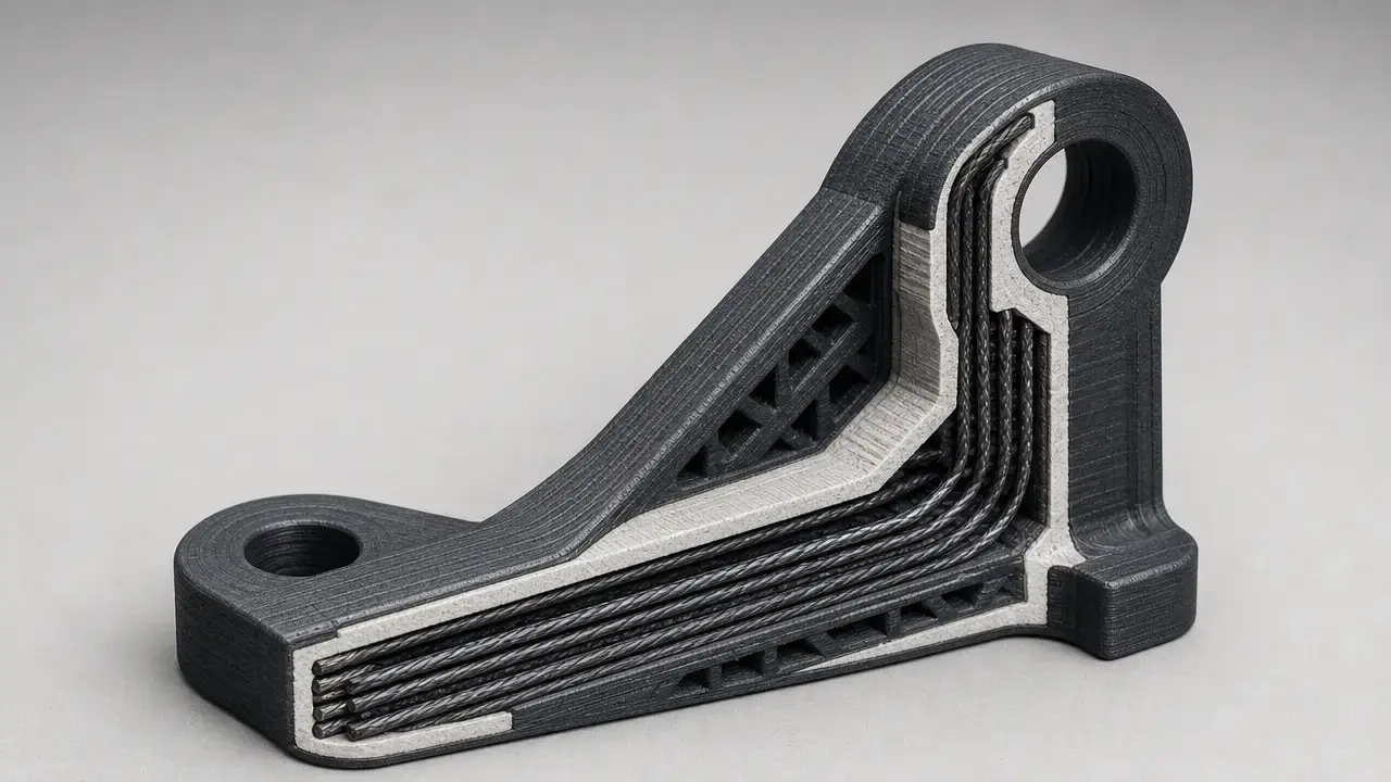
Continuous fiber 3d printing embeds long, uninterrupted reinforcement inside a polymer matrix during additive manufacturing. [1] Instead of treating fiber as chopped filler, it routes reinforcement along planned load paths, so the resulting mechanical properties depend on fiber orientation, bonding quality, voids, and print architecture. [8] [19] ISO/ASTM 52900 provides the generic vocabulary, and recent review literature treats anisotropy as a central engineering feature rather than a side note. [1] [19] In a published basalt-reinforced PA12 study, longitudinal and transverse properties differed sharply, underscoring that printed continuous-fiber parts should be evaluated as direction-dependent composites rather than uniformly stronger plastics. [16]
What Is Continuous Fiber 3D Printing?
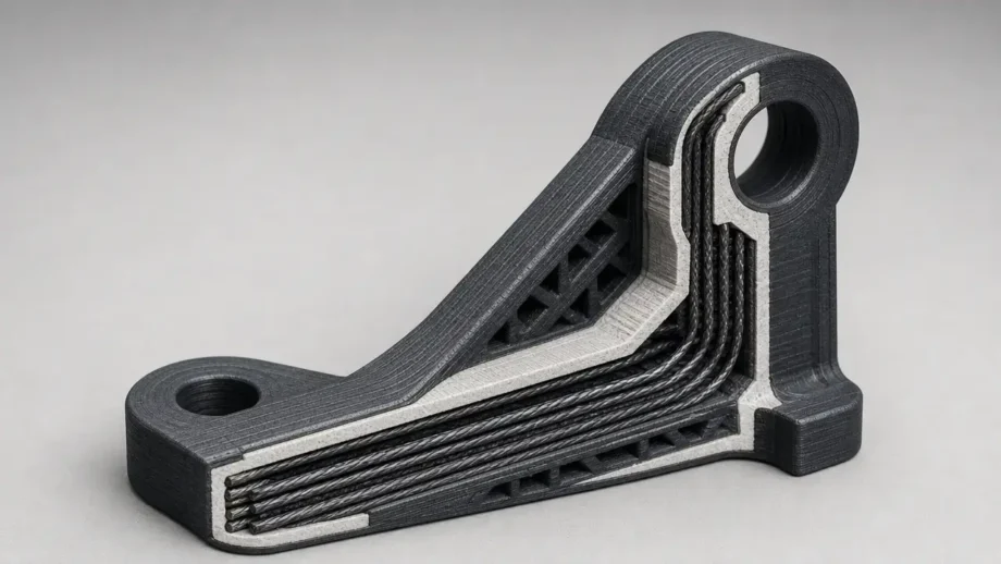
Continuous fiber 3D printing is not the same as carbon-fiber-filled filament. [1] Chopped-fiber filament can increase stiffness or reduce warpage, but its short fibers do not create an uninterrupted load path. [1] [8] Continuous reinforcement keeps the strand intact so it can carry load along selected toolpaths. [8]
It also helps to separate generic process language from vendor branding. [1] ISO/ASTM 52900 supplies additive manufacturing vocabulary, and ISO/ASTM 52903-1 frames feedstocks for plastic material-extrusion systems. [1] [2] In that standards language, material extrusion is the broad category; FFF and FDM are common industry labels for related deposition workflows, while names such as CFF or CFR describe particular implementations rather than the generic process family. [1] [8] In many commercial systems, the fiber is embedded inside a printed matrix part rather than printed alone, though the broader field also includes non-thermoplastic variants discussed later. [8] Continuous fiber reinforcement 3D printing is therefore best understood as composite deposition with controlled reinforcement paths, not ordinary plastic printing with a stronger filler. [1] [8]
- matrix material
- continuous reinforcement
- print path / fiber orientation
- consolidation or bonding mechanism
Historical Background: From Composite Layups to Continuous Fiber Additive Manufacturing
Before continuous fiber additive manufacturing, structural polymer composites were usually made by prepreg layup or dry-fiber layup into molds, followed by curing, autoclave or press consolidation, or more automated methods such as automated fiber placement and filament winding. [19] [20] Those methods remain important because they can deliver high fiber fractions and repeatable laminates, but they also depend on tooling, fixtures, and process planning that are less flexible than digital toolpaths. [20] [21] Continuous fiber AM emerged as a complementary route that places reinforcement where the load path needs it while reducing some tooling dependence. [19] [21] Reviews treat it as an extension of composite design freedom, not a blanket replacement for conventional laminates. [19] [20] Historical examples such as Desktop Metal Fiber and Arevo fit that transition and are best treated as contextual references rather than current buying guidance, especially because Stratasys announced the acquisition of Arevo’s technology portfolio on March 4, 2024. [13] [24]
Technical Principles: Matrix, Fiber, and Load Paths
In continuous-fiber composites, the fiber is the main axial load-bearing element along its length, while the polymer matrix stabilizes shape, protects the reinforcement, and transfers stress between adjacent fibers and layers. [16] [19] That is why a reinforced polymer part cannot be judged only by resin choice or only by fiber choice. [19] [20]
Load paths and fiber orientation control most of the benefit. [19] If the toolpath aligns with the dominant tensile or bending loads, continuous reinforcement can raise stiffness and strength dramatically in that direction. [16] [19] If the load crosses the fiber path or goes through thickness, the benefit falls quickly. [16] A 2024 basalt-reinforced PA12 study reported longitudinal tensile strength of 222.27 MPa versus 12.32 MPa transverse, and longitudinal modulus of 17.96 GPa versus 1.43 GPa transverse, with an effective basalt fiber volume fraction of 18%. [16] A separate optimization study found fiber angle contributed 54.13% to the grey relational grade, reinforcing how strongly orientation can dominate the result. [18]
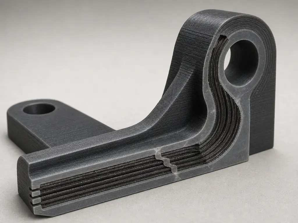
Strength and stiffness are different properties. [19] Tensile modulus describes resistance to elastic deformation, while tensile strength describes the stress at failure. [3] [19] A part can become stiffer without becoming equally resistant to cracking, splitting, or interlaminar damage. [19] In real printed parts, failure often begins at fiber-matrix interfaces, between layers, or in shear-dominated regions where the matrix must transfer load across neighboring beads or plies. [17] [19] Research on fiber-reinforced material extrusion links poor interfaces and measurable voids to lower mechanical properties, with review evidence citing void content up to 12% in printed CF/PA6 composites. [17] Coupon data are useful, but only when read as architecture-specific results rather than universal material constants. [19] [20]
How Does Continuous Fiber Reinforcement 3D Printing Work?
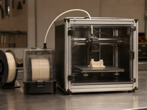
How does continuous fiber reinforcement 3D printing work in practice? [8] In a common thermoplastic architecture, one deposition system prints the base polymer and a second system lays continuous fiber inside selected regions or layers. [8] Markforged’s composites documentation says the fiber is placed through a second nozzle and cannot be printed by itself. [8] Anisoprint-style co-extrusion combines matrix and reinforcement differently, while Continuous Composites’ CF3D uses robotic deposition and real-time UV curing instead of standard thermoplastic FFF. [11] [15]
The key decision is where the fiber should go and whether the added reinforcement is worth the path-planning constraints. [18] Along-path properties in Anisoprint’s data sheet underline that the direction of measurement is part of the result. [11] In one optimization study, the reported optimum used 80% infill, 0° fiber angle, carbon-fiber layer position 12–13, and 10 mm/min strain rate, and fiber angle contributed 54.13% to the grey relational grade. [18] In practice, the workflow is a sequence of design, routing, printing, and verification steps rather than a single material choice. [8] [23]
- Import CAD model.
- Select matrix and fiber.
- Orient the part for load and printability.
- Place fiber along load paths or selected layers.
- Print matrix and reinforcement.
- Inspect, test, or qualify for the application.
Types of Continuous Fiber Additive Manufacturing
Continuous fiber additive manufacturing is not one machine category. [20] The family includes nozzle-based thermoplastic systems, co-extrusion approaches, narrow-tape placement, and robotic resin-cure processes. [13] [14] [15] What ties them together is long-fiber continuity; what separates them is how the fiber is fed, constrained, wetted or pre-impregnated, and consolidated into the growing part. [14] [15] [20]
| Process family | Matrix / feedstock | Fiber placement concept | Notes |
|---|---|---|---|
| Dual-nozzle FFF/CFF | Thermoplastic base filament | Secondary nozzle lays continuous fiber in selected layers | Markforged-style example |
| Composite fiber co-extrusion | Thermoplastic plus pre-impregnated composite fiber | Fiber and matrix co-extruded or bonded during deposition | Anisoprint-style example |
| Micro automated fiber placement | Thermoplastic tape / prepreg-style format | Narrow continuous fiber tape placed by compaction head | Desktop Metal Fiber as historical example |
| Robotic thermoset CF3D | UV-curable thermoset resin | Fiber tow deposited and cured in real time | Continuous Composites example |
Desktop Metal Fiber and Arevo are historical or contextual references here, not current buying recommendations unless current availability is separately verified. [13] [24]
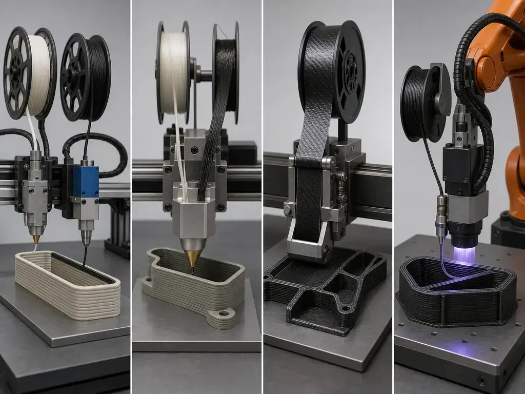
The table is best read as a deposition-method taxonomy, not a brand ranking. [20] Markforged-style CFF systems represent a nozzle-based inlay approach within thermoplastic printing. [8] Anisoprint-style co-extrusion stays in the thermoplastic family but changes how reinforcement and matrix are combined. [11] Desktop Metal’s historical Fiber platform illustrates a μAFP branch, using 3 mm tape, up to 12K tows, and historical claims of up to 60% fiber volume fraction. [14] Continuous Composites’ CF3D sits in a different family because it steers fiber robotically and cures a resin system in real time with UV light. [15]
What Materials Are Used in Continuous Carbon Fiber 3D Printing?
Material choice in continuous carbon fiber 3D printing is always a matrix-plus-reinforcement question, not a fiber-only question. [8] [11] Published vendor and research data show that both the fiber class and the deposition architecture shape the final result. [11] [19]
Documented commercial examples
Commercial documentation covers more than continuous carbon fiber alone. [8] Markforged documents continuous carbon fiber, fiberglass, aramid fiber (Kevlar-type), and HSHT fiberglass as reinforcement options for composite base materials such as Onyx, a micro-carbon-fiber-filled nylon. [8] In Markforged’s manufacturer data, Onyx is listed at 2.4 GPa tensile modulus, 40 MPa tensile stress at yield, 71 MPa flexural strength, 145 °C heat deflection temperature, and 1.2 g/cm³ density. [8] The same manufacturer data list its continuous carbon-fiber composite plaque at 800 MPa tensile strength, 60 GPa tensile modulus, 420 MPa compressive strength, 540 MPa flexural strength, and 51 GPa flexural modulus. [8] Markforged also notes that its fiber composite test plaques were fully filled, unidirectional 0° specimens, so those figures are manufacturer coupon data, not generic part properties. [8] Anisoprint documents PETG plus continuous carbon fiber at 774.4 ± 27.1 MPa tensile strength, 56.6 ± 0.4 GPa tensile modulus, 1.3 ± 0.02% tensile strain at break, and 1.4 g/cm³ density along printing paths. [11] [12] The same data sheet lists PETG plus continuous basalt fiber at 604.1 ± 16.9 MPa tensile strength and 22.6 ± 0.3 GPa tensile modulus, showing that continuous reinforcement is not limited to carbon fiber. [11]
Platform-specific matrix and fiber classes
That variety should not be mistaken for universal compatibility. [19] Some commercial systems center on nylon or other polyamide-derived base materials, others on PETG-based co-extrusion, and robotic thermoset systems form another branch altogether. [8] [11] [15] Carbon fiber is the best-known reinforcement, but glass or fiberglass, aramid/Kevlar-type fiber, and basalt are all documented in the source pool. [8] [11] What materials are used in continuous carbon fiber 3d printing therefore depends on the validated feedstock list for a specific machine, nozzle architecture, and consolidation method. [8] [11] For high-temperature matrices such as PEEK, PEKK, or PEI/ULTEM-class polymers, no reliable figure was found in the source pool for a broad, cross-platform compatibility claim that would be safe to generalize here. [10] [15] [22] Continuous Composites confirms the thermoset CF3D family on its official technology page, but no reliable universal performance figure is provided there for direct comparison with thermoplastic vendor coupons. [15]
Performance Metrics: Strength, Stiffness, Anisotropy, and Standards
Mechanical properties in this category need to be read as a set, not as a single headline number. [19] Tensile strength, tensile modulus, flexural strength, compressive strength, density, and void content answer different questions. [3] [4] [6] [17] Markforged’s manufacturer data, for example, list Onyx at 2.4 GPa tensile modulus and 40 MPa tensile yield, while the same source lists its continuous carbon-fiber plaque at 800 MPa tensile strength, 60 GPa tensile modulus, 420 MPa compressive strength, and 540 MPa flexural strength. [8] Anisoprint lists 1.4 g/cm³ density for its PETG plus continuous carbon fiber material measured along printing paths. [11]
Standards matter because composite coupons and plastic specimens are not interchangeable evidence. [3] ASTM D3039/D3039M is the main in-plane tensile coupon standard for polymer matrix composites reinforced with high-modulus fibers. [3] ASTM D6641/D6641M-23 covers compression using a combined loading compression fixture. [6] ASTM D638 is the tensile standard for plastics. [5] ASTM D790-25 covers flexural properties, but it notes that flexural strength cannot be determined for materials that do not break or yield at the outer surface within the 5.0% strain limit. [4] That distinction matters because base-plastic numbers and continuous-fiber composite numbers are often produced by different specimen geometries and failure assumptions. [3] [4] [5] [6]
- What standard was used?
- Was the coupon unidirectional?
- What was the fiber volume fraction?
- Was the value along the fiber path?
- Was the part printed flat, on-edge, or upright?
- Was the matrix conditioned for moisture?
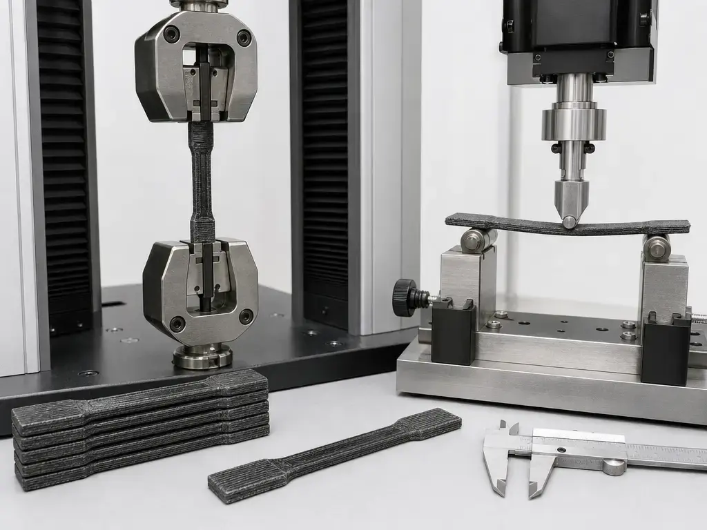
Vendor numbers are useful only when their test context travels with them. [8] Markforged says its fiber data come from fully filled unidirectional 0° plaques printed without walls, and its sheet explicitly warns that customer parts should be tested to customer specifications because performance varies with fiber layout, part design, load case, and build conditions. [8] Anisoprint likewise reports values along printing paths, which means fiber direction is part of the measurement. [11] Published literature shows why this matters. [16] In the basalt study, measured void ranges were 3.5 to 5.6%, 2.9 to 6.7%, and 1.4 to 5.7% depending on material and orientation, while a 2024 defect review cites void content up to 12% in printed CF/PA6 composites and links poor interfaces to reduced properties. [16] [17] A recent review also summarized thermoset continuous-fiber tests using 0.8, 1.0, and 1.2 mm nozzles with 0.75 to 1.1 mm spacing, reporting tensile strengths of 148 to 232 MPa, Young’s moduli of 21.1 to 31.2 GPa, flexural strengths of 220.2 to 345.7 MPa, and flexural moduli of 10.2 to 16.5 GPa. [19] Layer height, dimensional accuracy, and build volume sit in a different category. [9] [10] The X7 is listed at 50 to 250 μm layer height, and the FX20 at up to 525 × 400 × 400 mm build volume depending on nozzle mode, but those machine specifications do not by themselves prove better fit, strength, or repeatability in a finished composite part. [9] [10]
Applications: Where Continuous Fiber 3D Printing Makes Sense
Continuous fiber 3D printing can be suitable for parts that need higher stiffness or load carrying in selected directions, especially when a plain thermoplastic part would be too flexible and a machined metal part would be disproportionate in cost or weight. [19] [21] Manufacturer coupon data help explain the interest. [8] Compared with Onyx alone, Markforged’s reinforced plaque data are much higher in tensile and flexural metrics, while Anisoprint’s PETG-based data show similar direction-specific gains in another system family. [8] [11] Reviews frame these as targeted applications, not universal substitutions. [19] [21]
In practice, the best fits are usually parts with known load paths, limited safety consequences, and a clear reason to use local fiber reinforcement rather than uniform bulk material. [19] [21] That is why the process is often evaluated for engineering aids, tooling, and reinforced polymer components where the fiber can be routed around holes, along arms, or through bending zones. [21] Vendor design guidance uses similar examples, but the broader point is generic: the value comes from directed reinforcement and reduced tooling dependence, not from a claim that every printed composite is structural. [23]
- jigs
- fixtures
- tooling
- brackets
- robotic end effectors
- inspection fixtures
- functional prototypes
- low-volume replacement parts
Limitations and Design Risks
Continuous fiber reinforcement is not a shortcut around mechanical design. [16] [19] These parts are intentionally anisotropic, so the same geometry can behave very differently in the fiber direction, transverse to it, and through its thickness. [16] [18]
The most important risks are composite-specific. [17] Z-direction performance and layer adhesion often trail in-plane performance. [16] [17] Voids, incomplete impregnation, poor fiber-matrix interface quality, fiber breaks, delamination, and shear-dominated failure can all erase the benefit of nominal fiber reinforcement. [17] [19] The 2024 basalt study measured clear directional weakness alongside void ranges from 1.4 to 5.7%, 2.9 to 6.7%, and 3.5 to 5.6%, and the defect-review literature reports void content up to 12% in printed CF/PA6 composites. [16] [17] Fiber orientation can dominate outcomes, and one optimization study found fiber angle contributed 54.13% to the grey relational grade. [18] Moisture sensitivity in nylon-type matrices and limits on how tightly a continuous strand can turn add further design constraints. [17] [19]
There are also practical system-level limits. [19] Continuous-fiber workflows are often slower and more qualification-heavy than plain thermoplastic printing because reinforcement placement, inspection, and repeatability all have to be managed deliberately. [19] Proprietary ecosystems can narrow feedstock choice and toolpath freedom, and costs rise quickly if the part does not benefit from directed reinforcement. [19] Reviews of nozzle size, spacing, and process control in both thermoplastic and thermoset variants show that the process window remains highly parameter-sensitive, so application-specific testing is still safer than assuming coupon values will transfer directly to every part. [19] [21]
Current Research and Market Context
Current research in continuous fiber additive manufacturing focuses on path planning, topology optimization, multi-axis deposition, better impregnation, defect detection, and measurement methods that connect process signals to part quality. [7] [17] [19] NIST treats additive manufacturing of composites as an active metrology area, and recent reviews emphasize the same need for better process-property understanding rather than more headline numbers. [7] [19] Defect detection remains especially important because voids, bonding defects, and fiber-placement errors can be small in scale but large in mechanical consequence. [17]
The market side has been volatile enough that historical context matters. [13] Desktop Metal’s 2019 Fiber launch claimed a 310 × 240 × 270 mm build volume, up to 60% continuous fiber loading, and subscription pricing starting at $3,495 per year for Fiber LT and $5,495 per year for Fiber HT. [13] [14] Those are historical launch claims, not current availability guidance. [13] Arevo should likewise be treated as a historical example unless re-verified on publication day, because Stratasys announced acquisition of Arevo’s technology portfolio on March 4, 2024. [24] The more durable takeaway is that machine ownership changes faster than the underlying engineering questions about reinforcement placement, consolidation, and metrology. [19] [24]
Continuous Fiber 3D Printing: Conclusion for Engineers and Designers
Continuous fiber 3d printing is most useful when the designer can align reinforcement with real load paths and when the application can tolerate anisotropy, testing, and qualification work. [1] [19] In ISO/ASTM terms it belongs within additive manufacturing, but in engineering terms it behaves more like a direction-dependent composite design method than a simple stronger-plastic setting. [1] [19] Published studies show large orientation effects, and optimization work shows that fiber angle can dominate results, so the process rewards path planning more than fiber presence alone. [16] [18] The practical question is not whether continuous fiber is impressive in principle, but whether a specific part can use it honestly and repeatably. [19]
FAQ
What is continuous fiber 3D printing?
It is an additive manufacturing method that places long, uninterrupted reinforcement inside a polymer matrix during printing. [1] The key difference from chopped-fiber filament is that the reinforcement can follow controlled paths and carry load along its length. [8] The main caveat is anisotropy: the printed part is usually much stronger and stiffer along the fiber direction than across it. [16] That makes it a composite-design process, not just a stronger-filament option. [19]
How does continuous fiber reinforcement 3D printing work?
In most systems, the matrix builds the part shape while a separate mechanism adds continuous fiber to selected regions or layers. [8] Dual-nozzle thermoplastic systems place fiber inside the part, co-extrusion systems combine matrix and reinforcement differently, and CF3D-style systems deposit fiber with real-time UV curing. [8] [11] [15] The engineering question is not just whether the machine can place fiber, but whether the fiber can be aligned with the load path and bonded well enough for the intended part. [18] [19]
What materials are used in continuous carbon fiber 3D printing?
Documented examples in this source pool include carbon fiber, fiberglass, aramid/Kevlar-type fiber, and basalt, paired with platform-specific polymer matrices. [8] [11] Markforged documents an Onyx base material and several continuous reinforcements, while Anisoprint documents PETG-based continuous carbon and basalt options with along-path property reporting. [8] [11] Not every machine supports every fiber or every matrix, so compatibility has to be checked per platform rather than assumed from the general term continuous carbon fiber 3D printing. [11] [19]
How do ASTM D3039, D790, D638, and D6641 differ for printed composites?
ASTM D3039/D3039M is the primary in-plane tensile coupon standard for polymer matrix composites reinforced with high-modulus fibers. [3] ASTM D6641/D6641M-23 is for compressive properties using a combined loading compression fixture. [6] ASTM D638 is the tensile standard for plastics, which is useful for base resins but not the primary tensile standard for continuous-fiber composite coupons. [5] ASTM D790-25 covers flexural properties, but it includes a 5.0% strain-limit caveat for cases where the outer surface does not break or yield within that limit. [4] If numbers are compared, the article should also say whether the coupon was unidirectional and whether the value was measured along the fiber path. [3] [11]
Why do fiber angle and load paths matter so much?
Continuous fibers carry load best along their length, so the benefit is highest when the fiber path matches the part’s actual loading path. [16] [19] If the load turns transverse to the fiber or through the thickness, properties can drop sharply and failure can shift toward interface, delamination, or shear problems. [16] [17] One optimization study found fiber angle contributed 54.13% to the grey relational grade, which is a strong reminder that orientation can matter more than some other print settings. [18]
Is Markforged continuous fiber 3D printing worth it?
It can be worth evaluating when a team needs a mature composite material-extrusion workflow and the part benefits from directed reinforcement rather than uniform bulk strength. [8] [23] Markforged is one important vendor example, but its published values are manufacturer coupon data for specific test plaques, not universal finished-part guarantees. [8] The practical test is whether the platform matches your load cases, test methods, matrix needs, and routing constraints better than simpler thermoplastic printing or more conventional composite manufacturing. [19]
Can continuous fiber 3D printed parts replace metal?
Sometimes, in selected applications where the loads, environment, and failure consequences are understood. [19] [21] That does not make metal replacement a general rule. [19] Printed composite parts can still suffer from anisotropy, voids, interface problems, and geometry-dependent weakness. [16] [17] A safer framing is that they can replace some polymer, aluminum, or tooling parts after application-specific testing, not that they automatically match metal or conventionally laminated aerospace composites. [19] [21]
Sources
- ISO/ASTM 52900:2021. Additive manufacturing – General principles – Fundamentals and vocabulary. https://www.iso.org/standard/74514.html
- ISO/ASTM 52903-1:2020. Material extrusion-based additive manufacturing of plastic materials – Feedstock materials. https://www.iso.org/obp/ui?_escaped_fragment_=iso%3Astd%3Aiso-astm%3A52903%3A-1%3Aed-1%3Av1%3Aen
- ASTM D3039/D3039M. Standard Test Method for Tensile Properties of Polymer Matrix Composite Materials. https://store.astm.org/d3039_d3039m-00r06.html
- ASTM D790. Standard Test Methods for Flexural Properties of Unreinforced and Reinforced Plastics and Electrical Insulating Materials. https://store.astm.org/standards/d790
- ASTM D638. Standard Test Method for Tensile Properties of Plastics. https://store.astm.org/standards/d638
- ASTM D6641/D6641M-23. Standard Test Method for Compressive Properties of Polymer Matrix Composite Materials Using a Combined Loading Compression Test Fixture. https://store.astm.org/d6641_d6641m-23.html
- NIST. Additive Manufacturing of Composites. https://www.nist.gov/additive-manufacturing/research-areas/materials/composites
- Markforged. Composites Material Datasheet, Rev. 5.0. https://static.markforged.com/downloads/composites-data-sheet.pdf
- Markforged. X7 Product Specifications PDF. https://www-objects.markforged.com/craft/3d_printers_detail/x7/F-PR-3012.pdf
- Markforged. FX20 Product Specifications PDF. https://web-objects.markforged.com/craft/downloads/F-PR-3016-1.pdf
- Anisoprint. CFC PETG Technical Data Sheet, Ver. 2.1. https://anisoprint.com/wp-content/uploads/2022/03/CFC_PETG_datasheet_March_2022.pdf
- Anisoprint. CFC PETG product page. https://anisoprint.com/cfc-petg/
- Desktop Metal. Fiber continuous fiber 3D printing press release. https://www.desktopmetal.com/press/press-release-desktop-metal-set-to-transform-continuous-fiber-3d-printing
- Desktop Metal. Fiber Material Datasheet PDF. https://www.desktopmetal.com/uploads/DM-0034-00-Fiber_MDS_v191031-1.pdf
- Continuous Composites. Technology / CF3D. https://continuouscomposites.com/technology/
- Polymers. 3D Printing of Continuous Basalt Fiber-Reinforced Composites: Characterization of the In-Plane Mechanical Properties and Anisotropy Evaluation. https://www.mdpi.com/2073-4360/16/23/3377
- Polymers / PMC. Detecting Multi-Scale Defects in Material Extrusion Additive Manufacturing of Fiber-Reinforced Thermoplastic Composites. https://pmc.ncbi.nlm.nih.gov/articles/PMC11548215/
- Results in Engineering. Optimization of infill density, fiber angle, carbon fiber layer position in 3D printed continuous carbon-fiber reinforced nylon composite. https://www.sciencedirect.com/science/article/pii/S2590123024001798
- Polymers. 3D Printing Continuous Fiber Reinforced Polymers: A Review of Material Selection, Process, and Mechanics-Function Integration for Targeted Applications. https://www.mdpi.com/2073-4360/17/12/1601
- Composites Part A. Material extrusion additive manufacturing of continuous fibre reinforced polymer matrix composites: A review and outlook. https://www.sciencedirect.com/science/article/pii/S1359836821005266
- Additive Manufacturing. Additive manufacturing of continuous fiber reinforced polymer composites: Design opportunities and novel applications. https://www.sciencedirect.com/science/article/abs/pii/S2452213921002837
- Formlabs. Carbon Fiber 3D Printing Guide: Printers and Materials Comparison. https://formlabs.com/eu/blog/carbon-fiber-3d-printing-guide-printers-materials-comparison/
- Markforged. Composites Design Guide. https://static.markforged.com/downloads/CompositesDesignGuide.pdf
- Stratasys. Acquisition of Arevo Technology Portfolio. https://investors.stratasys.com/news-events/press-releases/detail/880/stratasys-acquires-arevos-technology-portfolio