
Summary
CLIP 3d printing is a continuous vat-photopolymerization approach that uses an oxygen-controlled interface so a resin part can grow without the usual stop-start peel cycle. The original CLIP paper introduced that mechanism, and a 2024 review places CLIP within continuous DLP inside the broader vat-photopolymerization family. [4] [3]
This article keeps CLIP within the ISO/ASTM vat-photopolymerization family rather than treating it as a separate standards category, and it separates the CLIP mechanism from Carbon DLS as a commercial platform. It also treats washing, post-cure, and validation as part of the process, not as afterthoughts, because Carbon’s dual-cure framing distinguishes the green printed shape from the final cured material state. Before quoting performance figures, it defines resolution, accuracy, repeatability, and throughput so machine optics are not confused with finished-part results. [1] [2] [8] [9] [10]
CLIP in one minute: taxonomy + the “Is it SLA?” answer
CLIP belongs within vat photopolymerization, the ISO/ASTM process family for additive manufacturing methods that cure photopolymer resin in a vat. It is best described as a proprietary, continuous, oxygen-controlled implementation within that family, not as a separate standards-level AM category. A 2024 review describes CLIP as continuous DLP, which distinguishes the method without moving it outside vat photopolymerization. [1] [2] [3]
Is CLIP a type of SLA? Not in the usual practical sense. Both SLA and CLIP sit within vat photopolymerization, but SLA commonly implies laser-scanned exposure, while CLIP uses projected light plus an oxygen-controlled continuous interface that is often described as continuous DLP. It is related to SLA at the family level, but different in mechanism and workflow. [3] [4]
| Process term | How light is patterned | Interface / separation behavior | Caution for readers |
|---|---|---|---|
| SLA | A laser scans the cross-section. | Commonly run as discrete layers, with recoating or separation behavior determined by machine architecture. | In practical usage, SLA usually means laser-written resin printing, not every resin process. [1] [2] |
| DLP | A projected image cures each slice. | Commonly slice-based, so fabrication still includes layer-to-layer transitions. | Projected light alone does not make a process continuous. [2] [3] |
| MSLA/LCD | A masked image cures each slice through an LCD-style mask. | Also generally slice-based, with discrete exposure updates. | Screen or pixel structure is not the same thing as finished-part tolerance. [2] [3] |
| CLIP | A projected image cures resin through an oxygen-permeable window. | An oxygen-inhibited dead zone helps maintain a persistent uncured interface so the part can be drawn continuously. | XY pixel size does not equal dimensional tolerance. [3] [4] |
| Carbon DLS | Carbon packages continuous projected-light photopolymerization into a commercial hardware, software, and materials workflow. | Platform behavior includes printer controls, validated materials, and post-cure steps, not only the window interface. | Do not treat Carbon DLS as a synonym for every continuous resin process. [6] [8] [12] |
The key point is simple: CLIP is a continuous photopolymerization approach, SLA usually means a laser-written resin process, and Carbon DLS is Carbon’s commercial platform around continuous behavior plus validated materials and downstream controls. That distinction matters when comparing claims about speed, accuracy, or “layerless” printing across resin systems. [1] [3] [4] [8]
What is Continuous Liquid Interface Production (CLIP)?
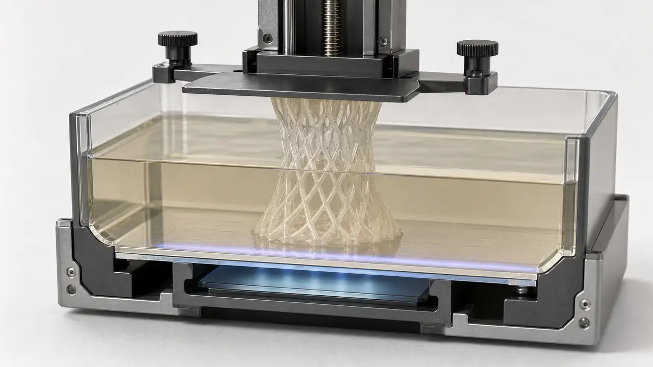
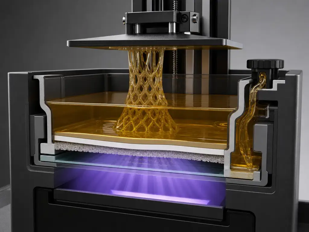
Continuous Liquid Interface Production, or CLIP, is a vat-photopolymerization process in which a resin part is drawn upward while light cures it through a window at the bottom of the vat. Its defining feature is an oxygen-inhibited dead zone: a thin uncured liquid interface between the curing part and the window where photopolymerization is suppressed. In the original research, that dead zone was on the order of tens of micrometers, and the follow-on PNAS paper described the process as oxygen-inhibited photopolymerization that creates a continual liquid interface of uncured resin between the growing part and the exposure window. [4] [5]
Here, “continuous” means the build can proceed without the repeated stop-and-separate cycle used in many bottom-up layer-based systems. It does not mean there is no slicing, no optical control, or no process planning. CLIP still depends on projected images, resin behavior, and tightly controlled operating conditions, even when visible layer artifacts are reduced. [4] [5]
How CLIP works (mechanism, step-by-step)
In the original CLIP paper, ultraviolet images were projected through a transparent window at the bottom of the resin vat while the part was drawn upward. That window was an amorphous fluoropolymer, Teflon AF 2400, chosen for high oxygen permeability as well as UV transparency and chemical inertness. Oxygen diffusing through the window creates the oxygen-rich interface where cure is inhibited, so the part does not bond directly to the window during growth. [4]
That interface control is the central engineering feature. In many bottom-up vat systems, each layer must separate from the window and fresh resin must reflow before the next exposure. CLIP reduces much of that stop-start burden by maintaining a controlled dead zone and continuous resin renewal beneath the rising part. The original paper reports oxygen permeability of 1000 barrers for the Teflon AF 2400 window, dead-zone thickness on the order of tens of micrometers, and continuous draw rates of hundreds of millimeters per hour. It also ties dead-zone thickness to control parameters such as photon flux and resin optical and curing properties, which means the process window is set by physics and chemistry rather than motion alone. The follow-up PNAS work supports careful language about reduced staircasing and reported isotropic mechanical properties under the studied conditions, not blanket promises for every resin or geometry. [4] [5]
Those dead-zone, permeability, and draw-rate figures are historical research values from the 2015 Science paper, not published specifications for current Carbon cassettes or universal guarantees for present-day production jobs. [4]
CLIP vs Carbon DLS: what’s the same, what’s not
CLIP is the underlying Continuous Liquid Interface Production mechanism; Carbon DLS is Carbon’s commercial platform built around that approach. Carbon publicly introduced CLIP on March 16, 2015, and independent coverage from the same day corroborates that timeline. When people say “Carbon DLS,” they are usually referring not just to the oxygen-controlled print mechanism but to the broader production stack of hardware, software, materials, and process control. [6] [7] [8]
That platform-level distinction matters because final part behavior depends on more than the oxygen window. Carbon’s dual-cure framing says UV exposure sets the printed shape first, then a later baking step activates thermally curable components and develops the final polymer network. Carbon’s design guidance also treats dimensional results as geometry- and material-dependent, which is a reminder that validated settings, post-cure, and inspection plans matter alongside the printer itself. [8] [12]
CLIP 3D printing process workflow (design → print → wash → cure)
In practical use, CLIP 3D printing is a workflow rather than a single machine event. The printed part first emerges in a green state, meaning the geometry has been formed but the material response may not yet match its final condition. Carbon’s dual-cure materials white paper describes this as UV chemistry defining the shape during printing, followed by a later baking step that develops the final network and final properties. That is why design intent, resin selection, cleaning, and cure sequencing belong in the process definition from the start. [8]
For production use, inspection and validation belong inside the main process. Carbon’s design guide explicitly states a first-print accuracy assumption and ties dimensional outcome to geometry, resin, and baking method, so acceptance criteria should be based on the real part and workflow rather than on a single nominal printer number. [12]
- CAD/design + orientation. Define the part, orientation, drainage, and support strategy around the geometry you need to manufacture. [12]
- Material/workflow selection. Choose a validated resin and the matching wash and cure schedule for the target property set. [8] [12]
- UV projection + continuous build. Projected light cures the resin while the part is drawn upward through the oxygen-controlled interface, leaving the geometry in a green state. [4] [8]
- Part removal. Remove the printed part from the platform using the handling method defined for the workflow. [8]
- Washing/cleaning. Remove residual uncured resin using the resin-specific cleaning protocol rather than a generic “resin printer” assumption. [8] [23]
- Support removal. Remove supports in the stage and sequence intended by the workflow and geometry. [12]
- UV and/or thermal post-cure. Complete the manufacturer-defined cure sequence that develops final properties and stabilizes the part. [8] [23]
- Inspection/validation & documentation. Check dimensions or function against the intended specification and document build conditions where production repeatability matters. [12] [21]
Metrics framework (mandatory definitions before any performance numbers)
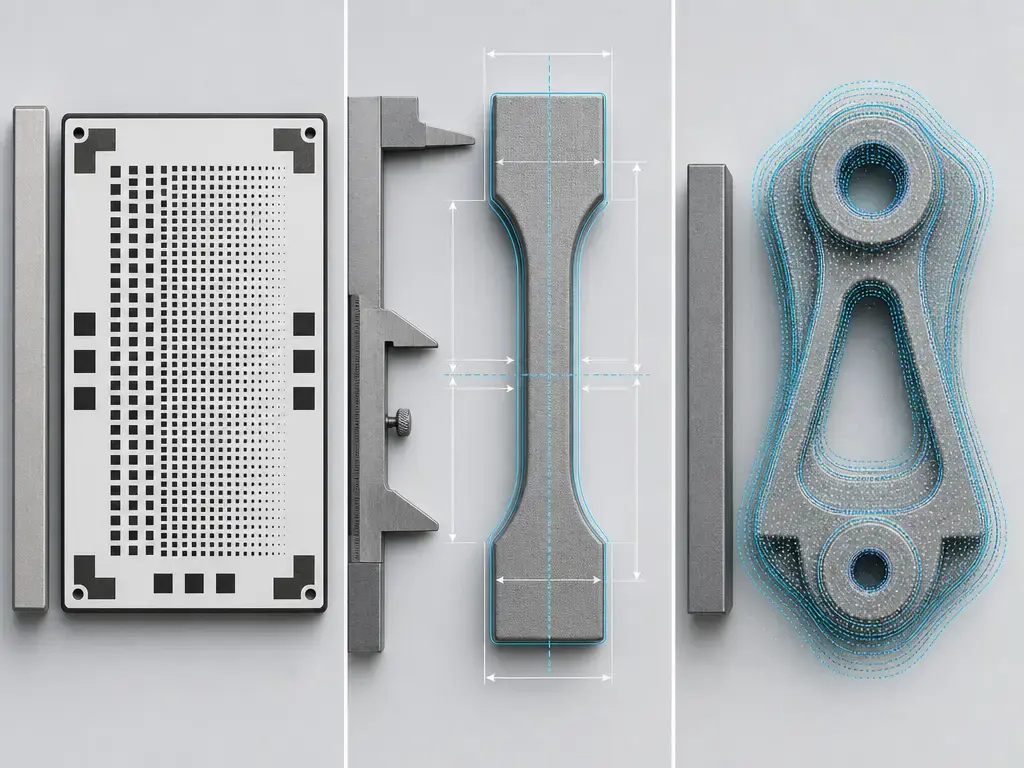
AM articles often mix up optical system limits with finished-part results. In CLIP discussions, that usually means pixel size, slice thickness, minimum feature size, dimensional accuracy, and repeatability get treated as if they were interchangeable. Metrology guidance does not support that shortcut: NIST warns that terms such as accuracy and precision are often misused when they are not tied to a defined measurement context, and the VIM keeps accuracy, trueness, precision, repeatability, and reproducibility distinct. [9] [10]
The practical split is this: some metrics belong mainly to the machine or optics, while others belong to the measured part in a defined workflow. Carbon’s dental documentation makes that difference visible by reporting certain outcomes as the percentage of scan points inside a tolerance band, while machine pages separately publish XY and Z resolution values. A point-cloud agreement claim, a pixel-size claim, and a dimensional tolerance claim can all be useful, but they answer different questions. [11] [12] [18] [20]
| Term | What it is | Typical unit/reporting | What it is NOT |
|---|---|---|---|
| XY resolution | The smallest lateral optical pixel or projected increment the system addresses in the build plane. | Usually reported in µm. | Not a direct promise of dimensional tolerance on a finished part. [10] [11] [12] |
| Z increment | The nominal slice thickness or commanded vertical increment used in job setup. | Usually reported in µm per slice setting. | Not the same thing as universal physical layer thickness in every continuous process. [11] [12] |
| Minimum feature size | The smallest geometry the process can reliably reproduce in context. | Often reported by design guide, test geometry, or application study. | Not a single universal printer-spec number. [12] |
| Dimensional accuracy | Closeness of a produced dimension to its intended or reference value in a defined measurement setup. | Often reported as ± offset plus a scale term, or as deviation from nominal. | Not the same as pixel size, Z increment, or repeatability. [9] [10] [11] [12] |
| Repeatability | Closeness of agreement between results under the same conditions. | Reported through a process window, a variation band, or repeat measurements. | Not the same as trueness or a one-time accuracy result. [9] [10] |
| Throughput | Parts or models produced per unit time in a defined workflow. | Parts/day, models/shift, jobs/day, or similar. | Not the same as raw draw rate in mm/hour. [4] [19] [20] |
| Dental point-cloud accuracy | Percentage of measured surface points that fall inside a stated tolerance band against a reference model. | Reported as % of points within ±X µm. | Not a generic printer-resolution spec. [18] [20] |
Performance: speed, resolution, accuracy, repeatability, isotropy (context-driven)
For CLIP, speed needs two separate frames. The original 2015 paper reported monolithic polymeric parts up to tens of centimeters in size, feature resolution below 100 µm, and draw rates of hundreds of millimeters per hour. It also gave a specific example in which gyroid and argyle structures were printed at 500 mm/hour and reached about 5 cm in less than 10 minutes. Those are research-era process-rate figures, not blanket factory-throughput claims. Carbon’s production-oriented numbers are reported differently: the orthodontics page says a single L1 printer can produce 800–1000 clear aligner models per day, while the L1 thermoforming one-pager says up to 1900 models per day and 30 models in as few as 20 minutes for a specific workflow. Because those manufacturer figures differ, they should be read as workflow-specific throughput claims rather than universal machine speed. [4] [19] [20]
Resolution and accuracy are separate topics. Carbon’s M3/M3 Max page lists an M3 build volume of 189 × 118 × 326 mm, an M3 Max build volume of 307 × 163 × 305 mm, XY resolution of 75 µm, Z resolution of 25, 50, or 100 µm, and a general accuracy figure of up to ±65 µm + 1 µm per mm. Carbon’s design guide separately gives a first-print assumption of ±70 µm + 1 µm per mm and explicitly says accuracy depends on geometry, resin, and baking method. So a published 75 µm XY value is an optics or addressability figure, not a promise of ±75 µm dimensional outcome on every part. [11] [12] [9]
Isotropy needs the same caution. The PNAS paper reported reduced staircasing and isotropic mechanical properties under the cited conditions, which helps explain why CLIP is often associated with smoother surfaces and less direction-dependent behavior than many stepped builds. But those outcomes remain conditional on resin chemistry, geometry, and cure schedule, so “reported under the studied conditions” is the accurate phrasing. [5] [3]
Materials & resins used in CLIP resin 3D printing (validated families only)
CLIP resin 3D printing is best understood as a process-material system, not as a printer that accepts any generic hobby photopolymer. The original CLIP literature is about curing liquid photopolymer resin through a controlled oxygen-inhibited interface, while Carbon’s commercial framing adds validated material families, wash steps, and post-cure sequences on top of that mechanism. The material definition therefore includes how the part is printed and finished, not just which liquid starts in the vat. [4] [8]
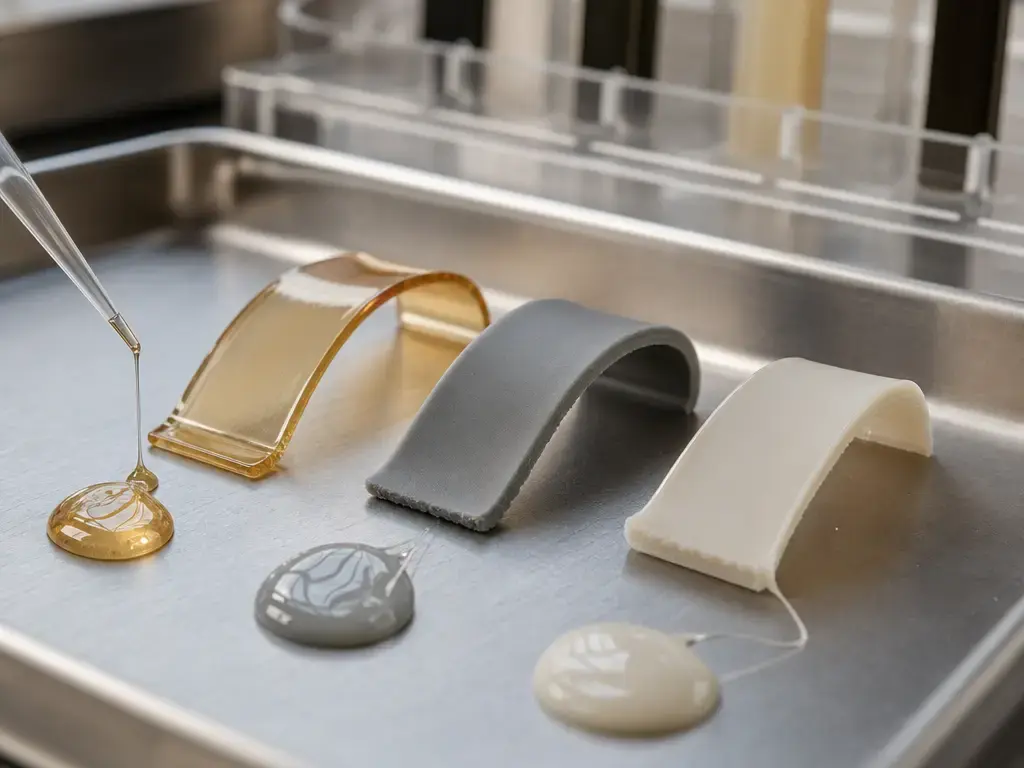
That becomes clearer in dual-cure systems. Carbon describes dual-cure materials as resin formulations in which UV-curable chemistry sets the shape during printing, followed by a secondary baking step that activates thermally curable components and forms a separate polymer network in the final part. The green part is only the first stage of the material story. A part that looks correct immediately after printing may still change in mechanical response, dimensional behavior, and service suitability after cleaning and final cure. That is one reason hobby SLA-style shorthand does not transfer cleanly to production-oriented CLIP/DLS materials. [8]
When reading a technical data sheet, keep the test context attached to the number. For photopolymer systems, revision date, test standard, specimen type, test rate, wash method, conditioning, and cure state all matter. The same material family can show different values under different specimen forms or processing routes, and current public documentation can also change over time, as shown by the DPR 10 TDS at the cited URL now being Rev E dated 2026-05-20. [13] [14] [15] [16] [17]
Property citation rule: Any property number in a CLIP/DLS materials discussion should stay attached to the TDS revision/date, test standard, specimen type, test rate, and processing or conditioning state in the same or adjacent sentence. If that context is missing, omit the number. [13] [14] [15] [16] [17]
- Rigid polyurethanes — RPU 70. Carbon’s RPU 70 TDS, Rev F dated 2026-06-23, reports 1700 MPa tensile modulus, 40 MPa ultimate tensile strength, and 30% elongation at break for ASTM D638 Type I specimens tested at 50 mm/min. The same TDS reports 100% elongation at break for ASTM D638 Type V at 10 mm/min. The test parts were processed on an M series printer, washed in a Smart Part Washer with VF 1, and baked on the standard RPU 70 schedule. [13]
- Elastomeric polyurethanes — EPU 45. Carbon’s EPU 45 TDS, Rev E dated 2026-05-28, reports 18 MPa tensile modulus, 24 MPa ultimate tensile strength, and 240% elongation at break for ASTM D412 Die C at 500 mm/min in the IPA-washed condition on page 5. A separate general-properties row reports Shore A hardness of 77 instant / 62 at 5 sec after L-series printing and standard bake. That split is a good example of why wash protocol and test context must stay attached to the number. [15]
- Epoxies — EPX 82. Carbon’s EPX 82 TDS, Rev H dated 2026-05-28, reports 2800 MPa tensile modulus, 80 MPa ultimate tensile strength, and 5% elongation at break for ISO 527-2 Type IA at 5 mm/min, plus heat deflection temperature of 130 °C at 0.455 MPa per ASTM D648. The same TDS says samples were kept dry and tested within 24 hours after baking, and that parts were printed on an M series printer, washed with DPM followed by an isopropanol dunk, then baked on the standard EPX 82 schedule in an air oven. [14]
- Silicone urethanes — SIL 30. Carbon’s SIL 30 TDS, Rev G dated 2026-05-28, describes SIL 30 as a silicone urethane elastomer and reports 350% elongation at break for ASTM D412 Die C at 500 mm/min plus Shore A hardness of 35 instant / 31 at 5 sec. The test parts were printed on an M series printer, washed with VF 1, and baked on the standard SIL 30 schedule. [16]
- Cyanate esters — chemistry example only. A peer-reviewed study describes CE 221 Part A as 4,4′-ethylidenediphenyl dicyanate, meaning a bisphenol E cyanate ester. That is useful chemistry-family evidence, but it is not proof of current public product availability or present-day validation status. [26]
- Dental/model resins — DPR 10. The current DPR 10 TDS at the cited URL is Rev E dated 2026-05-20 and describes DPR 10 as suitable for manufacturing dental models and other applications where high accuracy is needed. [17]
Applications: where CLIP / DLS is used (attributed, non-hype)
Dental models and thermoforming workflows are the clearest publicly documented use cases. Carbon’s DPR 10 material documentation describes it as suitable for dental models where high accuracy is needed, and Carbon’s April 2021 update reports outcomes as percentages of scan points within tolerance bands, including 94% of points within ±50 µm (±5%) for DPR 10 model-plus-die local accuracy and 96% of points within ±100 µm (±5%) for clear aligner models. Carbon’s orthodontics page says a single L1 can produce 800–1000 clear aligner models per day, while its thermoforming one-pager says up to 1900 models per day and 30 models in as few as 20 minutes for a specific workflow. Those figures should be read as manufacturer-attributed, workflow-specific outputs rather than universal CLIP throughput. [17] [18] [19] [20]
Beyond dentistry, peer-reviewed work has used Carbon EPU 41 on a Carbon L1 to print lattice pucks for cushioning studies, which provides an independent example of the process in compliant lattice structures. An independent dental study describing interim crown fabrication also defines DLS/CLIP in mechanistic terms as oxygen-inhibited photopolymerization that creates a continuous liquid interface between the growing part and exposure window. For broader industrial categories, Carbon’s design guide lists common uses such as housings, electrical connectors, cushioning, vibration isolation, and fixtures for baking. Taken together, the strongest public use-case picture is dental models, lattice cushioning, and validated functional polymer parts where geometry, material response, and post-cure must all be controlled together. [24] [25] [12]
Design rules & process limitations (grounded, not ad-libbed)
CLIP should be treated as geometry-dependent manufacturing, not as a fixed-tolerance box. Carbon’s design guide says to assume ±70 µm + 1 µm per mm for a first print and explicitly lists part geometry, resin, and baking method as accuracy drivers. That means a tuned production result can differ from a first-print expectation, and it is why “printer accuracy” should not be reduced to one standalone number without geometry context. [12]
The underlying physics set real limits. The original CLIP paper ties continuous operation to dead-zone control, resin renewal, viscosity, photon flux, and resin optical and curing behavior. The 2024 review similarly places CLIP within a broader continuous DLP research space motivated by the layer delamination, recoating, and transition-time limits of conventional slice-based systems. None of that means CLIP eliminates process forces or thermal effects; it means those constraints are managed differently. Resin still has to flow into the curing zone, the oxygen-inhibited interface has to remain stable, and heat generation and post-cure can still influence deformation or final properties. The PNAS paper supports careful language about reduced staircasing and reported isotropic properties, but not a universal claim that the usual physical constraints disappear. [4] [5] [3]
A second limitation is ecosystem control. In public documentation, CLIP is most often encountered through Carbon’s DLS platform, validated workflows, and material documentation rather than as an open recipe for arbitrary resins and post-processing. That can help repeatability, but it also means users should expect validation overhead rather than simple resin-swapping behavior. [8] [12]
- Proprietary ecosystem. Public CLIP discussion is usually tied to Carbon’s platform, documentation, and validated material workflows rather than to an open drop-in recipe. [8]
- Resin/workflow validation. Final properties depend on the full sequence, including print state, cleaning, and post-cure. [8]
- Geometry-dependent accuracy. Narrow features, large spans, and orientation changes do not obey one universal tolerance number. [12]
- Post-processing sensitivity. Wash method and final cure can change both dimensions and material response. [8] [12]
- Resin viscosity limits. Continuous resin renewal and dead-zone stability depend on fluid behavior and cure kinetics. [4]
- Heat/exotherm/thermal management. Printing and post-cure both introduce thermal constraints that affect process control and final outcome. [4] [8]
- Safety handling & waste. Uncured resin, cleaning media, and contaminated consumables require SDS-based handling and disposal practices. [21] [23]
- Application-specific inspection. Validation should be based on the real part, measurement method, and acceptance criteria, not a generic printer spec. [12]
Safety & compliance essentials (keep short, SDS-first)
For CLIP resin handling, start with the Safety Data Sheet and your site’s hazard communication procedures. OSHA’s Hazard Communication Standard requires employers to provide hazard communication through labels and other forms of warning, safety data sheets, and information and training. PAMA’s practical guidance reinforces the same baseline by telling users to consult supplier SDSs as the primary safety and handling documents and to use appropriate PPE. For this article, that is the right level of guidance: SDS first, then facility procedures, then job-specific controls. [21] [23]
Ventilation and emissions should be handled cautiously rather than assumed from the printer category. The U.S. Consumer Product Safety Commission references UL 2904 as a standard method for testing and assessing particle and chemical emissions from 3D printers. That is useful because it confirms that emissions testing methods exist, not because it proves every resin platform has the same exposure profile. Follow the SDS, manufacturer guidance, and any site ventilation rules for the actual resin, wash chemistry, and operating setup you use. [22] [23]
Current research & related continuous vat methods (clearly labeled research)
Current research treats CLIP as part of a broader continuous vat-photopolymerization landscape rather than as a single frozen recipe from 2015. The 2024 review places CLIP in the continuous DLP branch of vat photopolymerization and uses it as a mechanism example built around an oxygen-permeable window and dead zone. That framing is useful for taxonomy and mechanism, but it is not the same thing as a current commercial specification sheet. The core variables remain the ones identified in the original paper: photon flux, resin optical behavior, resin curing behavior, and oxygen-controlled interface conditions. [3] [4]
The research direction is mainly about tighter control of process windows, not elimination of process dependence. The PNAS follow-up reported reduced staircasing and isotropic mechanical properties under its studied conditions, while the 2024 review emphasizes that continuous DLP emerged partly to reduce delamination, recoating, and transition-time penalties in slice-based resin systems. Research literature therefore supports careful claims about improved continuity, interface control, and smoother outcomes under defined conditions, but those findings should not be read as automatic proof of current commercial hardware capability for every resin or part geometry. [5] [3] [4]
What CLIP 3D printing is best for — and when another process wins
In practice, CLIP 3d printing is best matched to applications where a validated resin system, controlled post-cure, smooth surfaces, and production traceability matter together. That includes well-documented cases such as dental model production and selected functional polymer parts, and it also fits complex elastomeric lattices where geometry repeatability and downstream cure are part of the value proposition. The key selection logic is workflow-based: published machine optics, the material TDS, and the cure sequence all contribute to final performance, and Carbon’s own documentation treats dimensional outcome as geometry- and material-dependent rather than universal. [8] [11] [12]
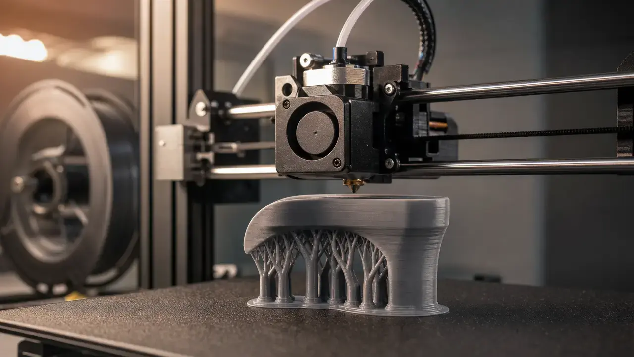
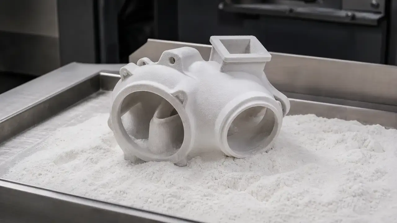
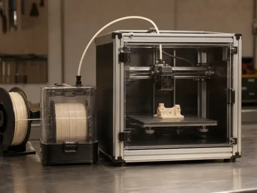
Another process can be the better choice when the requirement is low-cost thermoplastic prototyping, broad commodity material choice, very large nylon-oriented production, or a simpler workflow with less post-cure dependence. In those cases, FFF/FDM, powder-bed polymer processes, or another vat-photopolymerization platform may fit better. The useful comparison is not which printer is “fastest,” but which process family best matches the geometry, material behavior, inspection burden, and production context of the part.
FAQ
What is CLIP 3d printing (continuous liquid interface production)?
Continuous Liquid Interface Production is a vat-photopolymerization process that cures resin through a bottom window while maintaining a thin oxygen-inhibited uncured interface between the window and the growing part. That persistent interface lets the part be drawn upward more continuously than in many stop-start bottom-up systems. Independent review literature describes CLIP as continuous DLP within the broader vat-photopolymerization family, which is the clearest way to place it without inventing a new AM category. [3] [4]
How does continuous liquid interface production work, step by step?
A projected UV image cures the resin through the bottom window of the vat while oxygen diffusing through that window suppresses cure in a thin dead zone next to the interface. Because the part does not fully bond to the window, it can be drawn upward while fresh resin renews the gap below. The original paper tied that behavior to photon flux and resin optical and curing properties, so continuous motion still depends on tightly controlled chemistry and optics. [4] [5]
Is Carbon DLS the same as CLIP?
No. CLIP 3D printing is the underlying continuous photopolymerization approach, while Carbon DLS is Carbon’s commercial platform around that approach, including hardware, software, validated materials, and downstream cure workflow. That distinction matters because a Carbon platform claim about throughput, material properties, or dimensional behavior is not just a claim about an oxygen-permeable window. Carbon’s guidance also says dimensional outcome depends on geometry, resin, and baking method. [6] [8] [12]
Is CLIP actually “layerless,” or just more continuous than SLA/DLP?
“Layerless” is best treated as attributed shorthand rather than as a literal technical definition. Carbon’s 2015 press release used that wording, and the PNAS follow-up discussed reduced staircasing and reported isotropic mechanical properties under the studied conditions. The safer engineering description is that CLIP uses a continuous oxygen-inhibited interface that can reduce visible layer artifacts and eliminate much of the usual stop-and-separate cycle found in many slice-based bottom-up systems. [6] [5] [4]
What resins/material families are used for CLIP / DLS, and why aren’t hobby resins equivalent?
Public Carbon documentation supports rigid polyurethane, elastomeric polyurethane, epoxy, silicone-urethane, and dental/model material families, with cyanate ester chemistry also documented in a peer-reviewed study as a chemistry example. Hobby resins are not equivalent because CLIP/DLS material behavior is documented as a workflow that includes print state, wash method, and final cure. In dual-cure systems, the printed green part is only the first stage of the material. [8] [13] [14] [15] [16] [17] [26]
How fast is CLIP compared with other vat photopolymerization methods (mm/h vs parts/day)?
Use two speed frames, not one. The original CLIP paper reported draw rates of hundreds of millimeters per hour and gave a 500 mm/hour example that reached about 5 cm in under 10 minutes, which is a process-rate metric. Carbon’s production pages instead report workflow throughput, such as 800–1000 clear aligner models per day for a single L1 on one page and up to 1900 models per day plus 30 models in as few as 20 minutes on another. Those manufacturer figures are workflow-specific, not universal. [4] [19] [20]
What controls dead-zone thickness and why does it matter for accuracy and surface finish?
In the original CLIP work, dead-zone thickness was on the order of tens of micrometers and was controlled by parameters including photon flux and resin optical and curing properties. It matters because the dead zone keeps the part from bonding to the window while also influencing how sharply the cure front is controlled near the interface. If the zone becomes unstable, adhesion, resin renewal, and dimensional behavior can all suffer, so the dead zone is a core process-control variable rather than a marketing detail. [4] [3]
Sources
- ISO/ASTM 52900:2021 Additive manufacturing — General principles — Fundamentals and vocabulary
- NIST — Vat photopolymerization
- Nature review — CLIP as continuous DLP within vat photopolymerization
- Tumbleston et al. Science 2015 PDF copy — Continuous liquid interface production of 3D objects
- Janusziewicz et al. PNAS 2016 — Layerless fabrication using CLIP
- Carbon press release — Carbon3D introduces CLIP breakthrough technology for layerless 3D printing
- Washington Post — Independent March 2015 timeline corroboration
- Carbon dual-cure materials white paper
- NIST Technical Note 1297 Appendix D1 — Terminology
- JCGM 200:2012 International Vocabulary of Metrology (VIM)
- Carbon M3 / M3 Max product page
- Carbon DLS Design Quick Guide
- Carbon RPU 70 technical data sheet
- Carbon EPX 82 technical data sheet
- Carbon EPU 45 technical data sheet
- Carbon SIL 30 technical data sheet
- Carbon DPR 10 technical data sheet, Rev E, 2026-05-20
- Carbon — April 2021 platform update: dental accuracy guidelines
- Carbon orthodontics industry page
- Carbon L1 thermoforming one-pager
- OSHA Hazard Communication Standard 29 CFR 1910.1200
- CPSC voluntary standards page referencing UL 2904
- PAMA 3D printer safety poster
- Peer-reviewed lattice/cushioning study using Carbon EPU 41 on Carbon L1
- Dental interim crowns study mentioning DLS/CLIP mechanism
- CE 221 cyanate ester chemistry confirmation (peer-reviewed)