
Summary
Artec Leo is a credible candidate for the best 3d scanner for automotive when the job is close-range, mobile, and centered on reference geometry rather than certified inspection. Artec lists vendor-stated 3D point accuracy up to 0.1 mm and a working distance of 0.35 to 1.2 m, which fit that role well. [S1]
In automotive 3D scanning, Leo fits reverse-engineering reference meshes, restoration and custom-fabrication work, interior capture, underbody access, and vehicle documentation or forensics. It is not a universal best choice for inspection-grade metrology, very small features, or automated hail-damage assessment. Artec’s own scan guidance still flags black, transparent, and reflective surfaces as difficult, and NIST’s structured-light review is a reminder that results depend on surface condition, setup, alignment, and validation context, not only on brochure numbers. [S3] [S17]
A quick decision filter: what “best” means in automotive
For a 3D scanner for automotive work, “best” depends on the deliverable. One job may need a reference mesh for design, packaging, or fitment checks. Another may need a scan-to-CAD starting point for rebuilding engineering surfaces. A third may need deviation maps that support tolerance decisions on sheet-metal assemblies. A fourth may need geometry for documentation or accident reconstruction. Those outcomes place different weight on mobility, registration, and measurement proof. [S25]
The key distinction is capture feasibility, registration quality, and inspection validity. A scanner can capture a part at useful visual detail yet still leave difficult alignment across multiple passes, or geometry that is not defensible for a tolerance claim. ISO 10360-8 is specifically about Cartesian CMMs with optical distance sensors, not handheld scanners as a blanket category. ISO 10360-13 covers acceptance and reverification of optical 3D coordinate measuring systems, and it applies only when the scanned surface stays within a cooperative range. VDI/VDE 2634 Part 2 and Part 3 frame optical area-scanning and multi-view registration in a common coordinate system, which is why alignment strategy matters so much in large vehicle jobs. [S18] [S19] [S21] [S22]
- If you need a reference mesh for reverse engineering, prioritize stable capture, workable exports, and enough surface detail to rebuild from.
- If you need scan-to-CAD, prioritize registration quality and a workflow that supports mesh cleanup before surfacing.
- If you need inspection, prioritize traceable alignment, deviation mapping, and a standards-aware validation process.
- If you need accident reconstruction, prioritize documentation geometry that can be reviewed later within a broader evidentiary workflow.
- If you need full-vehicle coverage, prioritize segmentation, overlap control, and post-processing resources.
- If you need field mobility, prioritize a handheld workflow that can move around the vehicle without a fixed capture cell.
Historical background: from discrete measurement to full-surface capture
Automotive and forensic vehicle measurement did not begin with handheld scanners. SAE notes that collision-reconstruction workflows have long used total stations, CMMs, laser scanning, and traditional photogrammetry to capture vehicle geometry, each with different tradeoffs in speed, coverage, and dimensional control. That background helps explain why current automotive work often asks for full-surface digital reference geometry and deviation fields, not just a sparse set of measured points. [S26]
How Artec Leo works for automotive capture
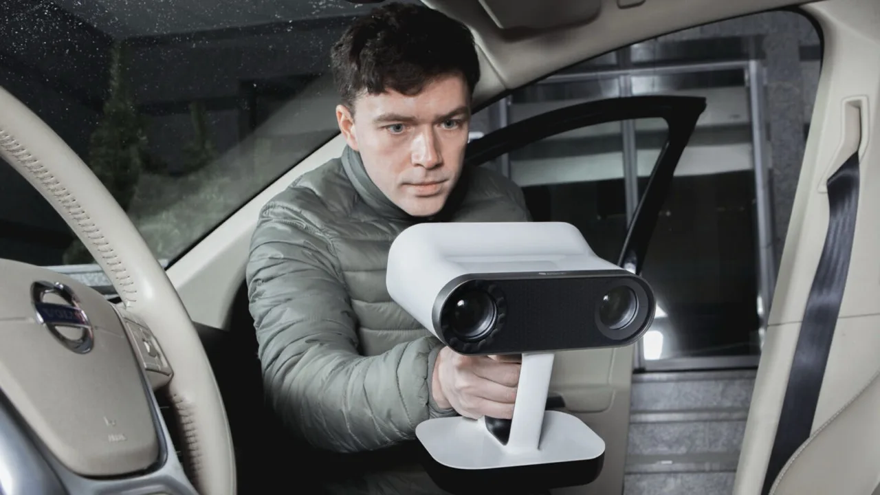
Leo is a handheld structured-light scanner that uses a VCSEL light source at 808 nm and is listed by Artec as Class 1. The scanner performs on-board real-time processing and uses overlapping frames to maintain tracking as you move around an object, so it can be used as a standalone device without a tethered PC during capture. For automotive work, that matters because you can move around a bumper, door skin, dashboard section, or stripped shell without dragging a laptop cart through the shop. Artec lists a working distance of 0.35 to 1.2 m, a volume capture zone of 160,000 cm³, data acquisition up to 3 million points per second in SD and 35 million points per second in HD, plus distinct rates of up to 22 fps for real-time fusion, 44 fps for 3D video recording, and 80 fps for 3D video streaming. Artec’s scan documentation also says the optimal distance for most objects is about 0.5 m, which is a practical starting point for car panels and interior components. [S1] [S3]
In downstream work, Leo data is usually registered and fused into meshes, point clouds, or both, then exported for cleanup, measurement, or CAD-adjacent workflows. Artec Studio currently lists mesh, point-cloud, measurement, and CAD exports, including STEP, IGES, and X_T. That still does not mean Leo outputs editable parametric CAD automatically. The normal chain is scan, registration, mesh cleanup, optional reverse-engineering surfacing, then CAD rebuilding and validation. [S8]
HD Mode is useful, but it is not free accuracy. Artec’s documentation says HD frames are heavy enough that Leo cannot save every frame in HD, so the recommended recording frequency is 1/8. Artec support materials also say HD Mode can increase resolution by up to 2× under the right conditions, but it is resource-intensive and increases project size, import time, and surface-construction time. For post-processing, Artec recommends 32 GB RAM as a minimum and 64+ GB for larger HD projects. In automotive terms, HD can help preserve finer detail on parts and textured surfaces, but it does not by itself validate a measurement result. [S5] [S6] [S7]
How to use Artec Leo for automotive 3D scanning
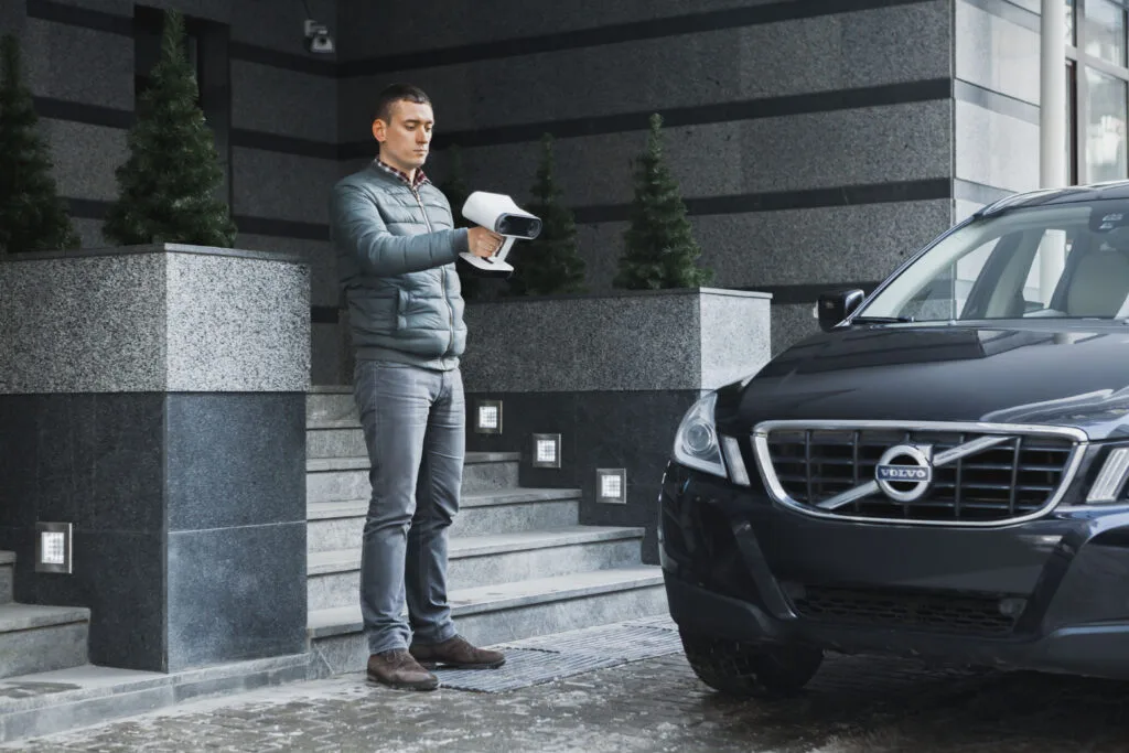
If you are asking how to use artec leo for automotive 3d scanning, start with the deliverable before you start the scan. Decide whether the job needs a documentation mesh, a reverse-engineering reference, or data that will feed a tighter inspection workflow later. Leo’s working-distance window makes it practical for close-range panels, interiors, and assemblies, while Artec Studio’s export options support downstream workflows without implying automatic CAD reconstruction. [S1] [S8]
Surface preparation is where automotive reality starts. Artec’s scan guidance says the object should be stationary, should have geometry or texture features, and ideally should not be black, transparent, or reflective. If those conditions are not met, the documentation recommends anti-glare spray for transparent, shiny, reflective, or black glossy surfaces; masking tape or drawn X marks for thin, fine, or repetitive features; and higher texture brightness for black matte surfaces. That matters because glossy paint, glass, chrome trim, piano-black plastics, and dark coated parts do not behave like matte demo objects. The same guidance recommends uniform lighting and says the optimal stand-off for most objects is about 0.5 m, even though Leo’s broader working range is 0.35 to 1.2 m. [S3] [S1]
Tracking loss usually comes from poor overlap, abrupt viewpoint changes, or long sweeps across surfaces with too few recognizable features. Artec’s documentation explains that Leo tracks by aligning overlapping frame features automatically, so door gaps, wheel-arch transitions, shut lines, trim breaks, and other shape changes are useful anchors. When scanning larger vehicle areas, it is usually safer to link shorter overlapping passes than to rely on one uninterrupted sweep across a glossy quarter panel or underbody span. [S3]
A practical workflow looks like this:
- Define the deliverable and tolerance expectation before capture.
- Clean and stabilize the vehicle or part so the surface does not move during scanning.
- Decide what prep is needed for glossy, black, transparent, or reflective areas. [S3]
- Plan passes around panels, door shuts, wheel wells, underbody edges, and engine-bay regions.
- Maintain a practical stand-off of about 0.5 m while staying within Leo’s 0.35 to 1.2 m working range. [S3] [S1]
- Keep overlap between passes and move smoothly enough to avoid tracking loss.
- Register and clean the scan in Artec Studio, then check whether the alignment supports the intended use.
- Export the result as mesh, point-cloud, measurement, or CAD-compatible data such as STEP, IGES, or X_T, then rebuild and validate as needed. [S8]
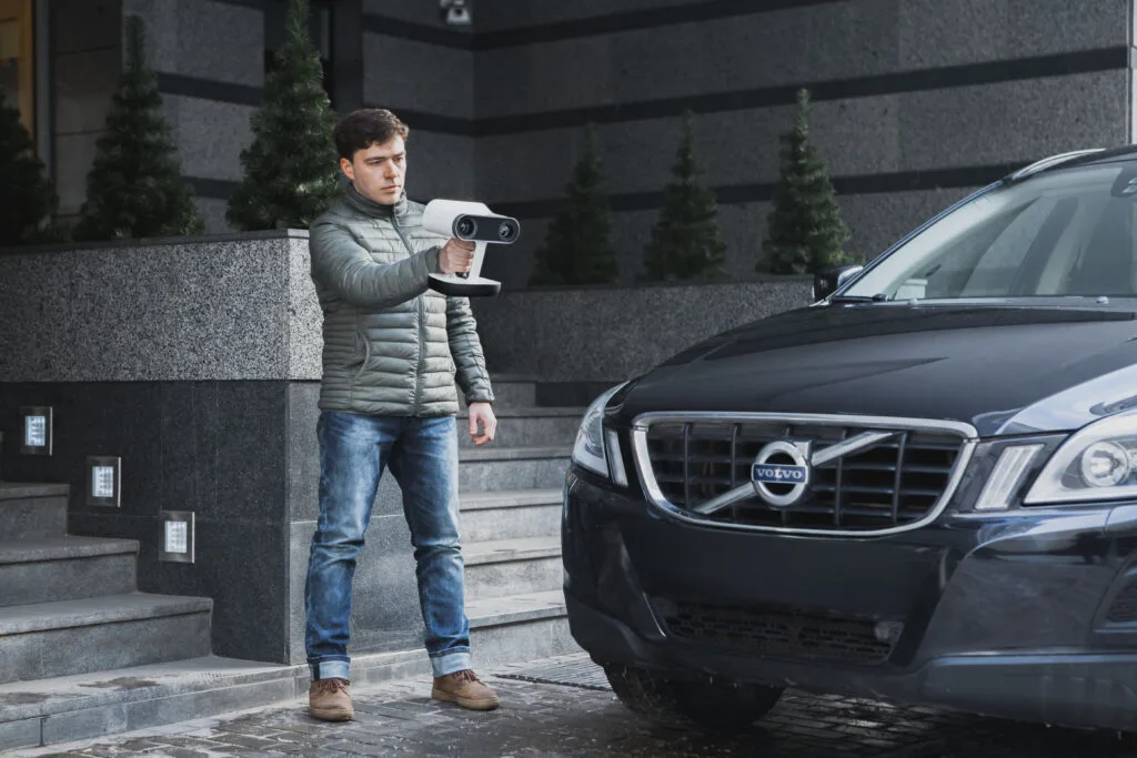
Automotive use cases where Leo is strongest
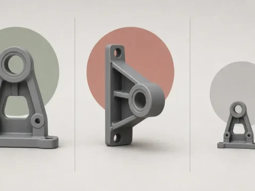
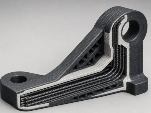
Leo is strongest where the geometry is local, access is awkward, and mobility matters more than formal metrology framing. That includes reverse-engineering reference meshes for brackets, trim, body panels, interior components, and aftermarket fitment work, along with restoration capture and underbody access where moving a standalone handheld scanner around the part is more practical than staging a fixed measurement setup. Its value there is not just nominal resolution; it is the ability to gather usable surface geometry in places that are inconvenient to reach with more rigid workflows. [S1] [S8] [S11]
It is also useful for vehicle documentation and some forensic work. In one Artec case study, a Toyota Highlander exterior was scanned in 32 minutes and processed 90 minutes later, which shows that full exterior capture is feasible as a documentation workflow. SAE’s collision-reconstruction context is broader and older than Leo itself, covering total stations, CMMs, laser scanning, and photogrammetry. That is the right frame for reading Leo in forensics: it can supply geometry quickly, but interpretation, alignment, and validation still belong to the wider reconstruction process. NIST’s discussion of structured-light error sources remains relevant here, especially when the scan may later be measured, compared, or challenged. [S9] [S26] [S17]
Can Artec Leo scan a full car body?
Yes, Leo can scan a full car body as a capture task. Vendor case evidence shows a full Toyota Highlander exterior captured in 32 minutes and processed 90 minutes later. That is proof of practical feasibility, not proof that every full-car scan becomes an inspection-grade dimensional model. [S9]
The real constraints are surface prep, segmentation, alignment quality, and post-processing load. Artec also presents a stripped Toyota Hi-Lux armoring project that took two hours of scanning and five hours of processing, which is a better reminder of what larger assemblies can demand. For bigger HD jobs, Artec recommends 32 GB RAM as a minimum and 64+ GB for larger projects. If you need broader scene context around the vehicle, Ray II is the Artec option aimed at that scale, with vendor-stated range up to 130 m and scan settings of 12 mm, 6 mm, or 3 mm at 10 m depending on mode. That makes it a scene-scale complement, not a substitute for close-detail handheld capture. [S10] [S7] [S12] [S13]
Performance metrics that matter
Accuracy, resolution, and repeatability should not be treated as interchangeable. Accuracy is closeness to the true value, resolution is the level of detail the system can distinguish, and repeatability is how consistently the same setup reproduces a result. For Leo, Artec publishes vendor-stated figures of up to 0.1 mm 3D point accuracy, up to 0.2 mm 3D resolution, and up to 0.1 mm + 0.3 mm/m accuracy over distance. Those are useful specifications, but they are not a blanket guarantee for every surface, part size, or automotive workflow. Repeatability and uncertainty control still have to be managed in practice. [S1] [S24]
Point accuracy and accuracy over distance answer different questions. A locally sharp scan can still accumulate error over longer assemblies, especially when multiple views must be registered into one result. That is why long panels, complete body sides, and assembled vehicle scans depend on overlap and alignment quality as much as on nominal local accuracy. VDI/VDE 2634 Part 3’s multi-view context is especially relevant here because different single images are transformed into a common coordinate system, which is exactly where registration strategy becomes decisive. [S1] [S22]
The standards context also matters. NIST notes that commercial structured-light scanners are often evaluated using VDI/VDE 2634 Part 2 and/or Part 3, but real-world use may deviate from those test conditions. VDI/VDE 2634 Part 2 is for triangulation-based optical 3D measuring systems based on area scanning and explicitly considers external influences such as temperature, humidity, mechanical vibration, environmental lighting conditions, and dust. VDI/VDE 2634 Part 3 addresses multiple-view systems based on area scanning and the transformation of single images into a uniform coordinate system. ISO 10360-8 is narrower than many buyers assume because it is specifically for Cartesian CMMs with optical distance sensors. ISO 10360-13 covers acceptance and reverification tests for optical 3D coordinate measuring systems, but it applies only when surface characteristics such as glossiness and color remain within a cooperative range. None of those standards turns a handheld scanner into a universal inspection instrument by default. [S17] [S21] [S22] [S18] [S19]
Repeatability is the last filter. Structured-light studies emphasize that controlling accuracy and repeatability is essential, and Artec’s own handling guidance keeps Leo within ambient temperatures of +15°C to +35°C, humidity up to 80%, and no condensation. In automotive inspection or deviation mapping, that is a reminder that calibration state, environment, and verification artifacts matter as much as nominal specs when you need defensible results. [S24] [S4] [S17]
Artec-line alternatives for adjacent automotive jobs
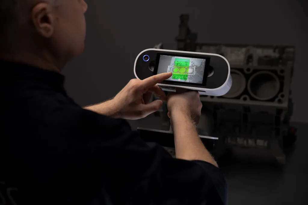
Within Artec’s own line, the job description should drive the choice. Leo remains the flexible close-range option for mobile structured-light capture of panels, interiors, assemblies, and reference geometry. Ray II belongs in scene-scale work, where the surroundings, bay, or accident context matter more than close-detail surface capture. Artec Point sits on the tighter-metrology side of the line, with vendor-stated 3D point accuracy up to 0.02 mm and volumetric accuracy up to 0.015 mm + 0.035 mm/m. [S1] [S12] [S14]
| Job | Best Artec-line fit | Why | Key caveat |
|---|---|---|---|
| Close-range parts, panels, interiors | Leo | Vendor-stated close-range structured-light capture, 0.35 to 1.2 m working distance, and SD/HD workflow suit flexible shop scanning. [S1] | Difficult surfaces and alignment still matter. [S3] [S17] |
| Full accident scene or large environment | Ray II | Vendor-stated range up to 130 m and documented 12 mm, 6 mm, and 3 mm settings at 10 m fit scene-scale capture better than close-detail handheld work. [S12] [S13] | It is not the right tool for fine local part detail. [S13] |
| Tighter metrology on smaller parts | Artec Point | Vendor-stated 0.02 mm point accuracy and volumetric accuracy up to 0.015 mm + 0.035 mm/m suit more inspection-oriented tasks. [S14] | It is a different acquisition style and use case than Leo. [S14] |
| Automated hail or dent detection | None as a default | Published dent-detection work depends on controlled lighting, calibration, alignment, body color, and specialized acquisition logic. [S27] [S28] | No reliable figure found. [S27] [S28] |
A two-scanner Artec workflow is often the cleanest split for complex automotive jobs: Leo for close-range vehicle or part geometry, and Ray II for the surrounding scene or larger spatial context. If the work shifts toward tighter inspection claims on smaller parts, Artec Point is the more appropriate line item. Hail and dent automation should stay conservative because the limiting factor is not only geometry capture, but also controlled illumination, calibration, and algorithm design. [S12] [S14] [S27] [S28]
Limitations: where Artec Leo is not the best fit
Leo is not the best fit when the surface is hostile to structured light. Artec’s own documentation still flags black, transparent, and reflective surfaces as problematic and recommends anti-glare spray, masking tactics, or texture adjustments when needed. NIST’s review reinforces that real-world object characteristics can deviate from test conditions in ways that materially affect scanner performance. [S3] [S17]
It is also not automatically the best 3d scanner for automotive when the job is really a metrology problem. Whole-assembly validity depends on datum strategy, multi-view alignment, and measurement traceability, not just on whether the mesh looks clean. VDI/VDE 2634 puts registration into a common coordinate system at the center of multi-view optical measurement, and ISO 10360-13 keeps optical 3D CMS claims tied to cooperative-surface conditions. Environmental factors such as temperature, humidity, vibration, lighting, and dust still matter. [S22] [S19] [S21] [S17]
Time is the other limitation. Large automotive jobs do not end at capture; they still require cleanup, segmentation, registration review, and often CAD rebuilding afterward. Artec’s HD guidance also makes clear that heavier HD projects raise import and reconstruction costs, with 32 GB RAM as a minimum recommendation and 64+ GB for larger projects. Leo can speed up data collection, but it does not remove the downstream labor of turning scan data into an engineering-ready result. [S8] [S7]
Current research and standards context
Recent automotive inspection work treats 3D scans as deviation fields first and display geometry second. The useful output is the interpretation of where sheet-metal geometry departs from nominal, especially when gap and flushness requirements are involved. That is why a visually complete car-body scan is not automatically a useful inspection result until the alignment and deviation analysis are handled correctly. [S25]
The broader message from research and standards is stable even if product lines change. Structured-light evaluation remains highly sensitive to test method, setup, and uncertainty control, so cross-spec comparisons are fragile when the test regimes are not aligned. NIST’s structured-light error discussion and ISO 10360-13’s cooperative-surface scope both support the same caution: a spec sheet is only the beginning of the measurement conversation, not the end of it. [S24] [S17] [S19]
Practical verdict: when Leo is the right automotive scanner
Leo is a strong answer when the automotive job is close-range, mobile, and driven by reference geometry. In that sense, it can be the best 3d scanner for automotive for body panels, interiors, underbody access, restoration capture, reverse-engineering reference meshes, and fast vehicle documentation. Its vendor-stated local accuracy, working-distance envelope, and standalone workflow support that role, provided the surface and alignment conditions are managed realistically. [S1] [S3] [S8]
It is not the right default for certified inspection, tiny-feature metrology, or automated hail analysis. For tighter metrology on smaller parts, Artec Point is the better fit inside the same product family. For larger scene capture, Ray II belongs in the discussion instead. For dent and hail automation, no reliable figure found supports a Leo-specific threshold or “best hail scanner” claim, and the published literature points instead to specialized lighting and algorithm design. [S14] [S12] [S13] [S27] [S28]
- Use Leo for mobile close-range capture of panels, interiors, underbody regions, and reverse-engineering reference geometry. [S1]
- Use Leo for scan-to-CAD starting data when the deliverable is a mesh-based reference that will be rebuilt and validated later. [S8]
- Use Artec Point, or a comparable metrology-class workflow, when the task is small-part inspection with tighter volumetric expectations. [S14]
- Use Ray II when you need scene-scale coverage, vehicle context, or larger-environment capture beyond Leo’s close-range strength. [S12] [S13]
- Treat full-car Leo scans as feasible capture workflows, not automatic proof of whole-vehicle inspection validity. [S9] [S17]
- Treat hail and dent automation as a specialized discipline requiring controlled illumination and dedicated detection logic. [S27] [S28]
FAQ
These are the practical questions buyers and scanning teams usually ask when deciding whether Leo fits an automotive workflow. The answers below follow the same job-first, standards-aware framing used throughout the article.
Is Artec Leo the best 3D scanner for automotive work?
Conditionally, yes. Leo is strong when the work is close-range, portable, and reference-driven, such as panels, interiors, restoration capture, and reverse-engineering input. Conditionally, no, if “best” means a metrology workflow for tight inspection claims across challenging surfaces or large assemblies. The scanner class has to match the deliverable. [S1] [S3] [S17]
Can Artec Leo scan a full car body?
Yes, as a capture task. Artec case studies report a Toyota Highlander exterior scanned in 32 minutes with processing 90 minutes later, and a stripped Hi-Lux armoring job scanned in two hours with five hours of processing. Those examples show feasibility, but they do not turn every full-body scan into a certified dimensional model. [S9] [S10]
How do you use Artec Leo for automotive 3D scanning without losing tracking?
Keep overlap between passes, stay near the practical 0.5 m stand-off, and use geometry changes such as door gaps, wheel arches, and trim transitions as anchors. Artec’s own guidance also recommends surface prep when black, reflective, or transparent regions interfere with tracking. A customer case study reports capture times dropping from one or two hours to 15 to 30 minutes on some whole-car jobs, but that is anecdotal workflow evidence, not a universal time promise. [S3] [S11]
Is Artec Leo accurate enough for automotive inspection and deviation mapping?
Sometimes, but not as a blanket claim. Leo’s vendor-stated local metrics can support some inspection and deviation-mapping workflows, yet large-assembly results still depend on registration quality, datum strategy, and whether the surface and environment stay within a defensible measurement context. NIST’s structured-light review and VDI/VDE 2634’s multi-view framing are the reason experienced teams separate a good-looking mesh from a valid inspection result. [S1] [S17] [S22]
What do VDI/VDE 2634 and ISO 10360 standards actually mean for handheld 3D scanning?
They tell you what kind of test or measurement claim you are really looking at. ISO 10360-8 is specifically for Cartesian CMMs with optical distance sensors, so it is not a blanket handheld validation standard. ISO 10360-13 is about acceptance and reverification of optical 3D CMS performance and applies only within a cooperative surface range. VDI/VDE 2634 Part 2 and Part 3 frame area-scanning systems, external influences, and multi-view registration into a common coordinate system. [S18] [S19] [S21] [S22]
Is Artec Leo the best 3D scanner for hail damage?
Not on current evidence. Leo may help document hail-damage geometry, but automated dent counting and robust dent recognition are separate technical problems that depend on controlled lighting, calibration, body color, alignment, and specialized algorithms. No reliable figure found supports a Leo-specific dent threshold or a universal “best hail scanner” claim. [S27] [S28]
Related on 3D Mag
- Artec Leo: the best 3D scanner for forensics and crime scene documentation
- Artec Leo: the best 3D scanner for cultural heritage
- Artec Leo Preview: Video, Sample Scan, Specs, Price & Release Date
Sources
- S1 — Artec Leo product page. Page-level URL: https://www.artec3d.com/portable-3d-scanners/artec-leo. Accessed July 28, 2026.
- S3 — Artec Leo documentation: Scan. Page-level URL: https://docs.artec3d.com/leo/scan.html. Accessed July 28, 2026.
- S4 — Artec Leo documentation: Safety & handling. Page-level URL: https://docs.artec3d.com/leo_/1.7/safety-handling.html. Accessed July 28, 2026.
- S5 — Artec Leo documentation: Settings. Page-level URL: https://docs.artec3d.com/leo_/1.7/settings.html. Accessed July 28, 2026.
- S6 — Artec Support Center: HD mode FAQ for Artec Eva and Artec Leo. Page-level URL: https://support.artec3d.com/hc/en-us/articles/360016979000-HD-mode-F-A-Q-for-Artec-Eva-and-Artec-Leo. Accessed July 28, 2026.
- S7 — Artec Support Center: Troubleshooting HD reconstruction performance issues. Page-level URL: https://support.artec3d.com/hc/en-us/articles/360019581980-Troubleshooting-HD-reconstruction-performance-issues. Accessed July 28, 2026.
- S8 — Artec Studio tech specs. Page-level URL: https://www.artec3d.com/3d-software/artec-studio/tech-specs. Accessed July 28, 2026.
- S9 — Origin Forensics case study. Page-level URL: https://www.artec3d.com/cases/origin-forensics. Accessed July 28, 2026.
- S10 — Vehicle armoring case study. Page-level URL: https://www.artec3d.com/cases/vehicle-armoring. Accessed July 28, 2026.
- S11 — Custom Performance Engineering case study. Page-level URL: https://www.artec3d.com/cases/custom-performance-engineering. Accessed July 28, 2026.
- S12 — Artec Ray II product page. Page-level URL: https://www.artec3d.com/portable-3d-scanners/laser-ray. Accessed July 28, 2026.
- S13 — Ray II documentation: scanning settings. Page-level URL: https://docs.artec3d.com/rayII/scanning.html. Accessed July 28, 2026.
- S14 — Artec Point product page. Page-level URL: https://www.artec3d.com/portable-3d-scanners/laser-point. Accessed July 28, 2026.
- S17 — NIST: Sources of Errors in Structured Light 3D Scanners. Page-level URL: https://www.nist.gov/publications/sources-errors-structured-light-3d-scanners. Accessed July 28, 2026.
- S18 — ISO 10360-8:2013 page. Page-level URL: https://www.iso.org/standard/54522.html. Accessed July 28, 2026.
- S19 — ISO 10360-13:2021 page. Page-level URL: https://www.iso.org/standard/74957.html. Accessed July 28, 2026.
- S21 — VDI/VDE 2634 Part 2 contents excerpt. Page-level URL: https://www.vdi.de/fileadmin/pages/vdi_de/redakteure/richtlinien/inhaltsverzeichnisse/1907673.pdf. Accessed July 28, 2026.
- S22 — VDI/VDE 2634 Part 3 scope summary. Page-level URL: https://standards.globalspec.com/std/9914423/vdi-vde-2634-blatt-3. Accessed July 28, 2026.
- S24 — arXiv: uncertainty and repeatability in structured-light 3D scanners. Page-level URL: https://arxiv.org/abs/1910.13199. Accessed July 28, 2026.
- S25 — Interactive quality inspection of deviations in sheet metal assemblies. Page-level URL: https://drops.dagstuhl.de/entities/document/10.4230/OASIcs.iPMVM.2020.6. Accessed July 28, 2026.
- S26 — SAE 2013-01-0784 collision reconstruction paper page. Page-level URL: https://saemobilus.sae.org/papers/accuracy-photo-based-three-dimensional-scanning-collision-reconstruction-using-123d-catch-2013-01-0784. Accessed July 28, 2026.
- S27 — CMMS 2024 dent detection paper. Page-level URL: https://www.cmms.agh.edu.pl/public_repo/2024_3_0836.pdf. Accessed July 28, 2026.
- S28 — Georgia Tech repository dent recognition study. Page-level URL: https://repository.gatech.edu/entities/publication/498c58c9-78ec-4537-8f9d-7449f06217ee. Accessed July 28, 2026.