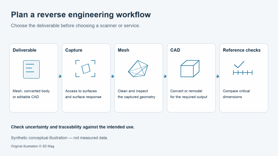
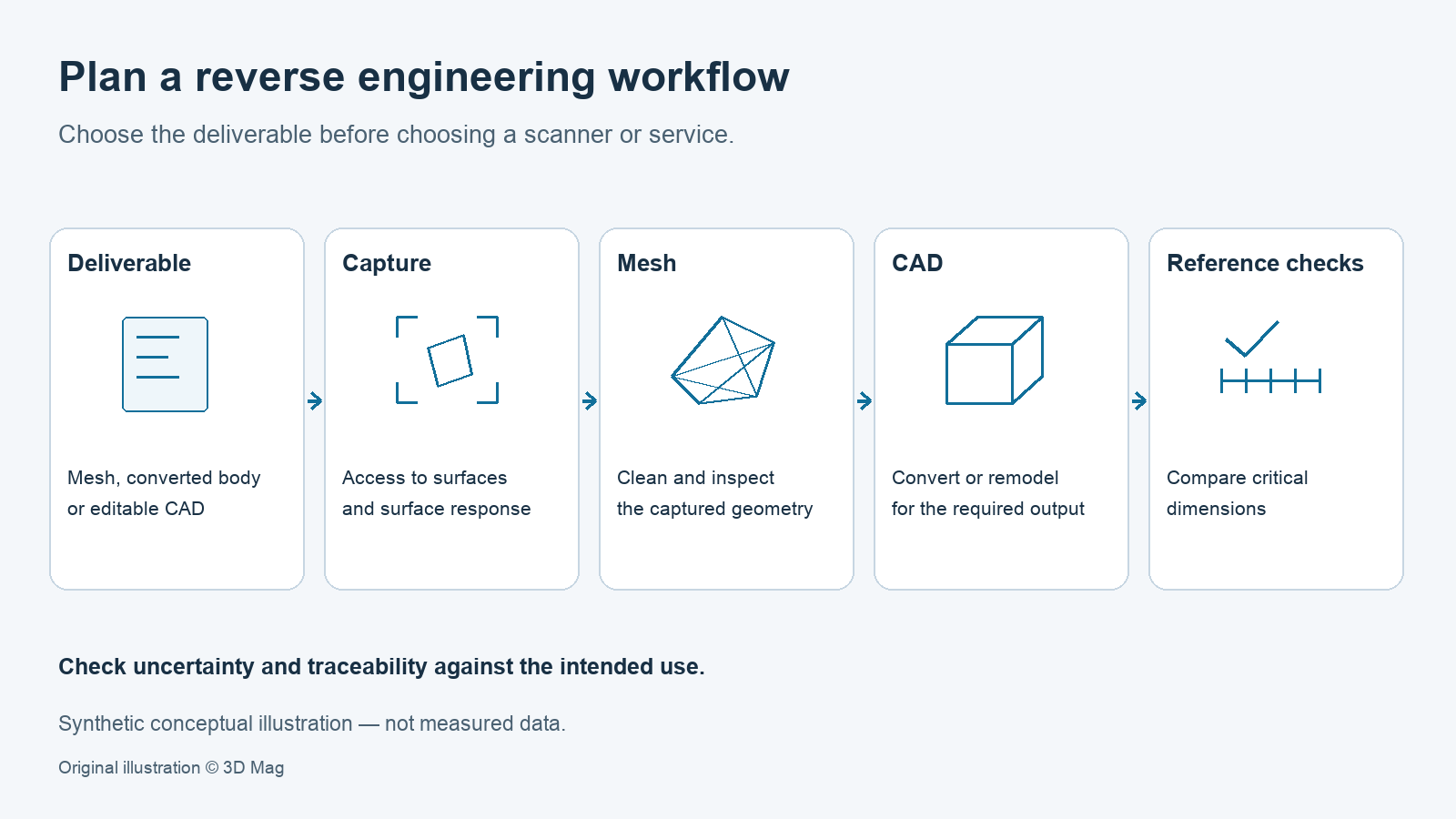

To choose a 3D scanner for reverse engineering, start with the part, not a scanner model. First decide which digital deliverable you need: a mesh, a surface or solid body converted from that mesh, or an editable CAD reconstruction. Then list the dimensions that matter and the measurement confidence they require. Only then judge whether a scanner or scanning service can capture the geometry and surfaces involved. This article names no hardware winner, because the right device depends on your specific part and job.
Start with the CAD deliverable and the dimensions that matter
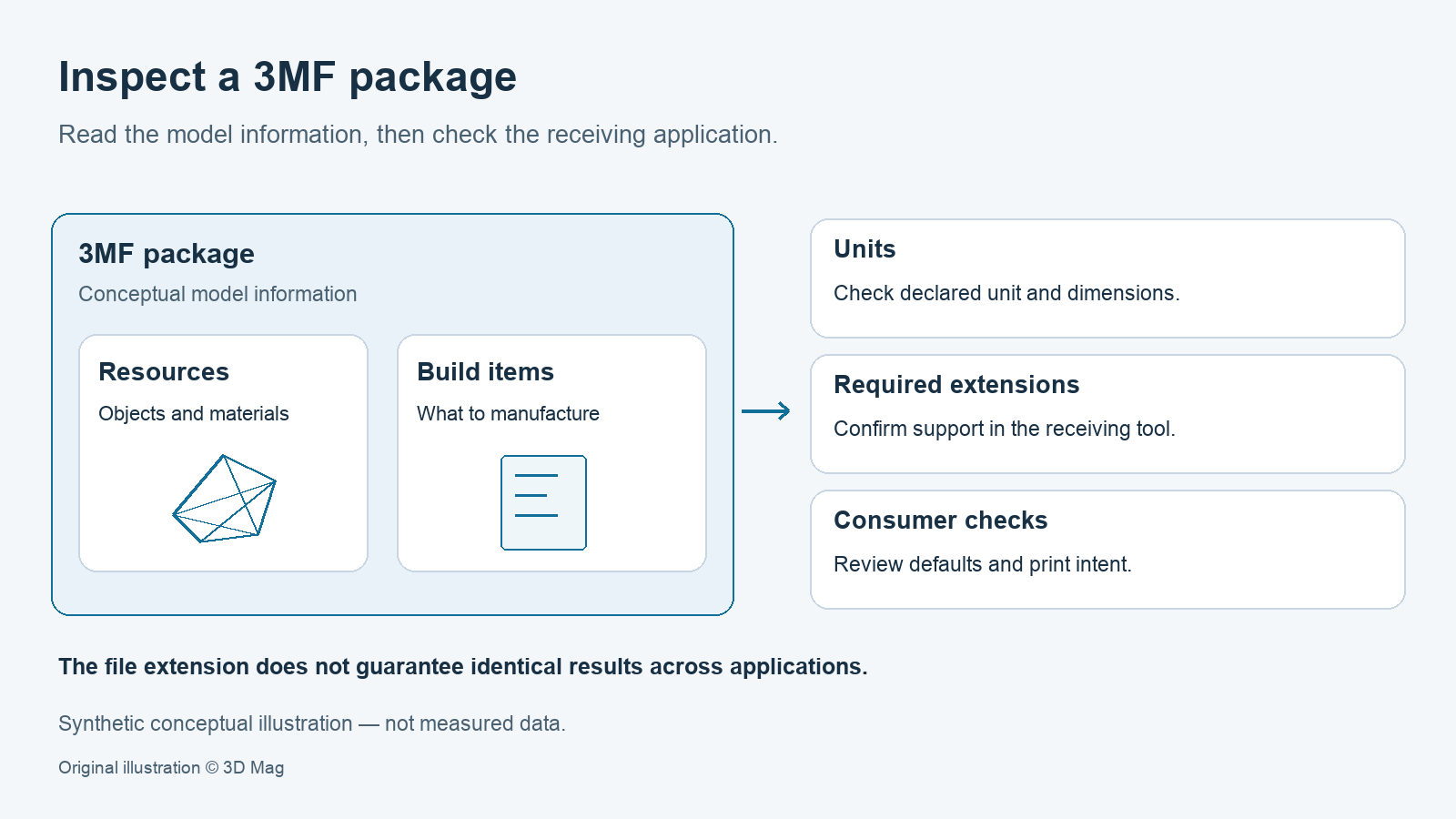
If your scan data arrives as a mesh body, CAD software can convert it into other body types. According to the Autodesk Fusion documentation, the Convert Mesh tool converts a mesh body to a solid or surface body.
Conversion is not the same as recovering how the part was originally designed. In Fusion, the Parametric operation keeps upstream relationships in the timeline, and the Base Feature operation does not (Autodesk Fusion documentation). Those are relationships inside the new model’s timeline, not the original designer’s intent, feature logic or tolerances. If you need an editable model that captures design intent, plan for separate modelling work.
A decision table: requirements and questions, not rankings
| Requirement | Question to answer before choosing hardware or a service | Why it matters |
|---|---|---|
| Output type | Do you need a mesh, a converted surface/solid, or an editable reconstruction? | Planning guidance: decide this first, because it determines what the capture must deliver. |
| Geometry and visible access | Can every surface you need actually be seen during capture? | Surfaces that are not captured can leave openings. In Fusion, a watertight mesh converts to a solid body and a non-watertight mesh converts to a surface body. |
| Surface response | Are any surfaces dark, reflective, transparent, translucent or lacking solid structure? | An Artec support article lists these as potentially challenging for optical scanners. Check the documentation for the exact device you are considering. |
| Measurement confidence | Which dimensions are critical, and what stated uncertainty do they need? | The VIM defines uncertainty as a non-negative parameter characterizing the dispersion of values attributed to a measurand, based on the information used. |
Difficult surfaces: what one manufacturer documents
Artec’s support article, dated March 19, 2020, states that for optical scanners it could be a challenge to scan dark (black), reflective, transparent, translucent materials, or surfaces without a solid structure (Artec support article). That is one manufacturer’s guidance; this article does not claim that every optical scanner has identical restrictions.
The same article says its list is not exclusive and that some difficult surfaces might fit into several categories (Artec support article).
For difficult surfaces, Artec suggests using a scanning spray or another suitable coating and adjusting scanning angle and distance (Artec support article). Whether a coating is compatible with your part’s material, and how to use it safely, is a question for the coating’s and the scanner’s own instructions. This article gives no recipe and no compatibility guarantee.
What conversion changes
Fusion documents several conversion methods (Autodesk Fusion documentation):
- Faceted converts individual faces on the mesh body to individual faces on the new solid or surface body.
- Prismatic merges groups of faces in prismatic features into single faces, using face groups to infer prismatic features.
- Organic converts the mesh body to an organically shaped solid or surface body. The documentation states that this feature is part of an extension.
Fusion’s tips recommend Organic for geometry originally created from scan data or organic modelling tools, and Prismatic for geometry originally created with solid or surface modelling tools (Autodesk Fusion documentation). In these tips the deciding factor is how the input geometry was created, not simply what the physical object looks like.
The documentation also explains why you sometimes get a surface instead of a solid. A watertight mesh converts to a solid body, a non-watertight mesh converts to a surface body, and surface tools such as Stitch and Patch can turn a surface body into a solid (Autodesk Fusion documentation). These statements reflect the page as accessed on October 7, 2026, which states no software version. Licensing and availability of the extension are not covered here.
Accuracy, uncertainty and traceability as planning requirements
The term “accuracy” is used in more than one sense, so it helps to separate it from uncertainty and traceability using the international metrology vocabulary (VIM).
The VIM defines measurement accuracy as the closeness of agreement between a measured quantity value and a true quantity value of a measurand. It adds that accuracy is not a quantity and is not given a numerical quantity value. That does not make every published accuracy figure meaningless; it means you should ask what the figure describes.
A BIPM annotation to the same entry warns that care must be taken in explaining in which sense the term “measurement accuracy” is being used (VIM).
As an editorial caution, treat any published resolution figure as a separate specification, not as a statement of accuracy.
According to the VIM, measurement uncertainty includes components arising from systematic effects. On this article’s reading of that note, uncertainty is not limited to random scatter between repeated measurements.
The VIM defines metrological traceability as a property of a measurement result that relates the result to a reference through a documented unbroken chain of calibrations, each contributing to the measurement uncertainty.
Traceability has limits. The VIM notes that it does not ensure that the measurement uncertainty is adequate for a given purpose, or that there is an absence of mistakes (VIM). A calibration chain is necessary evidence, not a pass mark for your part.
A proposed reverse engineering workflow
The steps below are suggested workflow guidance. They are not a test that 3D Mag performed.
- Fix the deliverable. Choose mesh only, converted surface/solid, or editable reconstruction. List the critical dimensions and the uncertainty they require.
- Assess the part. Check geometry, visible access and surface response against the documentation for the exact candidate device or service. If you consider a coating, follow the product’s own compatibility and safety instructions.
- Capture, then clean the mesh. If you need a solid, aim for a watertight mesh.
- Reconstruct in CAD. Choose the conversion method according to how the input geometry originated, or remodel features where you need editable design intent.
- Compare against references. Check the result against reference dimensions that have a stated uncertainty and documented traceability. Record in which sense “accuracy” is being used.
Checks before accepting the model
This is a proposed checklist, not a reported test:
- Is the result a solid or a surface body, and is that what the deliverable requires?
- Does the conversion method suit the input geometry’s origin?
- Do the reference dimensions come with a stated uncertainty and evidence of traceability?
- Is that uncertainty adequate for the critical dimensions, judged separately from traceability itself?
- Does every quoted “accuracy” state what was measured and under which conditions?
FAQ
Is converting a scan mesh to a solid the same as recovering the original CAD design? No. Conversion produces a solid or surface body. Fusion’s Parametric option keeps timeline relationships, which is not the same as the original designer’s intent, features or tolerances.
Why did my conversion produce a surface instead of a solid? Per Autodesk’s documentation, a mesh that is not watertight converts to a surface body. Stitch and Patch can then help build a solid.
Can one accuracy number tell me whether a scanner fits my part? Not by itself. Ask what was measured, under which conditions, and with what stated uncertainty.
Does traceable calibration guarantee the result is good enough? No. Traceability does not by itself make the uncertainty adequate for your purpose or rule out mistakes.
Do all optical scanners struggle with the same surfaces? This article does not claim that. Check the documentation for the exact device you are considering.
Sources
This explainer is based on the cited metrology vocabulary and software and manufacturer documentation; 3D Mag did not conduct hands-on testing. Publisher sponsorship.