
Summary
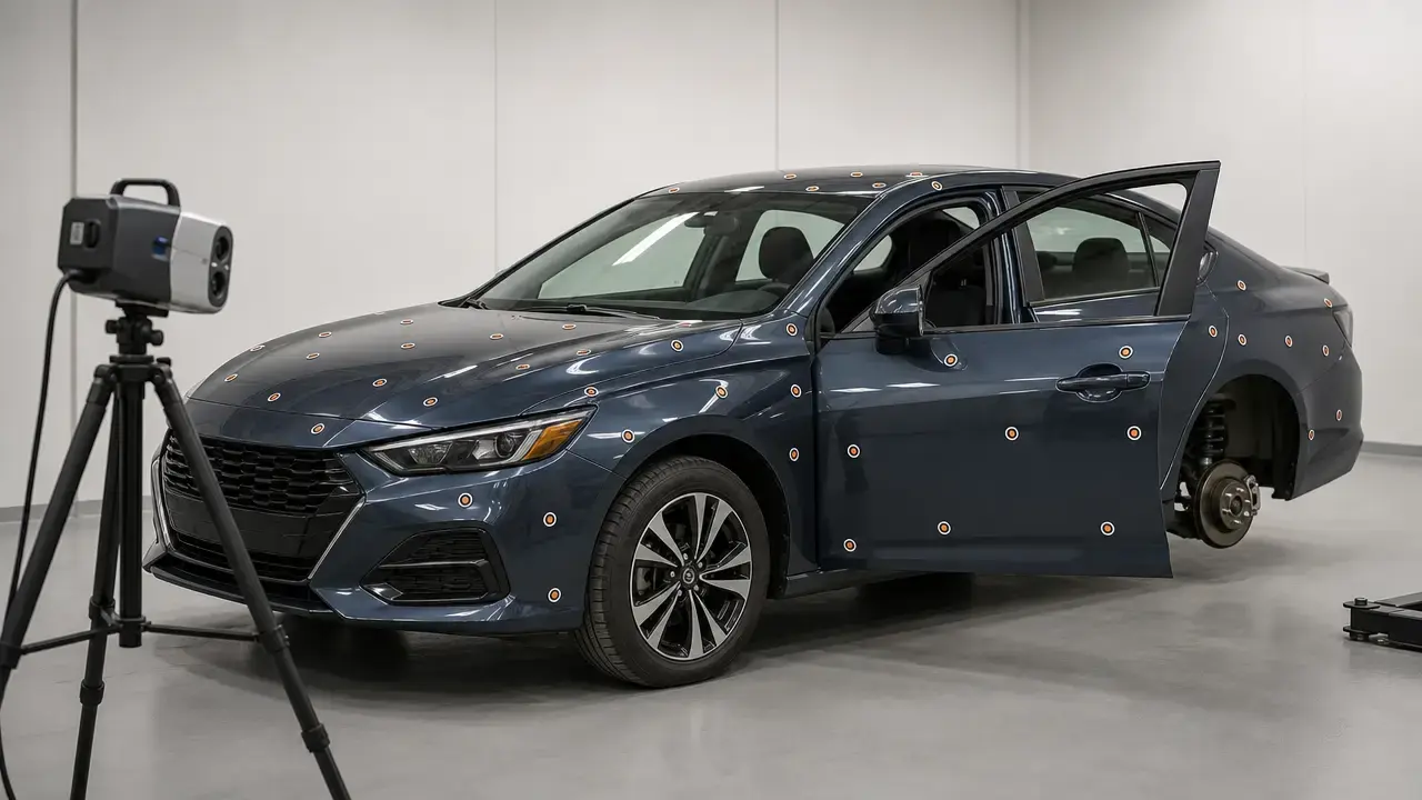
Car 3d scanning is usually done for one of three outcomes: a visual shape model, dimensional inspection, or CAD-ready surfacing. Those are different jobs. A point cloud or mesh can be enough for documentation, while scan-to-CAD usually needs cleanup, feature interpretation, and surface rebuilding before the result is useful for engineering or manufacturing. [1] [19]
The practical workflow is more demanding than most demos suggest. A vehicle combines glossy paint, glass, chrome, black trim, large smooth panels, hidden recesses, and repeated shapes, so capture quality depends on surface behavior, access, registration, and verification, not just on the scanner head. ISO 10360-13 is a useful reality check here: its optical 3D CMS test scope applies only when surface characteristics such as glossiness and colour are restricted and within a cooperative range. That is why whole-car metrology claims should be treated as conditional, not universal. [1]
| Deliverable reality check | What you get | Typical file(s) | What you still must do |
|---|---|---|---|
| Visual mesh | Readable digital shape for viewing or context | STL, OBJ, PLY | Clean noise, manage holes, decide whether texture matters |
| Dimensional inspection | Registered geometry for comparison to nominal data | Point cloud, mesh, inspection report | Establish reference frame, verify scale, compare to CAD or hard references |
| CAD-ready surfacing | Rebuilt surfaces or features intended for downstream design | NURBS, STEP, IGES, native CAD | Rebuild features, control continuity, validate dimensions |
Why cars are hard to scan
Cars are difficult optical targets because the surface itself is part of the measurement problem. ISO 10360-13 does not treat optical 3D systems as universally applicable; it limits applicability to objects whose surface characteristics stay within a cooperative range. A typical vehicle mixes glossy paint, clear glass, dark trim, chrome, and abrupt material changes, so return quality and edge detection can vary across the same body shell. [1]
- glossy paint
- glass
- chrome
- black trim
- broad smooth panels
- occlusion in wheel wells and underbody
- repeated shapes
Geometry adds another layer of difficulty. Long door skins, quarter panels, roofs, and hoods may offer too little distinctive geometry for easy alignment, while repeated left-right features can create more than one plausible registration solution. On a full vehicle, that often shows up not as obvious failure but as quiet drift, stacked alignment error, or local warping that only becomes clear when you check a known dimension or revisit an earlier area. Registration and stitching are documented uncertainty contributors in optical workflows, so overlap alone is not enough. [6] [7]
Access is the other half of the problem. Wheel wells, underbody zones, mirror pockets, window frames, engine bays, and cabin edges create occlusion, so a simple walkaround rarely captures everything needed. The result is uneven data density, awkward setup changes, and more manual repair later. For scan-to-CAD work, those holes and boundary mismatches matter because they increase how much interpretation is required before the data becomes usable design geometry. [6] [19]
Scanner approaches for cars
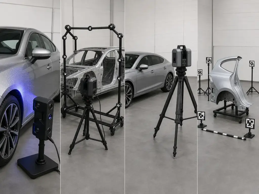
Choosing a 3d scanner for cars is mostly about matching the job to the measurement volume. The main questions are whether you need close-range surface detail, larger coordinated volume, scene context, or a controlled photographic workflow, and how traceable the result needs to be. Manufacturer-stated specs are useful examples, but standards and scientific papers define scope more carefully than product pages do. [4] [5]
| Scanner approach | Best for (car use) | Watch-outs (car-specific) | Evidence to cite |
|---|---|---|---|
| Handheld laser / structured light | Body panels, interiors, trim, reverse engineering, scan-to-CAD inputs | Reflective surfaces, short working distance, drift across long paths, target strategy, local vs volumetric performance | HandySCAN specs [10]; Artec Leo specs [12] |
| Tracker-based optical CMM scanner | Assemblies, larger vehicle sections, inspection where coordinated volume matters | Line-of-sight, setup control, measurement volume dominates the trust you can place in the result | MetraSCAN specs [11] |
| TLS / LiDAR | Crash scene context, large vehicles, spatial documentation, shop-floor or site context | Range-dependent accuracy, small feature fidelity, multiple setups and registration | ASTM scope [4]; NIST TLS context [5]; Leica specs [14] |
| Photogrammetry | Visual models and texture, or dimensional support when calibrated with targets and scale bars | Method-dependent results, glossy panels, need for scale control and careful camera placement | SAE vehicular photogrammetry example [8] |
Evidence types are not equal. ISO and ASTM define what a standard covers. NIST discusses uncertainty and traceability. Peer-reviewed or institutional studies show how methods behave under defined conditions. Manufacturer pages show example capabilities under their own stated conditions. Mixing those categories without labeling them is how scanner comparisons become misleading. [4] [5] [8] [10] [11] [12] [14]
A few manufacturer-stated examples show the tradeoff clearly. Creaform’s HandySCAN BLACK Elite lists 0.025 mm accuracy, 0.020 mm + 0.040 mm/m volumetric accuracy, 1,300,000 measurements/s, a 200 to 450 mm working distance, and a recommended part size of 0.05-4 m. Creaform’s MetraSCAN BLACK+ Elite lists 0.025 mm accuracy and volumetric accuracy of 0.064 mm at 9.1 m³ or 0.075 mm at 16.6 m³, with C-Track working distance up to 4.2 m and recommended part size of 0.2-6 m. Artec Leo lists up to 0.1 mm point accuracy, up to 0.2 mm resolution, and 0.35-1.2 m working distance. Leica’s RTC360 is a different class entirely, with 0.5-130 m range and 3D point accuracy of 1.9 mm at 10 m, 2.9 mm at 20 m, and 5.3 mm at 40 m. [10] [11] [12] [14]
Scanner choice is not the whole requirement. Some systems reduce field hardware during capture, but processing still needs compute. Artec Leo’s official PDF says scanning requires no computer, while recommended processing calls for an Intel Core i7 or i9, 64+ GB RAM, and an NVIDIA GPU with 8+ GB VRAM; its HD minimum is 32 GB RAM and at least 4 GB VRAM. [13]
Technical principles that matter for vehicle capture
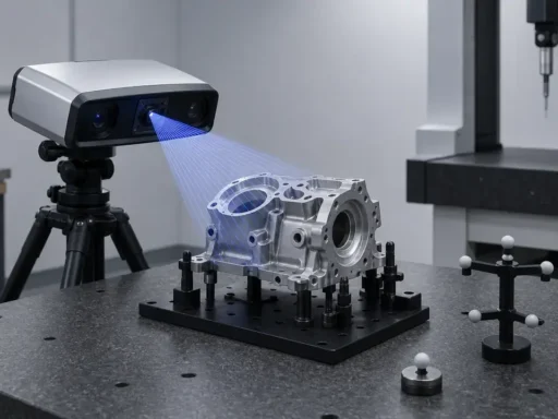
For handheld laser and structured light 3d scanning, the practical principle is triangulation. The system projects light, observes it from another viewpoint, and computes surface position from the geometry between projector, cameras, and object. That works well on close-range vehicle parts, but only inside a limited operating window. Creaform’s HandySCAN BLACK Elite lists a 200 to 450 mm working distance, while Artec Leo lists 0.35 to 1.2 m. On a car, that makes path planning and view angle part of the measurement, not just operator comfort. [10] [12]
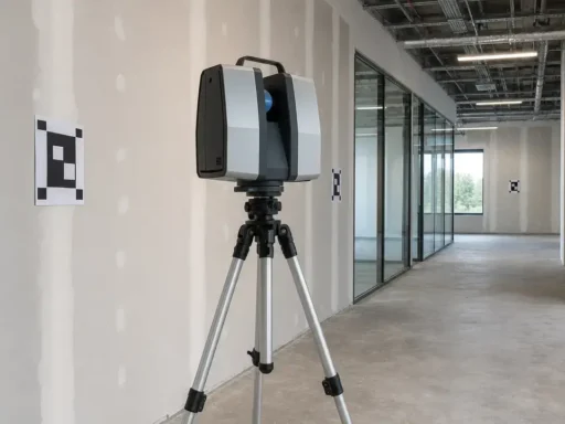
TLS and similar LiDAR systems solve a different problem. ASTM E2938-15(2023) covers laser-based, scanning, time-of-flight 3D imaging systems in the medium range, meaning systems that operate within at least part of 2 to 150 m. That scope is useful for scene-scale or vehicle-context capture, but it should not be used to market handheld triangulation performance. The classes are measuring different volumes, at different point spacings, and under different uncertainty regimes. [4] [5] [14]
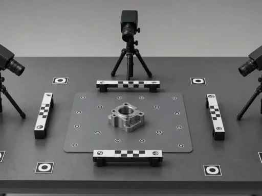
Photogrammetry uses overlapping images, camera calibration, and scale control to recover 3D geometry. The key distinction is between casual image-based modeling and controlled dimensional work. In the SAE vehicular example, the method used a field-calibrated DSLR with a fixed 20 mm lens, retroreflective targets, a CNC-machined scale bar, and eight photographs; reported average residuals were 1.7 mm versus total station points and 1.2 mm versus FaroArm points. That shows calibrated photogrammetry can support dimensions, but only when the workflow is controlled. [8]
Car 3D scanning workflow: from vehicle to usable data
Car 3d scanning gets easier once the deliverable and tolerance are fixed before capture starts. A visual mesh can tolerate more cleanup and more inferred closure than an inspection workflow. A scan-to-CAD job needs more discipline, because the mesh is only the raw geometric evidence for later surfacing or feature reconstruction. For whole-car work, no reliable universal figure found is the honest answer on accuracy, because surface conditions and multi-setup registration vary too much from vehicle to vehicle. [1] [6] [7] [19]
Access planning
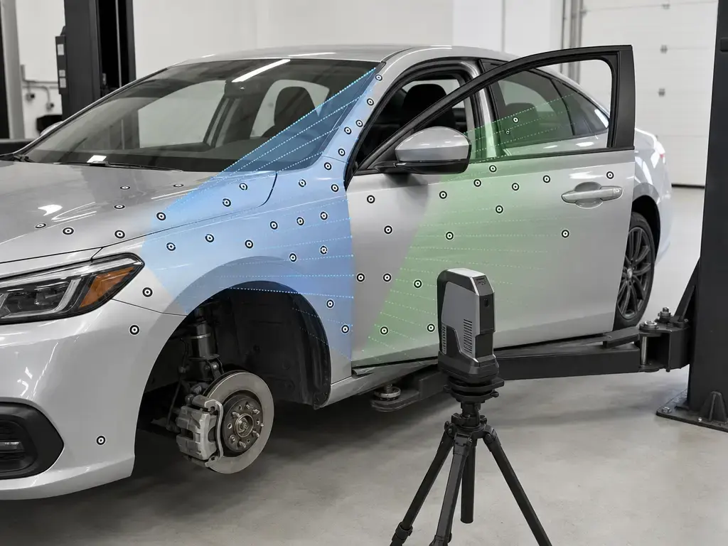
Before capture, decide how the vehicle will be presented. Doors open or closed change continuity through jambs and into the cabin. Ride height and suspension state affect wheel-arch and underbody geometry. Wheel removal changes access, but it also changes the condition being recorded. Lifting or jacking adds underside visibility, but it also creates another setup state that must be merged back into the main datum structure. If the car moves between setups, you need a datum transfer plan before you start. [6] [17]
- Doors open or closed state
- Suspension state
- Wheel removal if wheel wells or liners matter
- Lift or jack implications for underside access and setup merging
- Datum transfer between setups by targets, scale bars, or tracker control
Workflow checklist
- Define deliverable and tolerance needs.
- Wash/clean and stabilize vehicle.
- Remove or mask unwanted objects.
- Decide whether spray, markers, or targets are acceptable.
- Plan scan sections and access around the car.
- Capture overlapping passes.
- Register and align scans.
- Clean noise and fill only justified holes.
- Verify scale/dimensions against references.
- Export mesh, report, or CAD-ready data.
Drift, scale control, and registration strategy
Registration is where many full-vehicle jobs turn into measurement projects instead of simple capture projects. NIST’s stitching paper makes the issue explicit: long reference lengths are hard, so adjoining or overlapping shorter measurements can accumulate stitching errors, and registration can be used to construct longer stitched lengths for evaluation. The UTK structured-light paper also points to point cloud stitching and registration as primary uncertainty contributors. On a vehicle, that means a good-looking merged model can still be dimensionally weak if the reference structure was weak. [6] [7]
It helps to separate three ideas. Local frame performance is what a close-range scanner spec often describes. Volumetric accuracy is what a larger coordinated system claims across a stated measurement volume. End-to-end project uncertainty includes capture, sectioning, scaling, alignment, cleanup, and any manual editing before export. Those ideas are related, but they are not interchangeable. [10] [11] [12] [14]
- Use a reference strategy such as known lengths, a scale bar, tracker control, or a photogrammetry control network.
- Think in loop closures: return to known geometry or targets instead of only marching forward.
- Maintain target continuity across occluded transitions such as wheel wells, underbody entries, and cabin openings.
- Perform independent checks with known hardpoints, a steel rule, or other traceable references when tolerances matter.
- Document when spray, lighting, or setup state changed, because that changes the measurement stack.
- Keep section boundaries visible during QC so drift is not hidden by cleanup.
Performance metrics: accuracy, repeatability, resolution, volumetric accuracy, and uncertainty
Performance language gets mixed up quickly in car scanning. A dense mesh can look impressive without being dimensionally trustworthy, and a scanner can sample fine local detail without preserving vehicle-scale distances after many merged setups. The useful question is not which device has the smallest headline number, but which number describes the part of the job you actually care about. ISO 10360-13 exists precisely because metrology claims need defined tests and defined scope. [1] [5]
| Metric | What it means | Where it appears | Common misuse | How to sanity-check on a car |
|---|---|---|---|---|
| Accuracy | Closeness to a known reference | Standards, datasheets, reports | Treated as one universal number | Compare to known dimensions or reference artifacts |
| Repeatability / precision | How consistently the system returns the same result | Repeat studies, operator comparisons | Confused with accuracy | Re-scan the same panel or target set |
| Resolution / point spacing | Smallest detail sampled or represented | Scanner specs, mesh settings | Assumed to equal accuracy | Check whether real edges, seams, and gaps are preserved |
| Volumetric accuracy | Performance across a stated measurement volume | Large-part system specs | Used as if it were local panel accuracy | Check the stated distance or volume conditions |
| End-to-end uncertainty | Combined effect of capture, scaling, alignment, cleanup, and export | Inspection plans, measurement strategy | Ignored after the merge step | Trace the workflow from capture to final file |
The standards picture matters because scope matters. ISO 10360-13:2021 is Edition 1, published in September 2021, and listed at 52 pages on the ISO page. DIN EN ISO 10360-13:2023-11 is the current DIN adoption listing, at 74 pages. By contrast, VDI/VDE 2634 Blatt 3:2008-12 is listed by DIN Media as withdrawn, 20 pages, with a note recommending DIN EN ISO 10360-13:2023-11 in lieu of it. That matters because some live manufacturer spec pages still cite VDI/VDE 2634 Part 3 in their acceptance-test notes. [1] [2] [3] [10] [11]
Study design changes interpretation too. The UTK structured-light study used 5 repeated scans at 15 measurement positions and generated 50 datasets, which is a reminder that measurement position and registration strategy are part of the result. Manufacturer examples then illustrate class differences: HandySCAN BLACK Elite lists 0.025 mm accuracy and 0.020 mm + 0.040 mm/m volumetric accuracy; MetraSCAN BLACK+ Elite lists 0.064 mm at 9.1 m³ and 0.075 mm at 16.6 m³; Artec Leo lists up to 0.1 mm point accuracy and up to 0.1 mm + 0.3 mm/m over distance; Leica RTC360 lists 3/6/12 mm resolution at 10 m and 3D point accuracy that changes with range. Those numbers answer different questions. [7] [10] [11] [12] [14]
How long does full vehicle 3D scanning take?
For full vehicle 3d scanning, case examples are more honest than averages. Artec’s Mercedes E350 model page says the sprayed-down body was scanned in 20 minutes and processed in 90 minutes. Artec’s Origin Forensics case says a Toyota Highlander exterior demo took 32 minutes to scan and 90 minutes to process. Creaform’s Rob Dahm workflow blog says the whole experience took about 2 hours and described positioning targets spaced about 4 to 5 inches apart. These are useful reference points, but they are manufacturer case examples, not universal job times. [15] [16] [17]
The hidden time is usually in preparation, access, target placement, cleanup, verification, and deliverable choice. Interior work, underside work, or wheel-well coverage increases repositioning and merging effort. Higher mesh density increases processing time, and inspection workflows add reporting and dimension checks before the data can be trusted. If the deliverable is scan-to-CAD rather than a visual mesh, the surfacing stage can take longer than capture itself. In the Origin Forensics example, the chosen output for a vehicle was still managed as roughly 2 to 5 million triangles with an 8K texture map, which shows how deliverable choices change workload. [16] [19]
Surface prep, scan sprays, targets, and tracking
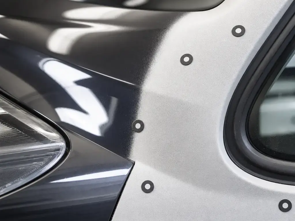
Surface prep is conditional, not automatic. If the body finish already behaves well enough for the chosen scanner, coating may be unnecessary. If the finish is glossy, transparent, or strongly reflective, prep can become necessary because the optical system cannot reliably recover geometry from unstable returns. One manufacturer workflow example describes spraying a very thin white coating on windows and lights before scanning, but that remains a workflow example, not a rule for every car or every finish. [17]
Spray claims need extra care because they sit inside the measurement stack. AESUB yellow’s Rev. 01/2023 technical datasheet says material compatibility cannot be guaranteed for specific applications, the user must check compatibility before use, and the product contains solvents. It also warns that wax-like surfaces and simple 1K coatings should be tested thoroughly beforehand. The same datasheet says a layer thickness below 2 µm is possible with proper compressed-air airbrush application. That is useful context, but it does not justify calling any scan spray universally paint-safe or residue-safe. Use a test patch and owner approval before coating a vehicle surface. [9]
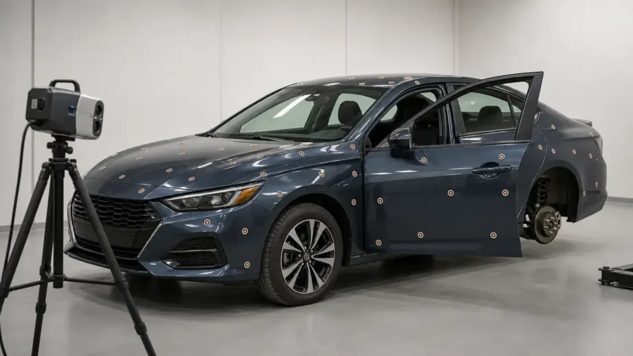
Targets and tracking also need to match the geometry. Smooth panels and repeated shapes often benefit from markers because they give the software reliable references that the body itself may not provide. Tracker-supported systems add an external coordinate reference, which changes how drift is managed across larger volumes. The practical rule is simple: use markers, targets, or external control when the geometry is not doing enough work on its own, and document what was used so later verification makes sense. [6] [7] [11] [17]
- Use spray only when surface condition blocks capture and finish safety is approved.
- Apply markers per workflow and do not decorate randomly.
- Preserve overlap and revisit references to reduce drift.
- Include independent scale checks where accuracy matters.
- Document coating, targets, and lighting changes.
Point cloud vs mesh vs CAD
On a vehicle, the point cloud is the raw measured evidence, the mesh is a connected approximation of that evidence, and CAD is the editable model needed when continuity, feature control, and downstream modification matter. That difference becomes obvious at shut lines, panel gaps, flange transitions, and symmetric surfaces, where the scan may record what exists but the engineering model still has to decide what should remain measured, what should be rebuilt, and what should become an analytic feature. [18] [19]
STL and OBJ can carry useful shape data, but they are not the same thing as editable or machinable CAD. The J-STAGE car-body reverse-engineering paper states that STL triangle data could not be used directly for CNC fine machining and was converted into a CATIA V5 CAD model. That is why scan-to-CAD is a process, not a file export checkbox. [19]
Applications
Car body 3d scanning is useful wherever real geometry must be captured before design or fit-up begins. That includes custom body kits, restoration, obsolete parts, packaging components, roll-cage and interior fitting, and vendor-neutral reverse-engineering inputs. In these jobs, the right deliverable may be a mesh for context, a point cloud for inspection, or rebuilt CAD for design work. [19]
The same geometry can support damage documentation, QA, and digital archiving, but the intended use still controls the workflow. In the Origin Forensics case, vehicle outputs were managed at about 2 to 5 million triangles with an 8K texture map, which fit documentation and visualization goals in that case-study context. That does not mean every automotive scan should be textured, meshed, or prepared the same way. [16]
Limitations and failure modes
Most vehicle scanning failures are ordinary, not exotic. Occlusion leaves missing data in wheel wells, underbody areas, mirrors, and cabin edges. Drift builds when long capture paths are stitched together without strong external references. NIST’s stitching work explains why adjoining or overlapping short lengths can stack error, and structured-light literature separately flags stitching and registration as uncertainty contributors. A complete-looking vehicle viewer file can still fail a dimensional check. [6] [7]
Post-processing can create its own problems. Over-smoothing can erase break lines and feature transitions. Unjustified hole filling can invent geometry that was never measured. Decimation can remove detail that later matters for panel fit or surfacing. Texture can also create false confidence: a convincing shaded model can hide weak geometry underneath. Dense output does not guarantee trustworthy dimensions. [16] [19]
Physical vehicle behavior matters too. Non-rigid trim, moving panels, open-versus-closed door states, and suspension changes can make two passes disagree even if the scanner itself is stable. Reflective and transparent areas remain difficult because they challenge both return quality and tracking stability. The hard part is not just collecting points; it is deciding which parts of the vehicle are fixed, visible, and trustworthy enough to serve as measurement references. [1] [6] [7]
A short historical note on automotive scan-to-surface workflows
This workflow is not new. A 2004 automotive example by Sansoni and Docchio described acquisition, point cloud alignment, triangle model definition, NURBS creation, STL generation, and a scaled Ferrari 250MM replica. The modern difference is speed, portability, and software convenience, not the underlying logic: capture, align, verify, rebuild where needed, and export something the downstream process can actually use. [18]
Standards and research: what actually limits accuracy on a full vehicle scan
The first limitation is surface condition. ISO 10360-13:2021 anchors acceptance and reverification tests for optical 3D CMS, but it does so only for objects whose surface characteristics are restricted and within a cooperative range. A painted vehicle with dark trim, chrome, and transparent sections is therefore not a universal standards-friendly target. That is why no reliable universal figure found is the defensible whole-car answer: the measurement context changes from panel to panel. [1]
The second limitation is registration across scale. ASTM E2938 frames medium-range time-of-flight systems, not handheld triangulation scanners, while NIST emphasizes error sources, documentary standards, and metrological traceability rather than one winner number. NIST’s stitching paper and the UTK structured-light study reinforce the same practical point: alignment strategy affects the result. If you want trustworthy vehicle data, control the surface, control the reference network, and verify scale independently before believing the merged model. [4] [5] [6] [7]
Conclusion: what car 3D scanning actually takes
Car 3d scanning is a measurement workflow, not a magic CAD button. The deliverable comes first, and the capture plan only makes sense after that. [1] [19]
What usually works is straightforward: choose the scanner class that matches the scale, treat surface prep as a conditional tool, manage registration deliberately, verify dimensions against references, and accept the deliverable the data can honestly support. For car body 3d scanning, that usually means a point cloud, mesh, inspection dataset, or rebuilt CAD model with known limits rather than a promise of universal whole-car accuracy. [6] [7] [19]
FAQ
What does it take to 3D scan a car?
It takes more than walking around the body with a scanner. You need to define the deliverable, choose a scanner class that fits the scale, plan access to the exterior, interior, wheel wells, or underside, decide whether spray or targets are acceptable, capture with enough overlap, register the sections, verify scale, and then export the right output. In other words, car 3d scanning is capture plus registration plus verification, not capture alone. [1] [6] [7] [19]
How long does full vehicle 3D scanning take in practice?
Use case examples, not averages. Artec’s Mercedes E350 example lists 20 minutes of scanning and 90 minutes of processing for a sprayed-down body. Artec’s Toyota Highlander exterior demo lists 32 minutes of scanning and 90 minutes of processing. Creaform’s Rob Dahm workflow article describes the whole experience as about 2 hours, with targets about 4 to 5 inches apart. Interior scope, underside access, higher mesh density, inspection reporting, and surfacing work can all extend the job. [15] [16] [17]
What 3D scanner for cars is best for scanning a car body?
There is no universal best 3d scanner for cars. Handheld laser or structured-light systems are often the practical choice for close-range panels and reverse engineering. Tracker-supported systems help when coordinated volume matters across larger sections. TLS is more appropriate for scene context and larger spatial documentation. Photogrammetry can work well either for visual models or for dimensional support when the workflow is calibrated with targets and a scale bar. The right choice follows deliverable, tolerance, surface condition, and measurement volume. [4] [5] [8] [10] [11] [12] [14]
How accurate is car body 3D scanning?
Accuracy is not one number. Local scanner accuracy, repeatability, volumetric accuracy, and end-to-end project uncertainty describe different parts of the chain. ISO 10360-13 also limits applicability to cooperative surfaces, so glossy or mixed-finish vehicles are not generic metrology targets under all conditions. Add multi-setup registration and stitching, and whole-car results depend heavily on reference strategy and verification. For that reason, no reliable universal figure found is the careful answer for full-car accuracy. [1] [6] [7] [10] [11] [12] [14]
Do you need scan spray for car 3D scanning, and does it affect dimensions?
Sometimes, yes, but only when the surface blocks reliable capture and the finish can be treated safely. AESUB yellow’s technical datasheet says material compatibility cannot be guaranteed for specific applications, the user must test compatibility, and the product contains solvents. The same datasheet says a coating below 2 µm is possible with proper compressed-air airbrush application, which means thickness is product- and application-specific and belongs in the measurement stack. Do not assume universal paint safety; use a test patch and owner approval first. [9]
Do car 3D scans need markers or targets?
Not always, but they help a lot on smooth, repetitive, or hard-to-track vehicle surfaces. Targets give the software stable references, which helps registration across longer capture paths and through occluded transitions. One manufacturer workflow example used targets about 4 to 5 inches apart, but that is an example, not a universal rule. The correct density depends on the scanner, the surface, and the geometry. [6] [7] [17]
Can I scan a car with an iPhone or phone LiDAR?
You can use a phone for visualization, rough context, planning, or a quick shape record. That is different from a controlled dimensional workflow. Published vehicular photogrammetry examples that report dimensional residuals use calibrated cameras, targets, and a scale bar, and standards-based optical metrology language also assumes defined conditions. So a phone can be useful, but it is not a substitute for tolerance-driven inspection or scan-to-CAD work without a much more controlled method. [1] [8]
Sources
- ISO 10360-13:2021 — Geometrical product specifications (GPS) — Acceptance and reverification tests for coordinate measuring systems (CMS) — Part 13: Optical 3D CMS (ISO standard). https://committee.iso.org/standard/74957.html?browse=tc
- DIN EN ISO 10360-13:2023-11 — Geometrical product specifications (GPS) — Acceptance and reverification tests for coordinate measuring systems (CMS) — Part 13: Optical 3D CMS (DIN adoption listing). https://www.dinmedia.de/en/standard/din-en-iso-10360-13/341772652
- VDI/VDE 2634 Blatt 3:2008-12 — Optical 3D-measuring systems – Multiple view systems based on area scanning (DIN Media listing, withdrawn). https://www.dinmedia.de/en/technical-rule/vdi-vde-2634-blatt-3/109737809?websource=vdin
- ASTM E2938-15(2023) — Standard Test Method for Evaluating the Relative-Range Measurement Performance of 3D Imaging Systems in the Medium Range (ASTM standard). https://store.astm.org/standards/e2938
- NIST — Performance Evaluation of Terrestrial Laser Scanners – A Review (official scientific review). https://www.nist.gov/publications/performance-evaluation-terrestrial-laser-scanners-review
- NIST — Laser tracker and terrestrial laser scanner range error evaluation by stitching (official scientific paper). https://www.nist.gov/publications/laser-tracker-and-terrestrial-laser-scanner-range-error-evaluation-stitching
- Jacobs et al. (2023) — Structured light scanning artifact-based performance study (open-access PDF). https://mtrc.utk.edu/wp-content/uploads/sites/45/2023/10/Structured-light-scanning-artifact.pdf
- Peck and Cheng (2016) — The Accuracy of an Optimized, Practical Close-Range Photogrammetry Method for Vehicular Modeling (SAE journal article). https://saemobilus.sae.org/articles/accuracy-optimized-practical-close-range-photogrammetry-method-vehicular-modeling-2016-01-1462
- AESUB yellow — Technical Datasheet Rev. 01/2023 (manufacturer technical datasheet). https://www.aesub.ca/_files/ugd/7a8615_94b1d592a2f0407480043018c0baff30.pdf
- Creaform — HandySCAN 3D BLACK Series Technical Specifications (manufacturer specification page). https://www.creaform3d.com/en/products/portable-3d-scanners/portable-3d-scanner-handyscan-3d/technical-specifications
- Creaform — MetraSCAN 3D Technical Specifications (manufacturer specification page). https://www.creaform3d.com/en/products/portable-3d-scanners/optical-3d-scanner-metrascan/technical-specifications
- Artec 3D — Artec Leo (manufacturer specification page). https://www.artec3d.com/portable-3d-scanners/artec-leo
- Artec 3D — Artec Leo PDF (official documentation). https://cdn.artec3d.com/pdf/Artec3D-Leo.pdf
- Leica Geosystems — Leica RTC360 Laser Scanner (manufacturer specification page). https://shop.leica-geosystems.com/reality-capture/rtc/leica-rtc360-laser-scanner/buy
- Artec 3D — Car body (Mercedes E350 case/model page). https://www.artec3d.com/3d-models/car-body
- Artec 3D — 3D scanning for traffic accident reconstruction: How Origin Forensics uses Artec Leo (manufacturer case study). https://www.artec3d.com/cases/origin-forensics
- Creaform — Rob Dahm uses Creaform’s 3D scanner to create a 3D model of his car body (manufacturer workflow blog). https://www.creaform3d.com/en/resources/blog/rob-dahm-handyscan-3d
- Sansoni and Docchio (2004) — Three-dimensional optical measurements and reverse engineering for automotive applications (paper PDF). https://citeseerx.ist.psu.edu/document?doi=ba7dd78edef73ad959442351391b80aaa18e4ef9&repid=rep1&type=pdf
- Solutions of Problems in Reverse Engineering from 3 D Scanning Data to CAD Model of a Car Body (J-STAGE journal article). https://www.jstage.jst.go.jp/article/jsgs/54/2/54_33/_article/-char/en