
The short answer: what a scanner accuracy figure can and cannot tell you
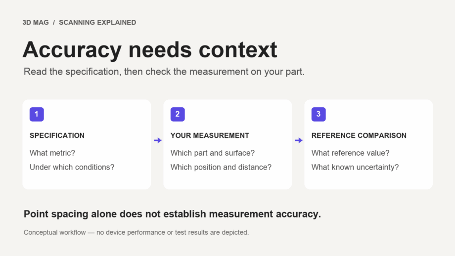
A scanner accuracy figure has to be read together with the metric, test procedure and conditions behind the specification. On its own, it does not tell you how the scanner will perform on your part. NIST researchers note that end users may not be able to make informed decisions when an instrument is specified under guideline test conditions but used for an application that deviates from them (NIST).
The same researchers also report that accuracy values of structured-light scanners vary with the location of the artifact and/or its distance from the scanner. As a result, a single accuracy value may not be adequate for the end user (NIST).
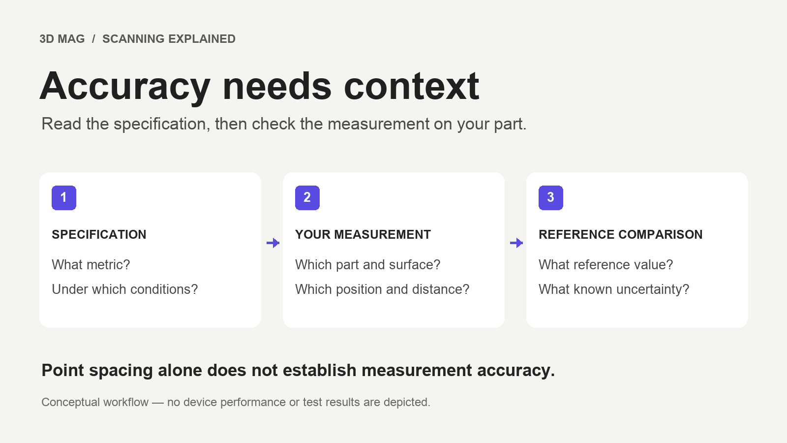
The practical answer has two steps. First, compare the conditions behind a datasheet number with your own job. Then check scan results on your own part against reference dimensions that have a known uncertainty.
Accuracy, precision, repeatability and resolution are different things
Datasheets and sales conversations often use these words interchangeably. The international metrology vocabulary (VIM) separates them.
The VIM defines measurement accuracy as the closeness of agreement between a measured quantity value and a true quantity value of a measurand. It also states that accuracy is not a quantity and is not given a numerical quantity value. A measurement is described as more accurate when its measurement error is smaller (BIPM). So when a datasheet quotes a number labelled “accuracy”, identify exactly which metric, test procedure and conditions it refers to.
| Term | VIM meaning | How it is expressed | Common misreading |
|---|---|---|---|
| Accuracy | Closeness of a measured value to a true value of the measurand (BIPM) | Not given a numerical value; identify the metric and conditions behind any quoted figure | Treating one figure as valid everywhere in the volume |
| Precision | Agreement between replicate measurements under specified conditions (BIPM) | Usually as dispersion, such as a standard deviation | Assuming consistent results must be correct results |
| Repeatability | Precision under a set of repeatability conditions (BIPM) | Dispersion under those stated conditions | Ignoring which conditions were held constant |
| Resolution | Smallest change in the measured quantity that causes a perceptible change in the indication (BIPM) | A smallest detectable change; can depend on noise | Reading point spacing or pixel count as accuracy |
Resolution deserves extra caution on scanner datasheets. NIST notes that some scanners offer a theoretical lateral resolution based on camera pixels and field of view, and that such a figure does not indicate the smallest feature the scanner can distinguish (NIST).
Uncertainty and metrological traceability
Measurement uncertainty is a non-negative parameter characterizing the dispersion of the values attributed to a measurand, based on the information used (BIPM). It is part of a specific measurement result, not a fixed property printed once for the scanner.
Metrological traceability relates a result to a reference through a documented unbroken chain of calibrations, each contributing to the measurement uncertainty. The VIM also notes its limits: traceability does not ensure that the uncertainty is adequate for a given purpose, or that there is an absence of mistakes (BIPM). Ask for documented calibration and traceability with a stated uncertainty, but do not treat that documentation by itself as proof that a scan is good enough for your tolerance.
Single-view versus multi-view evaluation: why one number is not enough
Some commercial structured-light scanners are evaluated with the German guidelines VDI/VDE 2634 Part 2 or Part 3. As NIST described them in 2019, Part 2 applies to scanners that produce area scans from a single view. Part 3 applies to scanners that use multiple views to extend the measurement volume. The editions NIST cites are Part 2 (2012) and Part 3 (2008) (NIST). Check the current editions before relying on them.
The distinction matters because an error measured within one view and an error measured across a multi-view, extended volume describe different situations. NIST also reports that accuracy values vary with artifact location and distance (NIST). When reading a specification, look for three things: which guideline or procedure was used, which units apply, and over what measuring volume the figure holds.
What moves the result: surface, environment, calibration and processing
The findings below come from NIST research on structured-light scanners. They are not manufacturer specifications, and they are not tests by this publication.
Surface: the VDI/VDE guidelines recommend diffusely scattering spheres and flat plates. NIST states that most optical scanners perform poorly with shiny and/or dark surfaces (NIST).
Lighting and temperature: NIST identifies ambient lighting as one of the major sources of error affecting data quality. It also notes that if an instrument is calibrated at one temperature and used to measure an object at a different temperature, the measurement may be erroneous (NIST).
Point density and position: in one NIST test, two similar spheres placed at two different distances from an unnamed commercial scanner were scanned 15 times. Scan data averaged 1465 points for one sphere and 13546 for the other, and the average radius errors were 1.1 µm and 0.3 µm respectively. NIST attributes the difference to varying point density and/or the sphere’s location in the work volume (NIST). This result describes one instrument under those conditions. It is not a benchmark for any product.
A workflow for verifying accuracy on your own part
The steps below are a proposed workflow. They are not a test that was carried out for this article.
- Define the measurand and the tolerance: which dimension, form or deviation actually matters for the part.
- Choose calibrated reference artifacts or reference dimensions with a stated uncertainty and a documented traceability chain.
- Match your real job: similar surface finish, size and position in the measuring volume, and the same scanning mode and settings.
- Control temperature and lighting, and record them, along with the scanner’s calibration state.
- Repeat the scans under the same conditions to estimate repeatability. Then vary position or operator if you need a broader picture.
- Compare the results with the reference values. Report the deviations together with their uncertainty, the conditions and the processing or filtering settings used.
Questions to ask before trusting a datasheet
- Which guideline or procedure produced the figure, and which edition?
- Was the figure measured in a single view or across multiple views?
- What units apply, and over what measuring volume or distance?
- Is a stated resolution measured, or theoretical (based on pixels and field of view)?
- What artifact surface was used, and how does it compare with your part?
- How many points were used, and how was the data filtered?
- What temperature and lighting conditions applied?
Sources
This explainer is based on the cited metrology vocabulary and published research; 3D Mag did not conduct hands-on testing. Publisher sponsorship.