
Summary
Wire arc additive manufacturing is a metal additive process in which wire is melted by an electric arc and deposited layer by layer to build a part. In current standards language, that places WAAM under directed energy deposition using wire and arc, and peer-reviewed literature explicitly categorizes WAAM as a DED process. [2] [12]
Its main advantage is deposition capability at scales suited to large parts and structural preforms. The trade-off is coarse bead geometry and demanding thermal control. Williams et al. report typical WAAM layer heights of about 1–2 mm and surface waviness of roughly 500 μm for single-track deposits, which is why the process is usually treated as near-net-shape and followed by machining. Heat accumulation, distortion, interpass conditions, inspection, and post-processing are part of the process plan rather than afterthoughts. [11] [9]
Terminology & Taxonomy: WAAM within Directed Energy Deposition
WAAM is not the same as the full DED category. DED is the broader additive-manufacturing family in which material is deposited and melted onto a target layer by layer, while WAAM identifies the wire-fed, arc-based branch of that family. The ISO/ASTM 52943-2:2024 abstract is explicit that its scope is DED using wire as feedstock and arc processes as the main energy source, and a peer-reviewed WAAM study likewise states that WAAM is categorized as a DED process. [2] [4] [12]
| Term | Plain meaning | Where used | Caution |
|---|---|---|---|
| DED | Material is deposited and melted onto a target | Standards, research, industry | Broad category |
| WAAM | Wire-fed, arc-based metal AM | Research, industry | Subset within DED |
| DED using wire and arc | Standard-friendly way to describe WAAM-type systems | Standards | More precise than shorthand |
| Arc DED / WA-DED | Informal or alternate shorthand | Industry, reports | Useful, but less formal than WAAM or “DED using wire and arc” |
| GMAW / MIG / MAG | Gas metal arc family | Welding and WAAM practice | MIG and MAG describe shielding-gas usage within GMAW |
| GTAW / TIG | Gas tungsten arc family | Welding and WAAM practice | Non-consumable tungsten electrode |
| PAW | Plasma arc welding family | Standards, welding references | Distinct from PTAW |
| PTAW | Plasma transferred arc welding | Hardfacing and coating contexts | Related term, not a synonym for PAW in WAAM |
NIST’s plain-language DED explainer describes the category as building material layer by layer by depositing and melting onto a target, which matches the hierarchy above even though NIST’s illustrated examples are laser-based. The wire-and-arc branch is then narrowed by the 52943-2 abstract and ASTM scope text, which list MIG/MAG/GMAW, TIG/GTAW, and PAW as the relevant arc families. [4] [2] [3]
In technical writing, “WAAM” or “DED using wire and arc” is usually the clearest choice when the process is specifically wire-fed and arc-based. “Arc DED” and “WA-DED” are understandable shorthand, but they are better treated as alternate wording than as the preferred formal taxonomy. [9] [12]
What WAAM Is — and What It Is Not
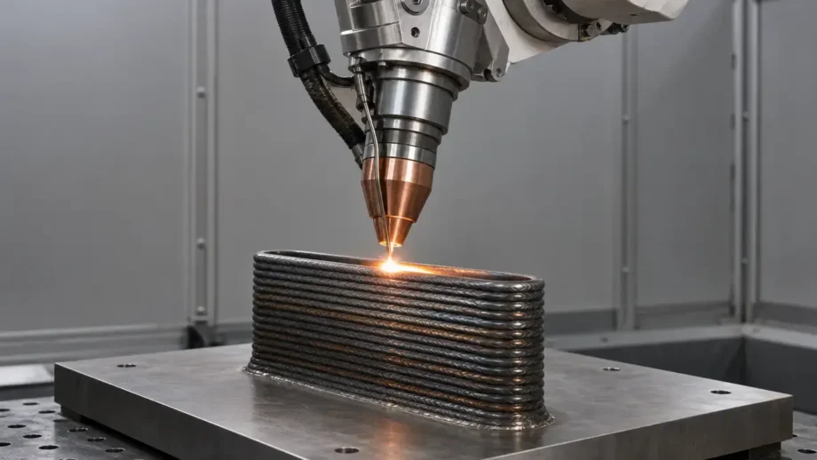
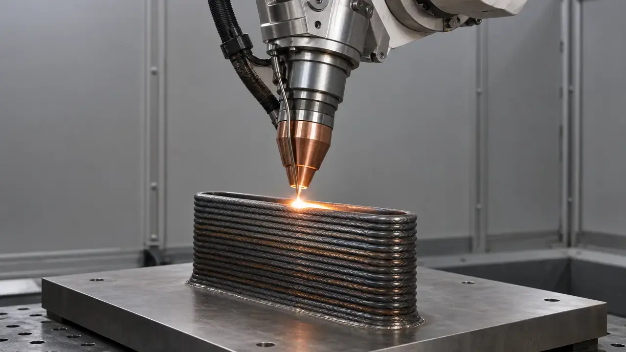
WAAM builds parts by feeding wire into an arc-generated melt pool under programmed motion control and stacking successive beads on a substrate or previously deposited layers. In practice, the output is usually a large weld-like preform or component with a corrugated as-built surface, not a finished surface straight off the machine. That is why the process is commonly described as near-net-shape and why machining is often built into the route to final geometry. Depending on alloy and shielding requirements, the setup may rely on local shielding or a more controlled environment, but the defining feature remains wire deposition driven by an electric arc. [11] [12]
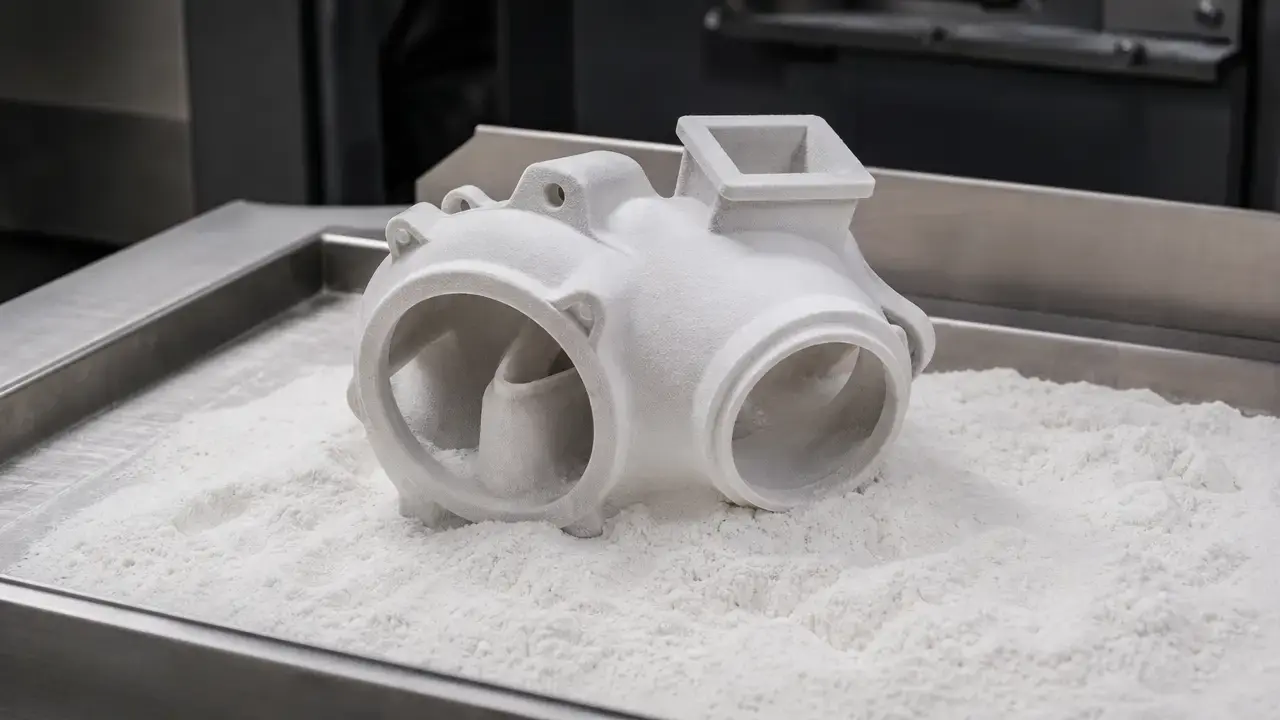
Just as important is what WAAM is not. It is not powder bed fusion, where powdered material is spread in layers, fused by a laser or electron beam, and the excess powder is removed after the build. It is also not a high-resolution process by default, and it is not a push-button route to qualified production parts. NIST’s recent qualification review highlights continuing gaps in monitoring and NDE specificity for metal AM process qualification, which is one reason WAAM still depends heavily on parameter control, inspection, and post-processing discipline. [5] [9]
Historical Background
WAAM should not be described as having been invented in 1925. A more accurate history is that an early patent often cited in the lineage was filed in 1925, while modern WAAM development for additive manufacturing was investigated much later, especially from the 1990s onward as welding-derived deposition concepts were adapted into more systematic additive processes. That later work is what turned the idea into a recognizable current manufacturing route, with controlled equipment, toolpath planning, process studies, and application-specific qualification work. [11]
How the WAAM Process Works
The wire arc additive manufacturing process begins with a substrate plate or previously deposited layer that provides the physical and thermal base for the next pass. Wire is fed into an electric arc, the wire tip and a local region of the substrate are melted, and a melt pool forms. As the torch or workpiece moves, that pool solidifies into a bead. Repeating the motion creates adjacent beads and stacked layers until the target shape is reached. Shielding gas is used where needed to protect the arc and molten metal from atmospheric contamination. Because the material is deposited as overlapping weld beads rather than spread into thin powder layers, the as-built surface is usually corrugated; that texture is a physical consequence of bead stacking, not automatically a defect. [11] [12]
Motion control matters as much as melting. Most WAAM systems use a robot or gantry to coordinate torch position, travel speed, and path order, and each new pass is deposited onto material that may still be hot from previous passes. As build height increases, thermal accumulation can change bead shape, remelting behavior, and distortion risk. That is why interpass cooling and monitoring are part of the build cycle itself, and why pauses can reduce apparent productivity even when deposition rate is high. Studies on power-controlled WAAM and broader NIST qualification work both point to heat accumulation as a central process-management problem rather than a secondary detail. [12] [9]
After deposition stops, the route is usually not finished. WAAM parts commonly proceed to inspection and machining, and many alloys also require post-processing heat treatment to reach the intended condition or reduce residual-stress-related risk. The qualification burden also continues past arc-off, because the evidence needed to release a part depends on the finished geometry, inspection results, and the process record that produced it. [11] [29] [9]
Basic WAAM process sequence
- Prepare the substrate plate and define the first deposition path.
- Feed wire into the arc and create a melt pool on the substrate.
- Deposit the first bead and allow it to solidify.
- Move the robot or gantry to the next path and stack adjacent beads.
- Repeat bead deposition to complete the layer and then build the next layer.
- Interpass cooling/monitoring (may include pauses).
- Continue until the target geometry is reached. [11] [12]
WAAM System Variants: GMAW, GTAW, PAW, and Controlled Transfer
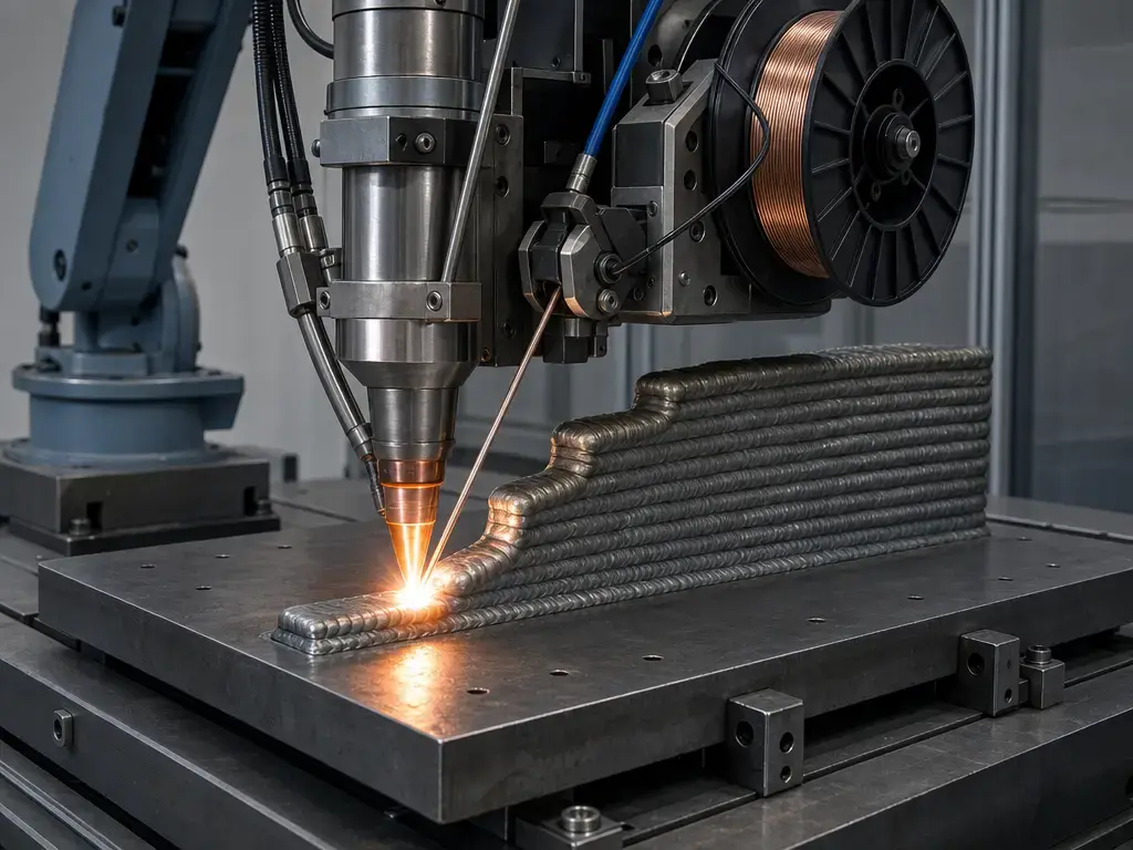
WAAM borrows established arc-welding process families because it uses the same basic physics: arc stability, filler transfer, shielding, and melt-pool control. In the ISO/ASTM 52943-2 abstract and ASTM scope text, the in-scope arc families for DED using wire and arc are MIG/MAG/GMAW, TIG/GTAW, and PAW. [2] [3]
| Variant | Electrode setup | Typical strengths | Cautions |
|---|---|---|---|
| GMAW | Consumable wire electrode and workpiece | High deposition capability, broad hardware base | Transfer mode and gas strongly affect bead shape and spatter |
| GTAW | Non-consumable tungsten electrode with separate wire feed | Stable arc and fine melt-pool control | Lower deposition capability than many GMAW setups |
| PAW | Non-consumable tungsten electrode with constricted plasma arc and separate wire feed | Concentrated arc and controllability | More complex torch and gas setup |
GMAW is the most familiar WAAM family because the wire itself acts as the consumable electrode. MIG and MAG are not different additive categories; they are gas-designation terms within the GMAW family, with inert versus active shielding affecting arc behavior and transfer. Controlled transfer modes often appear in this branch because they change droplet detachment, heat input behavior, and spatter. Cold Metal Transfer, or CMT, should therefore be treated as a controlled transfer or process-control variant used in some WAAM setups, not as a separate additive-manufacturing category. Manufacturer pages from MX3D and WAAM3D use that kind of wording when they list MIG, MAG, and CMT together. [16] [17]
GTAW and PAW differ from GMAW because they use a non-consumable tungsten electrode, with filler wire added separately. That configuration can give more direct control over the melt pool, though usually at lower deposition capability than high-productivity GMAW-based setups. ASM defines plasma arc welding as a gas-shielded arc welding process in which coalescence is achieved by heat from an arc created between a tungsten electrode and the workpiece. PTAW is related terminology, but it belongs mainly to powder-fed transferred-arc hardfacing contexts and should not be used as a synonym for PAW in WAAM discussions. [26] [27]
Key WAAM Process Parameters
WAAM process parameters are the control variables that shape thermal history, bead geometry, residual stress, distortion, defect risk, and the amount of stock left for finish machining. ABS guidance is useful here because it does not prescribe recipes, but it does spell out what needs to be defined in a DED procedure specification: heat input, scan pattern or toolpath, travel speed, hatch overlap, hatch spacing, feed rate, interpass temperature, and shielding-gas composition and flow rate, along with platform and environment details. That is the right level of thinking for WAAM: not “what amps should I use,” but “which variables must be specified, measured, and held under control for this alloy and geometry.” [7]
Parameters the article must define (no recipes)
- Heat input.
- Travel speed.
- Interpass temperature.
- Wire feed rate.
- Arc current and voltage.
- Shielding gas composition and flow rate.
- Hatch overlap and hatch spacing.
- Bead height and bead width.
- Cooling strategy.
- Toolpath strategy.
- Machining allowance. [7]
Thermal control
Heat input is the central thermal variable because it estimates how much energy is delivered per unit length of deposited track. Welding references commonly relate heat input to current, voltage, and travel speed, and they note the basic directional logic: increasing current or voltage tends to raise heat input, while increasing travel speed tends to lower it. But that figure is best treated as a comparative control variable, not a universal truth, because process efficiency assumptions and transfer mode matter. In WAAM, the practical importance is clear: too much heat can widen the bead, deepen remelting, increase distortion, and destabilize later layers. [25]
Interpass temperature controls the starting thermal state of the next layer, so it directly affects whether a wall stays stable as height builds. One low-alloy high-strength steel case study tested interpass temperatures of 150 °C, 350 °C, and 600 °C, found 350 °C to be an upper limit for that specific procedure, and reported deposit collapse at 600 °C. That does not create a universal rule, but it is a good illustration of why interpass limits must be alloy- and procedure-specific. Cooling strategy belongs in the same control family: pauses, active cooling, and path sequencing can all change residual stress and bead consistency. [28] [7]
Bead geometry and motion
Bead geometry is shaped by the interaction of feed rate, travel speed, arc stability, overlap, and path order. Faster travel speed generally reduces heat per unit length and tends to narrow the deposited track, while slower motion tends to widen the bead and increase remelting. Hatch overlap and hatch spacing determine whether adjacent passes fuse into a usable wall or leave valleys, peaks, and inconsistent side geometry. Toolpath strategy matters because each pass changes the thermal and geometric starting condition for the next one, which means a stable single bead does not automatically become a stable multi-bead wall. For that reason, engineers usually think in terms of a buildable wall plus a realistic machining allowance, not raw as-built appearance alone. [7] [13]
Capability & Metrics
In WAAM, deposition rate means the mass of material deposited per unit time, usually expressed in kg/h. Build rate is broader, because it depends on geometry and the actual volume completed over time, while productivity is broader still because it includes arc-off pauses, interpass cooling, setup, inspection, and machining before a usable part exists. That distinction matters. A peer-reviewed introduction describes WAAM deposition rates on the order of 2–4 kg/h, while Williams et al. report contextual examples including 0.8 kg/h for a Ti-6Al-4V spar and 3.5 kg/h for a wind-tunnel wing case. Those are reported cases, not universal averages. [12] [11]
Do not compare WAAM deposition rate to LPBF scan speed. Vendor numbers are examples, not averages. [11] [12] [16] [17]
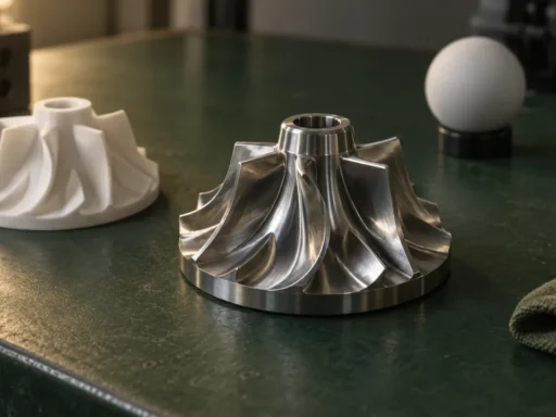
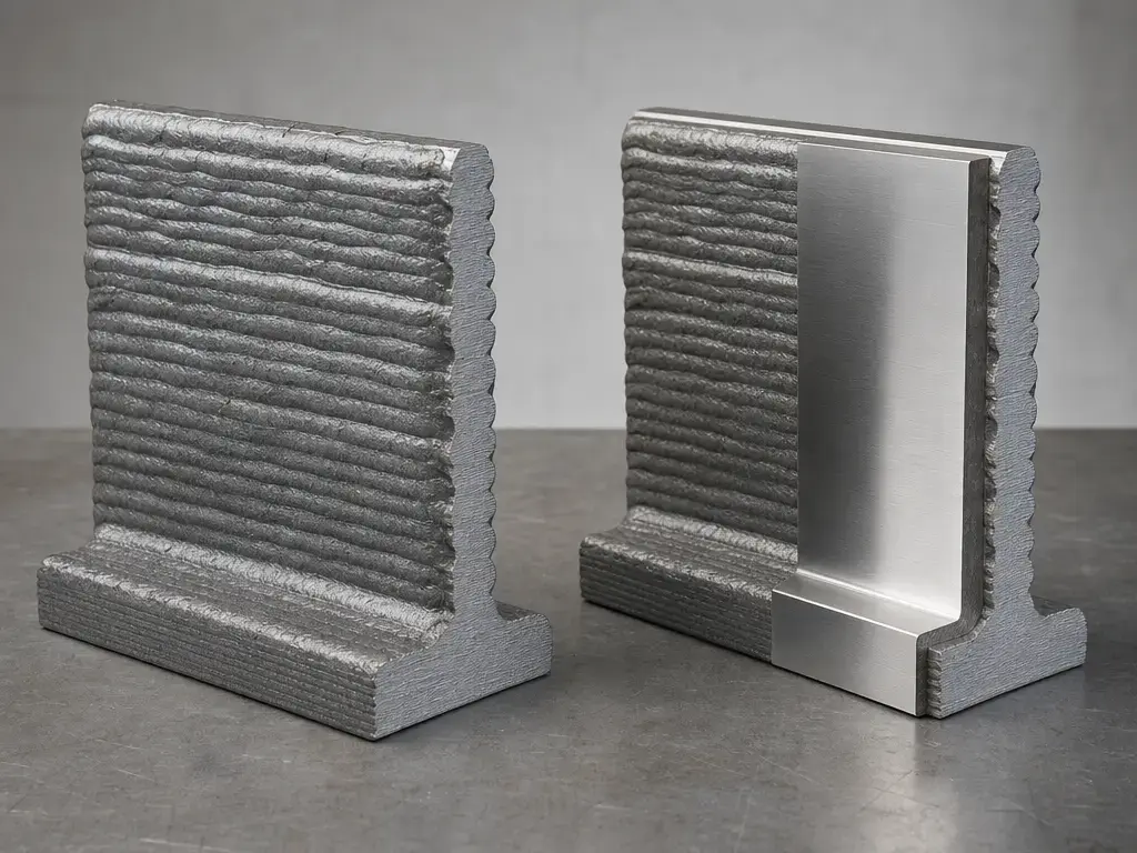
WAAM’s scale advantage is tied to relatively large beads. Williams et al. report typical layer heights of about 1–2 mm and waviness of roughly 500 μm for single-track deposits, which is why the process is usually framed as near-net-shape rather than net-shape. A 2021 review table makes the cross-process contrast clearer by listing typical SLM layer thicknesses at 10–100 μm and WAAM at 3000 μm in review context. Surface values still need careful reading, because different papers use different measurement methods and metrics. In one WAAM surface-measurement study, the reported mean surface roughness was 0.136 mm using that study’s own defined metric, and the optical system’s maximum absolute measurement error was under 0.15 mm. [11] [21] [15]
Dimensional capability should also be treated as case-based evidence, not as a single WAAM “accuracy band.” A 2024 robotic WAAM repeatability study reported average deviation from nominal ranging from 0.10 mm to 12.40 mm depending on the measured feature, while the standard deviation between prints ranged from 0.57 mm to 1.48 mm. The authors’ takeaway was effectively that the setup was repeatable, but not accurate enough in as-built form for final geometry without machining. That is a more useful way to read WAAM dimensional performance: can the process repeatedly leave a known, controllable allowance for post-machining, rather than can it match fine-feature powder-bed processes as built. [14] [10]
WAAM vs Powder Bed Fusion (LPBF) — Key Differences & When to Choose Which
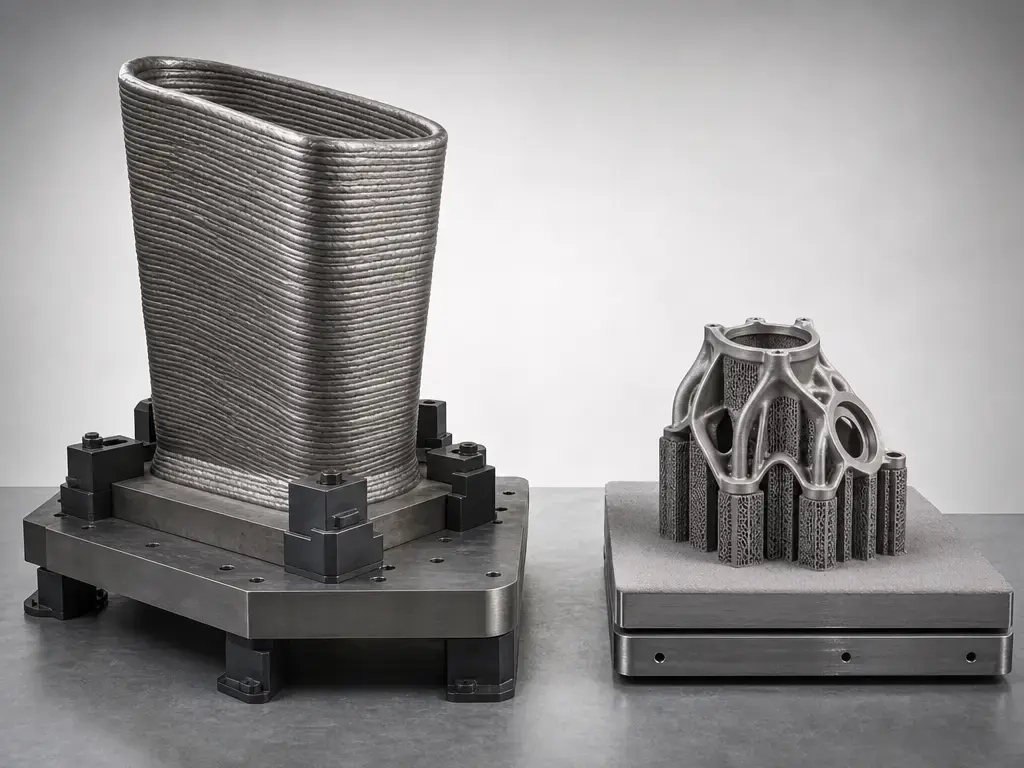
WAAM vs powder bed fusion is mainly a comparison of feedstock form, process architecture, and post-processing route. NIST describes DED as building material layer by layer by depositing and melting onto a target, while its PBF explainer describes melting and fusing layers of powder and then removing excess powder at the end of the build. In practice, WAAM usually operates as a wire-and-arc deposition process around a substrate and fixturing strategy, whereas LPBF typically operates in an enclosed powder-bed system. Support logic differs for the same reason. In LPBF, supports are often used for heat dissipation, mechanical constraint against warping, and structural support against sagging or dross formation, and later removal becomes part of the post-process burden. In WAAM, the substrate plate and fixturing usually do more of the holding work, and some robotic overhang strategies can be built without supports by changing deposition orientation instead of relying on dense removable support structures. [4] [5] [23] [24] [22]
| Factor | WAAM / wire-arc DED | Laser powder bed fusion (LPBF) | Article caveat |
|---|---|---|---|
| Feedstock | Wire | Powder | Cost and handling vary by alloy and facility |
| Energy source | Electric arc families such as GMAW, GTAW, or PAW | Laser | EB-PBF is separate from LPBF |
| Scale / envelope | Can be large-format on some systems with heavy fixturing or substrates | Usually constrained by enclosed build chamber | Tie machine size claims to named systems |
| Supports / fixturing | Often relies on substrate plate, path strategy, and fixtures | Supports often help with heat dissipation, warping control, and sag prevention | Support strategy is process-dependent |
| Post-processing | Machining is commonly used for final tolerances | Support removal and surface finishing are commonly required | Neither route is truly “no post” |
| Rate metrics | Deposition rate is usually discussed in kg/h | Build time depends on layers, scan strategy, and supports | Do not compare unlike metrics |
The comparison above combines official process descriptions, support-function literature, and machine-specific examples. For large-format WAAM, GEFERTEC’s arc80X is one manufacturer example that advertises component build volumes up to 8 m³. Representative LPBF examples are far smaller: EOS lists the M 290 at 250 × 250 × 325 mm with one 400 W laser, scan speed up to 7.0 m/s, and an approximately 100 μm focus diameter, while 3D Systems lists the DMP Flex 350 at 275 × 275 × 420 mm with adjustable layer thickness down to 5 μm and typical 30/60/90 μm layers. Those figures are machine-specific examples, not process-wide limits. Choose WAAM when part size, near-net preforms, and later machining make sense; choose LPBF when finer layers, smaller details, and powder-bed geometry control matter more. [18] [20] [19] [11] [9]
What Metals Can Be Used in WAAM?
The short answer to what metals can be used in WAAM is that steels, aluminum alloys, titanium alloys, and nickel-based alloys are the most common families reported in the literature. That still does not mean any metal that can be melted will be practical. Real selection limits include weldability, wire availability, oxidation sensitivity, shielding strategy, thermal behavior, and the qualification route required for the intended application. A material that works in a lab coupon may still be a poor choice for a large structural build if it feeds poorly, cracks, oxidizes, or accumulates damaging residual stress under the planned deposition strategy. [29]
Feedstock quality matters because the wire is part of the process-control chain, not just raw material. PAS 6010:2020 specifically addresses wire for DED and covers dimensions, tolerances, cast, and helix, along with other quality topics that affect stable feeding. Those details matter in WAAM because inconsistent wire delivery can show up as unstable transfer, variable bead shape, or interrupted builds. In practice, material selection is tied to a specific wire product, a specific shielding approach, and a specific qualification plan rather than just a generic alloy name. [6]
Applications of WAAM Metal Additive Manufacturing
WAAM metal additive manufacturing is most useful where large near-net-shape metal parts are needed and later machining is acceptable. The classic application pattern is structural preforms and large components rather than fine-feature parts. Williams et al. discuss examples such as a Ti-6Al-4V spar and wind-tunnel wing structures, which are useful illustrations of scale and buy-to-fly logic without implying that every WAAM program looks like aerospace. More broadly, the process is also relevant to tooling blanks, marine components, energy-sector hardware, and some repair- or cladding-adjacent workflows where deposition efficiency and material utilization matter more than fine surface finish. [11] [29]
The qualification burden changes with the application. A noncritical preform and a flight-relevant metallic part will not require the same evidence package, even if the same deposition hardware is used. ABS guidance helps define the parameter record that should exist, while NIST IR 8538 explains why monitoring and NDE evidence are still context-dependent in AM qualification. Lloyd’s Register has also issued guidance specifically for the certification of WAAM consumables, underscoring that feedstock control is part of application readiness. [7] [9] [8]
Limitations, Defects, and Quality Control
WAAM limitations are best understood as risks shaped by alloy, geometry, process settings, and thermal history rather than as inevitable failure modes. The literature repeatedly points to residual stress, distortion, porosity, lack of fusion, oxidation, bead instability, and anisotropy as possible concerns, but whether they occur and how severe they become depends on how the process is run. Large beads and cyclic reheating make that sensitivity stronger: a wall can be metallurgically sound in one region and still drift geometrically in another if heat accumulates unevenly or local support conditions change. The same coarse as-built surface that makes machining common can also complicate later inspection and NDE access. [11] [29] [9]
Monitoring and non-destructive evaluation are important, but the standards picture is still incomplete. NIST IR 8538 frames this as a knowledge-gap problem: limited specificity in standards can hinder the use of monitoring and NDE data for process qualification, even when sensing data exist. That is why WAAM parts should not be treated as “born qualified.” The qualification route still depends on what evidence is needed for that alloy, geometry, machine, and service case, and on how confidently the chosen inspection methods can detect the relevant flaws. [9]
The practical baseline is disciplined documentation. NIST’s AM test artifact guidance states that all pertinent process parameters and machine settings should be documented, and it identifies geometric accuracy and surface roughness as primary characterization targets. ABS then provides a practical checklist of the process variables that should be defined and controlled. That combination is a good minimum standard for comparing builds, diagnosing drift, and showing whether a result came from the intended process or from uncontrolled variation. [10] [7]
Standards & Guidance Map
For WAAM, the standards landscape is better understood as a map than as a single rulebook. ISO/ASTM 52900:2021 is the vocabulary anchor for additive manufacturing and remains the current edition confirmed in 2025. ISO/ASTM 52943-2:2024 provides aerospace-focused requirements for metallic parts produced by directed energy deposition using wire and arc, and ASTM’s scope page gives an accessible cross-check of the in-scope arc families. PAS 6010 addresses wire-feedstock quality for DED, while ABS and Lloyd’s Register provide practical guidance on process control and WAAM consumables. [1] [2] [3] [6] [7] [8]
What these documents do not provide is a universal parameter recipe. They standardize terminology, define control topics, and help structure evidence, but they do not eliminate the need for testing and qualification work. NIST IR 8538 is especially useful here because it makes clear that monitoring, NDE, and qualification practice still have specificity gaps in real use. [9]
Current Research & Market Context
Current WAAM research is heavily focused on turning parameter setting into a more measurable and less trial-and-error activity. A 2026 gradient-based study reported a 66% reduction in experimental effort while keeping bead-height and bead-width differences below 5% relative to a conventional approach. It also emphasized a point that matters beyond that one paper: set parameters and actual parameters can differ during production, especially for variables such as wire feed speed. That line of work matters because WAAM behavior is governed by what the process actually delivers at the arc and melt pool, not only by what the machine was told to do. [13]
Market claims need a different reading standard than journal results. MX3D, for example, presents deposition-rate claims of 2–8 kg/h and elsewhere 2–15 kg/h depending on material, process, and geometry, while WAAM3D promotes deposition rates up to 15 kg/h and lists MIG, MAG, and CMT support on a named hardware page. Those are manufacturer claims or system-specific examples, not category-wide averages. They are still useful as indicators of where commercial WAAM development is focused: higher throughput, better control of transfer behavior, and more integrated monitoring around large-format metal builds. [16] [17]
Where Wire Arc Additive Manufacturing Fits in Metal AM Today
Wire arc additive manufacturing fits best in the part of metal AM where large size, good material utilization, and near-net-shape economics matter more than fine-feature resolution. DED is fundamentally a deposition-first process, and WAAM inherits both the strengths and the constraints of that identity: large beads, accessible deposition hardware, thermal-management challenges, and a frequent need for machining after the build. That makes it a strong candidate for big preforms and structural parts, but a weak substitute for every powder-bed use case. [4] [11]
Choose WAAM when the part is large, the alloy and wire route are practical, and machining is acceptable. Choose LPBF when thinner layers, finer detail, and powder-bed build logic better match the design requirement. Neither process is universally better; they solve different production problems and impose different post-processing and qualification burdens. [5] [11] [9]
FAQ
What is wire arc additive manufacturing?
WAAM is a metal additive process that feeds wire into an electric arc and builds geometry layer by layer by depositing successive beads onto a substrate or prior layer. In standards language, it sits within directed energy deposition using wire and arc, and peer-reviewed literature explicitly categorizes WAAM as a DED process. [2] [12]
Is WAAM the same as DED?
No. DED is the broader process family, while WAAM is the wire-fed, arc-based subset within that family. If the feedstock or energy source changes, the process may still be DED but no longer WAAM. [2] [4] [12]
How does WAAM work in plain technical terms?
Wire is fed into an arc, a melt pool forms on a substrate or previous layer, and motion control places beads one after another until a 3D shape is built. Because those beads are relatively large, the as-built surface is usually corrugated and later machining is common. [11] [12]
What are the key WAAM process parameters?
The most important documented variables are heat input, travel speed, feed rate, overlap or spacing, interpass temperature, shielding-gas composition and flow rate, and toolpath strategy. Practice is less about universal recipes than about how those variables control thermal history and bead geometry. One published steel case found a 350 °C upper interpass limit for that procedure and collapse at 600 °C, which is a reminder that limits are alloy- and procedure-specific. [7] [28] [25]
What metals can be used in WAAM?
Common WAAM material classes include steels, aluminum alloys, titanium alloys, and nickel-based alloys. In practice, suitability depends on more than alloy family: weldability, wire availability, oxidation control, feed stability, and the qualification route all matter. PAS 6010 also highlights wire-specific quality topics such as dimensions, tolerances, cast, and helix. [29] [6]
WAAM vs powder bed fusion: what are the biggest practical differences?
WAAM uses wire and an electric arc, usually around a substrate and fixturing strategy, while LPBF fuses powder in an enclosed chamber. LPBF supports often serve thermal, mechanical, and structural roles and then need removal, whereas WAAM more often relies on the substrate, fixtures, and path strategy. That is why WAAM is often chosen for larger near-net-shape preforms and LPBF for finer geometry. [5] [23] [24] [22]
How are WAAM parts qualified and inspected in practice?
Qualification is still context-dependent. Standards and guidance can tell you what to document and what categories of evidence matter, but NIST notes that monitoring and NDE standards are not fully specific for every process-qualification use case. In practice, the route depends on the application, the alloy, the machine, the inspection method, and the completeness of the process record, including wire quality and parameter control. [2] [7] [9] [8]
Sources
Manufacturer claims and machine-specific specifications are labeled as such in the article.
- ISO/ASTM 52900:2021 Additive manufacturing — General principles — Fundamentals and vocabulary
- ISO/ASTM 52943-2:2024 Additive manufacturing for aerospace — Process characteristics and performance — Part 2: Directed energy deposition using wire and arc
- ASTM F3594-24 store scope page
- Directed Energy Deposition | NIST
- Powder Bed Fusion | NIST
- PAS 6010:2020 Additive Manufacturing. Wire for directed energy deposition (DED) processes in additive manufacturing. Specification
- ABS Requirements for Additive Manufacturing (July 2022)
- LR-GN-011 Guidance Notes for the Certification of Consumables for WAAM
- NIST IR 8538: In-process monitoring and non-destructive evaluation for metal additive manufacturing processes
- NIST Additive Manufacturing Test Artifact
- Williams et al., “Wire + Arc Additive Manufacturing”
- Israr, Buhl, and Bambach, “A study on power-controlled wire-arc additive manufacturing using a data-driven surrogate model”
- “Process parameter determination in wire arc additive manufacturing using parameter gradients and multi-sensor data fusion”
- “Geometric Repeatability Study for Robotic WAAM” (Solid Freeform Fabrication 2024)
- “Determination of Surface Roughness in Wire and Arc Additive Manufacturing Based on Laser Vision Sensing”
- MX3D, “The WAAM Guide”
- WAAM3D hardware page
- GEFERTEC ARC series
- 3D Systems DMP Flex 350
- EOS M 290 system data sheet
- Materials review PDF with cross-process layer-thickness table
- SINTEF: “Wire-arc additive manufacturing of structures with overhang: Experimental results depositing material onto fixed substrate”
- “Advancements and challenges in overhang structure fabrication during laser powder bed fusion: a comprehensive review”
- “Support structure removal in laser powder bed fusion of metals”
- AISC Bridge Welding Reference Manual
- ASM Handbook: “Plasma Arc Welding”
- AWS Welding Digest: “Why Choose PTAW?”
- DOAJ record for the 2022 interpass-temperature case study
- “Current Status and Perspectives on Wire and Arc Additive Manufacturing (WAAM)”