
Summary
Choosing a 3D scanner for bicycle work starts with the output, not with a single headline number. If you searched for “3D scanner for bicycle,” you probably mean one of several different jobs: a whole-frame reference mesh, a detailed local reverse-engineering scan, an inspection-oriented workflow, or a lower-stakes visual capture. Consumer or reference scanning is not the same as metrology or inspection. [1] [6] [11]
| Task/output | Best-fit scanner class | Why it fits | Main limitation/risk |
|---|---|---|---|
| Whole-frame reference mesh | Larger-FOV handheld structured light | Faster coverage on long geometry and better shape context | Drift and occlusion on tubes and junctions can still undermine long-range coherence. [8] [13] |
| Local details and junctions | High-resolution handheld structured light | Better fit for tube junctions, dropouts, cable ports, and other small features | Short working distance and heavier stitching burden on a full frame. [6] [7] |
| Inspection / QA | Metrology-grade handheld blue-laser | Better suited to traceability-aware workflows and documented performance | Higher process-control burden; scanner class alone does not make the workflow metrology. [11] [1] |
| Visual capture only | Consumer/reference scanner | Sufficient for appearance, packaging checks, or rough planning | Not suitable for safety-critical conclusions about frame alignment, repair validation, or QA. [1] [11] |
Local accuracy, registration drift, and distance-dependent or volumetric performance are different things. A scanner can resolve a tube junction well and still accumulate error across an entire frame length. Published examples such as Artec Spider II’s “up to 0.05 mm + 0.3 mm/m” and Creaform HandySCAN BLACK|Elite’s “0.020 mm + 0.040 mm/m” are useful because they show that long-object behavior is not the same as small-area behavior. ISO 10360-13 concerns acceptance and reverification of performance when measuring lengths as stated by the manufacturer, under defined conditions, not a guarantee that any glossy or dark bike in your shop will behave like the brochure test artifact. [6] [11] [1]
Decide the job first: whole frame vs local features vs inspection
The first decision is not which device to buy, but what the scan must produce. A visual reference, packaging-fit check, CFD-oriented exterior reference, and CAD reverse-engineering project do not ask the same thing from the data. A whole-frame mesh mainly needs coverage and coherent overall shape. A local-feature job needs dense detail around tube junctions, dropouts, the bottom bracket shell, the fork crown, or small bosses and ports. Inspection and QA go further: they require repeatable setup, traceability-aware methods, and a clear statement of what the numbers mean. Those outputs overlap, but they are not interchangeable. [6] [11] [14] [15]
The boundary is simple: whole-frame accuracy is not the same as the scanner’s headline local accuracy number. A scanner can perform well on a small feature and still drift across a full bicycle if registration is weak, the geometry is repetitive, or the part is re-fixtured without a stable reference. This is also where repeatability and uncertainty matter. Repeatability is about getting the same result again under the same method; uncertainty is about how much confidence you can defend in the measurement result. For alignment checks, repair validation, or QA, consumer or reference scanning is not enough on its own; you need a validated metrology workflow, a controlled setup, and independent verification. [6] [11] [1]
Why bicycle frames are hard to 3D scan
Bicycle frames combine several traits that are awkward for optical 3D capture. They are long, thin, and full of partial views rather than broad, obvious surfaces. The software often sees one section of tubing at a time, not one compact object silhouette. Bikes also repeat similar forms: round or near-round tubes, mirrored stays, and junctions that can resemble one another from different angles. That makes registration more fragile than on a compact casting or housing. If the software keeps matching one plain tube section to another, drift can accumulate even while the mesh still looks visually plausible. [8] [13]
Surface condition adds another layer of difficulty. NIST notes that most optical scanners perform poorly with shiny and/or dark surfaces, and Artec’s documentation lists black or very dark surfaces, shiny or reflective objects, and thin edges as hard-to-scan cases. Artec also notes that some HD-capable workflows can handle dark or shiny surfaces better, but the general warning still applies: bicycle finishes are rarely as cooperative as a lab artifact. [8] [13]
Common bicycle scanning problem areas:
- head tube / top tube / down tube junction — occlusion and alignment ambiguity where multiple tube lines overlap. [8] [13]
- bottom bracket shell and underside — hidden surfaces and awkward sight lines that break pass continuity. [8] [13]
- dropouts and derailleur hanger zone — thin edges and small features that are easy to lose in cleanup. [8] [13]
- fork crown and inside fork blades — occlusion and poor access from the scanner’s field of view. [8] [13]
- brake mounts, bottle bosses, and cable ports — local detail on small features, often near edges. [8] [13]
- glossy carbon, polished metal, matte-black finishes, and protective films — reflectivity or low-signal surfaces that can destabilize capture. [8] [13]
For that reason, bike frame 3D scanning is usually less about one perfect pass and more about overlap, stable reference, and keeping enough unique geometry visible for reliable alignment. If the setup forces the software to infer too much from repeated tubes or hidden areas, the model may look complete while still being weak as a measurement basis. Long-frame workflows often benefit from targets, reference geometry, or surroundings that help anchor the registration chain. [8] [19]
Technology options and what photogrammetry is doing in a bike workflow
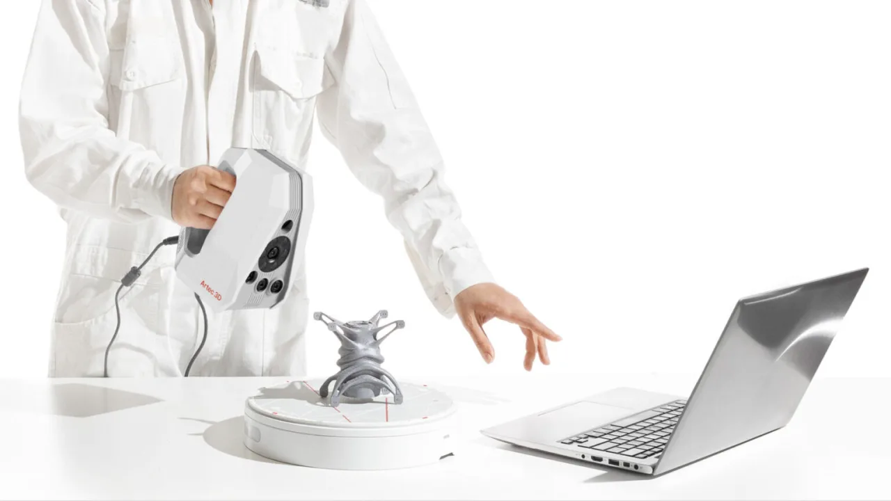
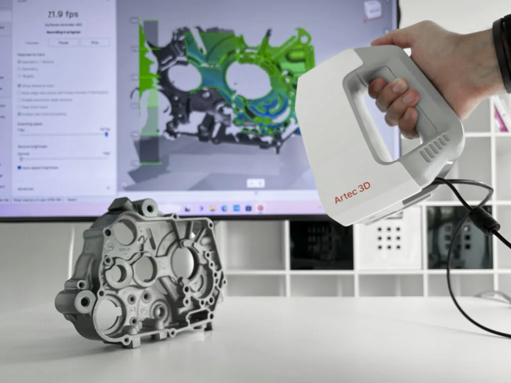
Handheld structured-light scanners are often the first place people look for local bike detail. They fit well when the task is a dropout, cable port, tube junction, fork crown feature, or other small external geometry that needs good surface detail and quick operator feedback. Their strengths are close-range work and detail capture. Their limits matter just as much: short working distances, smaller fields of view, and a higher stitching burden on long, repetitive frames. A structured-light handheld can be an excellent local-detail tool without being the best single-tool answer for full-frame capture. [6] [7] [8]
Metrology-grade handheld blue-laser scanners sit in a different part of the decision space. They are usually chosen when repeatability, documented performance, and auditability matter more than convenience. Creaform’s HandySCAN BLACK|Elite, for example, is presented with 0.025 mm accuracy, volumetric accuracy of 0.020 mm + 0.040 mm/m, a recommended part size range of 0.05–4 m, acceptance testing based on VDI/VDE 2634 part 3, and performance tests done in ISO/IEC 17025 accredited calibration laboratories. Those details do not certify your frame automatically, but they show why this class is better aligned with inspection-oriented workflows. [11]
Photogrammetry can play two roles in bicycle work. One is lower-cost standalone reference capture, where the goal is mainly visual or contextual geometry rather than a traceable inspection result. The other is as a support layer for long, repetitive objects: targets on the frame, stand, or nearby fixtures can help create a reference frame that stabilizes alignment as you move around the bike. Creaform’s bike workflow example explicitly places positioning targets on the object and in its surroundings for this reason. By contrast, tripod time-of-flight LiDAR belongs to a different range class altogether: ASTM E2938 defines medium range as at least part of 2 to 150 m, which is useful for context capture but not the normal starting point for tube-junction bicycle scanning. [19] [4]
Performance metrics that matter
The most common buying mistake is reading one spec as if it explained the whole job. Accuracy, resolution, repeatability, and accuracy over distance do not mean the same thing. Accuracy is about closeness to the reference value under defined conditions. Resolution is about how finely the system can represent detail, which is not the same as truth. Repeatability is about consistency when you repeat the method. On bikes, all three matter, because a scanner can show crisp texture and convincing detail while still drifting over the full frame length. NIST’s structured-light review explicitly warns that a single accuracy value may not be adequate for the end user, because performance varies with artifact location and distance from the scanner. [13] [6] [7] [11]
That is where distance-dependent or volumetric performance becomes more useful than a simple local headline. Artec Spider II lists accuracy up to 0.05 mm, resolution up to 0.05 mm, and 3D accuracy over distance up to 0.05 mm + 0.3 mm/m. HandySCAN BLACK|Elite lists 0.025 mm accuracy and volumetric accuracy of 0.020 mm + 0.040 mm/m. These formulas are not predictions for a specific bicycle frame, but they show why object length matters. A small dropout and a full frame are not the same metrology problem, even when scanned by the same device. [6] [11]
Working distance, field of view, and data rate also affect the real job. Spider II lists a working distance of 0.19–0.3 m and a field of view of 128 × 104 mm at the closest range to 171 × 152 mm at the furthest range. That is useful for dense local work, but it also means more passes on a long frame than a larger-FOV system would require. Space Spider similarly targets detailed work, with up to 0.05 mm accuracy, up to 0.1 mm resolution, object size starting from 5 mm, up to 7.5 FPS, and up to 1 mln points/s. [6] [7]
Speed specs should also be read carefully. Spider II lists up to 30 fps real-time fusion and up to 8 mln points/s, while Space Spider lists up to 7.5 FPS and up to 1 mln points/s. Those are capture-rate figures, not total project times. Real clock time is often dominated by cleaning, fixturing, overlap management, rescan passes, registration review, and mesh cleanup. Artec’s reverse-engineering overview says Vorteq captured each bike in under one minute, but that is a case-study anecdote tied to a specific workflow, not a general benchmark for bike frame scanning. [6] [7] [9]
Standards and traceability caveat
ISO 10360-13:2021, Edition 1, is a 52-page standard whose abstract states that it specifies acceptance tests for verifying the performance of an optical 3D coordinate measuring system when measuring lengths as stated by the manufacturer, and reverification tests for periodic rechecking by the user. It also states that applicability depends on object surface characteristics being restricted and within a cooperative range. That matters because real bicycle finishes often are not cooperative. [1]
VDI/VDE 2634 Blatt 3 is the older multi-view area-scanning reference that many brochures and comparison discussions still cite. The DIN Media listing identifies it as “Optical 3D-measuring systems – Multiple view systems based on area scanning,” dated 2008-12, 20 pages. As accessed on July 28, 2026, that DIN listing is also marked withdrawn and recommends application of DIN EN ISO 10360-13:2023-11. In other words, VDI/VDE 2634 Part 3 still matters as context for older vendor claims, but it should not be treated as the last word on what your bike scan means. [2] [11]
Why published specs aren’t directly comparable: different brochures and standards contexts can use different artifacts, different environmental conditions, different acceptance language, and different assumptions about cooperative surfaces. Real bikes are long, repetitive, partly hidden, and often shiny or dark. That is why vendor figures should be read as conditional performance statements, not universal predictions for a specific frame in a specific shop. [1] [2] [13]
Scanner classes for bicycle scanning
The table below is best read as a job-to-tool map, not as a ranking. A device can be highly appropriate for one bicycle task and awkward for another. The right class depends on object scale, surface behavior, and whether traceability or uncertainty statements matter. A detail-focused scanner can be excellent for dropouts and tube junctions while still being a poor choice for a single-pass full-frame workflow. [6] [7] [11]
| Scanner class | Best bicycle use | Main risk | Evidence note |
|---|---|---|---|
| High-resolution handheld structured light | Tube junctions, dropouts, cable ports, small brackets | Narrow coverage and more stitching work on a full frame | Artec Space Spider is detail-oriented, with up to 0.05 mm accuracy, up to 0.1 mm resolution, starting object size of 5 mm, up to 7.5 FPS, and up to 1 mln points/s. [7] |
| Metrology-grade handheld blue-laser | Inspection-oriented capture, QA, and longer-object measurement workflows | Higher setup burden and less tolerance for process shortcuts | HandySCAN BLACK|Elite is presented with 0.025 mm accuracy, 0.020 mm + 0.040 mm/m volumetric accuracy, 0.05–4 m recommended part size, and ISO/IEC 17025 lab framing. [11] |
| Larger-FOV handheld structured light | Whole-frame reference mesh and faster pass coverage | Long-range drift if overlap is weak or geometry is repetitive | The class advantage is coverage, but overlap and common reference still govern success on bike frames. [8] [13] |
| Photogrammetry-assisted workflow | Scale or alignment support on long, repetitive frames | Lower confidence if used alone for inspection claims | Targets on the object or nearby surroundings can create a reference frame that improves tracking logic. [19] |
| Tripod ToF LiDAR / medium-range | Context capture or environmental reference, not fine frame detail | Too coarse and too distant for most junction-level bike work | ASTM E2938’s “medium range” scope covers systems operating within at least part of 2 to 150 m. [4] |
| CT | Internal inspection where the goal is hidden structure, not exterior surface CAD | Outside the normal scope of bicycle surface scanning | Included here only to separate internal inspection from external frame capture. |
A practical reading of the table is straightforward. If the job is a local junction, favor detail and close control. If the job is a whole-frame reference mesh, favor coverage and a workflow that preserves alignment. If the job is inspection or QA, ask first whether you need traceability, repeatability, and an uncertainty-aware measurement basis, because that changes both the scanner class and the operating method. If the job is hidden structure, you are outside the normal surface-scanning tree. [1] [11] [13]
A narrow budget example shows why price alone is a weak shortcut. Creaform’s HandySCAN 3D PRO Series page listed a US$25,740 bundle as accessed on July 28, 2026, but the page also states that this RRP excludes taxes, shipping, import fees, laptop, training, and additional options. That makes it a dated context point, not a reliable market average. [20]
Artec Space Spider vs Artec Spider II
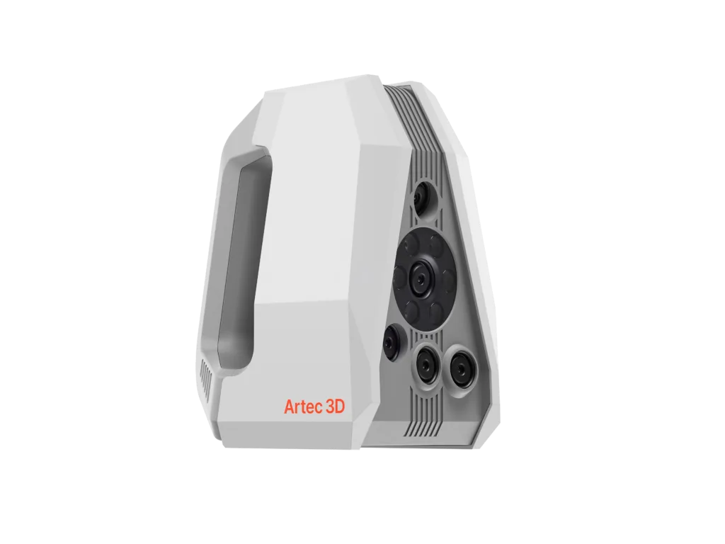
Both Artec Space Spider and Artec Spider II belong in the detail-focused part of bicycle scanning. They are best framed as tools for tube junctions, dropouts, fork-crown details, cable ports, small brackets, and partial-frame reverse engineering rather than as guaranteed one-tool solutions for whole-frame inspection. Space Spider lists up to 0.05 mm accuracy, up to 0.1 mm resolution, object size starting from 5 mm, and up to 7.5 FPS. Spider II lists up to 0.05 mm accuracy, up to 0.05 mm resolution, and accuracy over distance up to 0.05 mm + 0.3 mm/m. [7] [6]
-
When Space Spider makes sense:
-
You are scanning smaller local zones such as a dropout, boss, or BB-adjacent feature. [7]
-
You want detail capture without turning the workflow into a whole-frame coverage project. [7]
-
You can accept more stitching work in exchange for close-range detail. [7]
-
You are working on a part or sub-area that can be isolated from the rest of the frame. [7]
-
When Spider II makes sense:
-
You want the same headline local accuracy class with finer listed resolution and explicit accuracy-over-distance framing. [6]
-
You are planning around a working distance of 0.19–0.3 m and a field of view of 128 × 104 mm to 171 × 152 mm. [6]
-
You want higher listed capture throughput, with up to 30 fps and up to 8 mln points/s. [6]
-
You also care about hardware and workflow details such as 0.95 kg weight, Thunderbolt 4 host compatibility, Windows 10 x64 / 11 support, and CAD output formats including STEP, IGES, and X_T. [6]
Neither scanner should be presented as a universal answer for every bicycle task. On a full frame, the limiting factor is usually overlap, stable reference, and registration discipline, not just nominal local accuracy. A dense local-detail handheld can produce excellent tube-junction data while still leaving the long-range frame relationship underdefined. [8] [6] [7]
How to do bike frame 3D scanning
The capture workflow should begin with the output you need. Decide whether the result is a visual reference, print reference, CFD-style exterior mesh, CAD reverse-engineering input, or inspection record before you touch the scanner. Then remove anything that moves, clean the frame, and decide how you will preserve reference. In most cases, moving around a static frame is safer than repeatedly moving the frame itself, because every flip or re-fixturing step risks breaking the registration chain. Sometimes flipping or rotating the frame improves access to the underside of the bottom bracket shell or the inside of the fork crown, but if your common geometry disappears, you may gain access at the cost of coherence. That tradeoff matters more on a bike than on a compact part. [8] [19]
Artec Studio’s scanning guidance is directly relevant here: if you are capturing an object over several scans, each scan should retain a common area for alignment, and if you are capturing it in one scan, the pass should go all the way around the object plus a little more than 360 degrees. On a bicycle, those rules matter because repetitive tubes can make the software overconfident. Targets or nearby reference geometry can help when the frame itself does not offer enough unique surfaces. Creaform’s bike example uses positioning targets on the bike and on a nearby cardboard box specifically to create a reference frame for the scanner. [8] [19]
Workflow checklist:
- Define the output: visual reference, print reference, CFD-style exterior mesh, CAD, or inspection. [1] [11]
- Remove moving parts and accessories that would blur or shift geometry. [8]
- Clean dirt, wax, and loose contamination from the frame. [8]
- Choose the fixturing strategy: move around a static frame when possible, and only rotate or flip the frame if you can preserve continuity. [8] [19]
- Keep a stable external reference if you expect to reposition the frame. [19]
- Add targets or reference geometry when the frame alone will not anchor registration reliably. [19]
- Plan pass coverage around tube junctions, the BB area, dropouts, and the fork crown. [8]
- Check overlap on site, especially anywhere geometry is hidden or repetitive. [8]
- Use spray only where justified, and remember that the coating changes the surface. [8] [16] [17] [18]
- Review holes, drift, and registration strength before leaving the capture setup. [8]
Surface preparation should be selective, not automatic. Artec’s documentation says black or very dark surfaces, shiny or reflective objects, and thin edges are hard-to-scan cases; its suggested fixes include anti-glare spray, scanner tilt on reflective objects, and added background geometry for thin edges. AESUB Blue lists a coating thickness of 8–15 μm, a scanning time of about 1–2 hours, and sublimation time of about 4 hours. The scientific literature also warns that coating performance depends on operator skill and the number of passes, and that coatings can be in the order of tens of micrometers. Spray is useful, but it is not dimensionally neutral. [8] [16] [17] [18]
From point cloud or mesh to CAD: what CAD-ready actually means
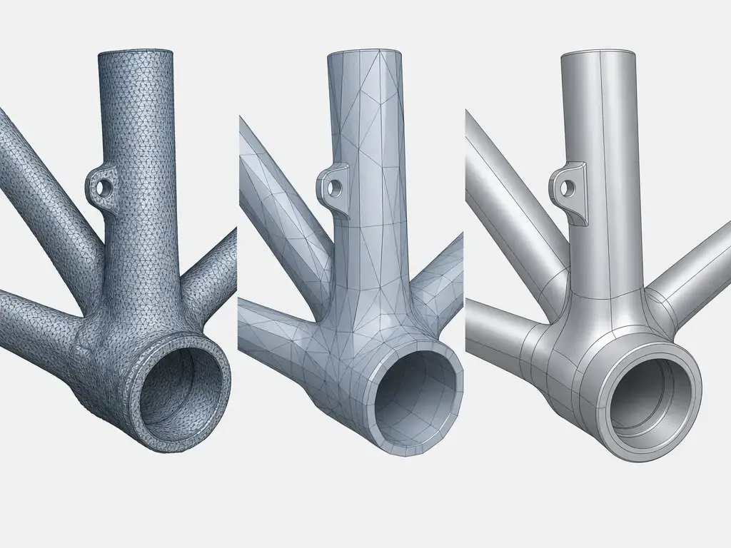
“CAD-ready” is one of the loosest phrases in scanner marketing, so it helps to split it into three levels. Level 1: reference mesh in CAD. At this level, the scan is imported mainly as context for comparison, tracing, or packaging checks. Autodesk Fusion’s Insert Mesh documentation supports STL, OBJ, and 3MF for this stage. That is useful, but a mesh in CAD is still a mesh; it is not automatically editable design intent. [14]
Level 2: mesh-to-BRep conversion. Fusion defines Faceted conversion as turning individual mesh faces into individual faces on the new solid or surface body, while Prismatic conversion merges groups of faces in prismatic features into singular faces, using face groups to infer prismatic features. That can help create a technically solid body, but it does not recover the engineering logic of a bicycle frame. On tube blends, lug transitions, and irregular junctions, the result may be solid geometry that is still awkward to edit or dimension meaningfully. Some scanners and software pipelines also advertise CAD export paths such as STEP, IGES, and X_T, but export availability is not the same thing as an editable, well-structured model. [15] [6]
Level 3: rebuilt editable engineering geometry. This is where the scan becomes a source for centerlines, axes, reference planes, symmetry decisions, and manufacturable intent. Tubular bikes often need this level because a clean engineering model is rarely identical to the raw mesh. A good rebuild is validated against the scan, not merely converted from it. [15] [14]
Applications and when to outsource
A bicycle 3D scan can support accessory fitting, legacy-part documentation, jigs and mounts, one-off design adaptation, and CFD reference geometry. It can also help preserve a frame’s external shape for later comparison. In Artec’s Vorteq case study, the company says it used an Artec Space Spider to capture the bike’s frame and generate deviation plots showing where frames were flexing. That is a useful example of a scan-to-analysis path, but it is still a case study, not a template for every bike job. [10]
Outsource when the result will be used for safety-critical alignment conclusions, repair validation, or QA evidence. That is where the earlier boundary matters again: consumer or reference scanning is not enough on its own. If the real question is “is this frame in tolerance, and can I defend that claim,” ask for a metrology-capable service with a documented test basis, a controlled setup, and independent verification. A HandySCAN BLACK|Elite-style workflow is relevant here because it is framed with volumetric performance, a standards-based acceptance-test reference, and ISO/IEC 17025 calibration-lab context, which is a different level of evidence from ordinary reference capture. [11] [1]
Limitations and failure modes
The first thing that often breaks on a bicycle scan is not the scanner, but the registration chain. Drift grows when the frame is long and repetitive, and symmetry can cause the software to confuse one tube section with another. Occlusion hides the underside of the bottom bracket shell, the inside of the fork crown, or the back side of a dropout. NIST notes that most optical scanners perform poorly with shiny and/or dark surfaces, and Artec’s documentation adds that thin edges may need background geometry to capture reliably. [13] [8]
Handling can make a good capture bad. If the frame flexes, moves, or is re-fixtured without a stable reference, the mesh may still look clean while the geometry is no longer coherent. Cleanup can also do harm: aggressive smoothing or hole filling may simplify the exact edge, port, or dropout feature that mattered most. On bikes, the part you most want to preserve is often the part most likely to be softened away in post-processing. [8]
Spray is helpful, but it is not a universal correction. The scientific literature supports the caution that operator skill and the number of spray passes can significantly affect the result, and another study reports coatings in the order of tens of micrometers that must be applied carefully when accurate measurements are required. No universal spray correction figure was found that would let you treat all substrates, operators, and application methods the same way. [17] [18] [16]
Market and research context
Standards exist here because 3D imaging is used for more than attractive meshes. NIST’s ASTM E57 overview states that the ASTM E57 3D Imaging committee was established in 2006 to develop standard terminology, test methods, best practices, and data interoperability specifications for these instruments. That standards work is what makes scanner comparisons more meaningful than simple marketing claims. [5]
The field is still moving. NIST’s 2023 depth-resolution paper says the institute is performing research to support documentary standards within ASTM E57.23, a subcommittee addressing performance evaluation of 3D imaging systems used for manufacturing automation and vision-guided robotics. For bicycle scanning, that is a reminder that the definitions and evaluation methods behind “resolution” and related metrics are still being refined, especially outside ideal lab conditions. [12]
Conclusion
The right 3D scanner for bicycle work depends on whether you need a whole-frame reference mesh, local-detail reverse engineering, inspection evidence, or an internal-inspection workflow outside normal surface scanning. For local tube junctions and dropouts, detail-focused handhelds make sense. For whole frames, coverage and alignment discipline matter more than one local accuracy number. For QA, volumetric performance, repeatability, and verification matter more than convenience. For hidden internal structure, you are in a different tool category altogether. The main rule does not change: local accuracy is not whole-frame accuracy, and manufacturer numbers are conditional performance statements under defined conditions, not automatic promises for every bike finish, room, or operator. [6] [11] [1]
FAQ
What 3D scanner is best for bicycle scanning?
It depends on the output. For tube junctions, dropouts, and small local features, a high-resolution handheld structured-light scanner is often the first class to consider. For inspection and QA, a metrology-grade handheld blue-laser workflow is the better fit. For a whole-frame reference mesh, coverage and registration strategy matter more than a single local accuracy number. [6] [7] [11]
How do you scan a bike frame without losing alignment over the full length?
Keep the frame static when possible, preserve a stable reference, and make sure each scan shares a common area with the next. Artec’s documentation specifically says multi-scan capture should retain common areas for alignment, and long repetitive frames often benefit from targets or surrounding reference geometry to keep the registration anchored. [8] [19]
Do Artec Space Spider or Artec Spider II make sense for a full bicycle frame?
They can, but they are better framed as detail-focused tools than as guaranteed whole-frame inspection systems. Space Spider is strong for local detail, while Spider II adds explicit accuracy-over-distance framing plus modern hardware and export support. For a full frame, the limiting factor is usually workflow and registration, not nominal local accuracy. [6] [7]
What does “CAD-ready” mean for a bicycle 3D scan?
Use three levels. Level 1 is a reference mesh in CAD. Level 2 is mesh-to-BRep conversion, including faceted or prismatic conversion. Level 3 is rebuilt editable engineering geometry with centerlines, axes, planes, and manufacturable intent. Tubular bikes often need Level 3 thinking because a scan is not automatically a design model. [14] [15]
Do glossy carbon or polished aluminum frames need scanning spray — and does spray change dimensions?
Often yes, at least on difficult zones. Dark and reflective surfaces are harder for many optical systems, and Artec lists anti-glare spray as one possible remedy. But AESUB Blue lists 8–15 μm layer thickness, and the literature says operator technique and pass count matter. So spray can improve capture, but it is not dimensionally neutral. [8] [16] [17] [18]
Expert: How should I interpret ISO 10360-13 and VDI/VDE 2634 numbers when comparing scanners?
Treat them as performance-verification context, not as universal bike results. ISO 10360-13 covers acceptance and reverification when measuring lengths as stated by the manufacturer, and its abstract also limits applicability to cooperative surface conditions. VDI/VDE 2634 Blatt 3 is older multi-view area-scanning context still seen in brochures, but the DIN listing is now marked withdrawn. None of these sources certifies your specific bike, room, or operator technique. [1] [2] [13]
Expert: What should I ask a scanning service if I need frame alignment or QA evidence?
Ask what standard or test basis they use, how they control drift and re-fixturing, whether they provide an uncertainty-aware result or at least a documented verification basis, what surface preparation was used, and whether an independent check is part of the workflow. If the answer is only “the scanner is accurate,” that is not enough for safety-critical conclusions. [11] [1] [17]
Related on 3D Mag
- Exploring the Different Types of 3D Scanners
- Comprehensive Guide to Handheld 3D Scanners
- Artec Micro II: Is It the Best Jewelry 3D Scanner?
Sources
-
Standards
-
[[1]] ISO 10360-13:2021 listing (Optical 3D CMS) —
https://www.iso.org/standard/74957.html -
[[2]] VDI/VDE 2634 Blatt 3 listing (DIN Media; listing marked withdrawn as accessed 2026-07-28) —
https://www.dinmedia.de/de/technische-regel/vdi-vde-2634-blatt-3/109737809 -
[[4]] ASTM E2938-15R23 store listing —
https://store.astm.org/e2938-15r23.html -
Government / standards context
-
[[5]] NIST: ASTM E57 3D Imaging Systems overview —
https://www.nist.gov/publications/astm-e57-3d-imaging-systems -
[[12]] NIST: Evaluating depth resolution of 3D sensors for manufacturing automation applications —
https://www.nist.gov/publications/evaluating-depth-resolution-3d-sensors-manufacturing-automation-applications -
[[13]] NIST: Sources of Errors in Structured Light 3D Scanners —
https://tsapps.nist.gov/publication/get_pdf.cfm?pub_id=927473 -
Manufacturer / official docs
-
[[6]] Artec Spider II product page —
https://www.artec3d.com/portable-3d-scanners/artec-spider -
[[7]] Artec Space Spider product page —
https://www.artec3d.com/portable-3d-scanners/old/spider -
[[8]] Artec Studio 17 Scanning documentation —
https://docs.artec3d.com/as/17/en/scan.html -
[[9]] Artec Learning Center: What is reverse engineering? —
https://www.artec3d.com/learning-center/what-reverse-engineering -
[[10]] Artec case study: Vorteq ultrafast racing bike —
https://www.artec3d.com/cases/vorteq-ultrafast-racing-bike -
[[11]] Creaform HandySCAN BLACK series brochure —
https://www.creaform3d.com/-/media/project/oneweb/oneweb/creaform3d/promotional-documentation/en/handyscan-3d_black-series_brochure_en_hq_20240528.pdf -
[[14]] Autodesk Fusion: Insert Mesh —
https://help.autodesk.com/cloudhelp/ENU/Fusion-Mesh/files/MESH-INSERT-MESH.htm -
[[15]] Autodesk Fusion: Convert Mesh to Solid —
https://help.autodesk.com/cloudhelp/ENU/Fusion-Mesh/files/MESH-CONVERT-TO-SOLID.htm -
[[16]] AESUB Blue scan spray specs —
https://aesub.com/products/3d-scanning-spray-cans/ -
[[19]] Creaform blog: mountain bike scanning and targets —
https://www.creaform3d.com/en/resources/blog/suspension-matters-3d-scanning-unlocks-mountain-bike-data -
[[20]] Creaform HandySCAN 3D PRO series product page —
https://www.creaform3d.com/en/products/portable-3d-scanners/handyscan-3d-pro-series/ -
Scientific
-
[[17]] Influence of coating spray on surface measurement using 3D optical scanners —
https://experts.illinois.edu/en/publications/influence-of-coating-spray-on-surface-measurement-using-3d-optica/ -
[[18]] Materials 2023 paper PDF: sublimation spray comparison —
https://mdpi-res.com/d_attachment/materials/materials-16-06165/article_deploy/materials-16-06165-v2.pdf?version=1694694469