
Summary: Layer adhesion in 3D printing (not bed adhesion)
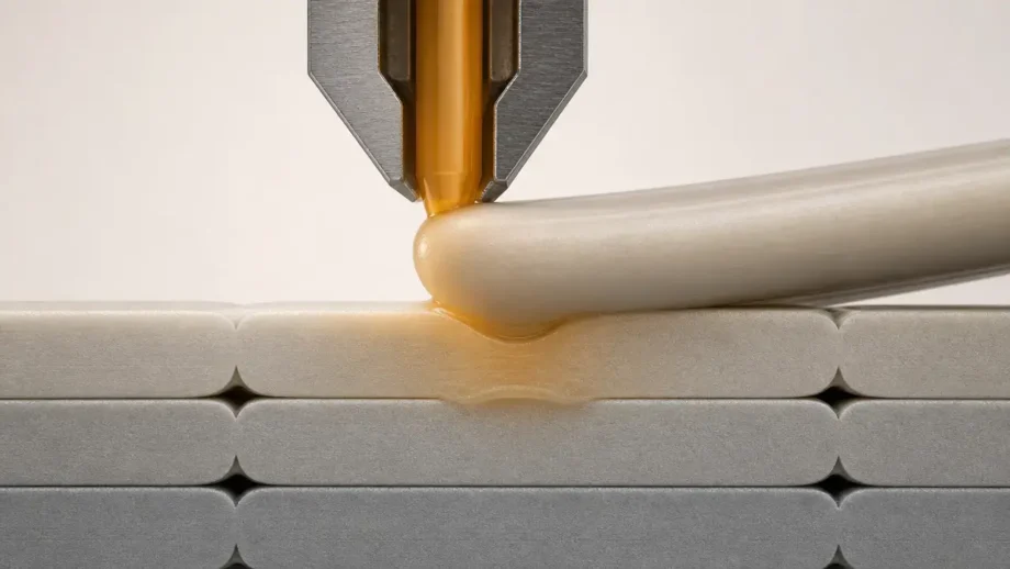
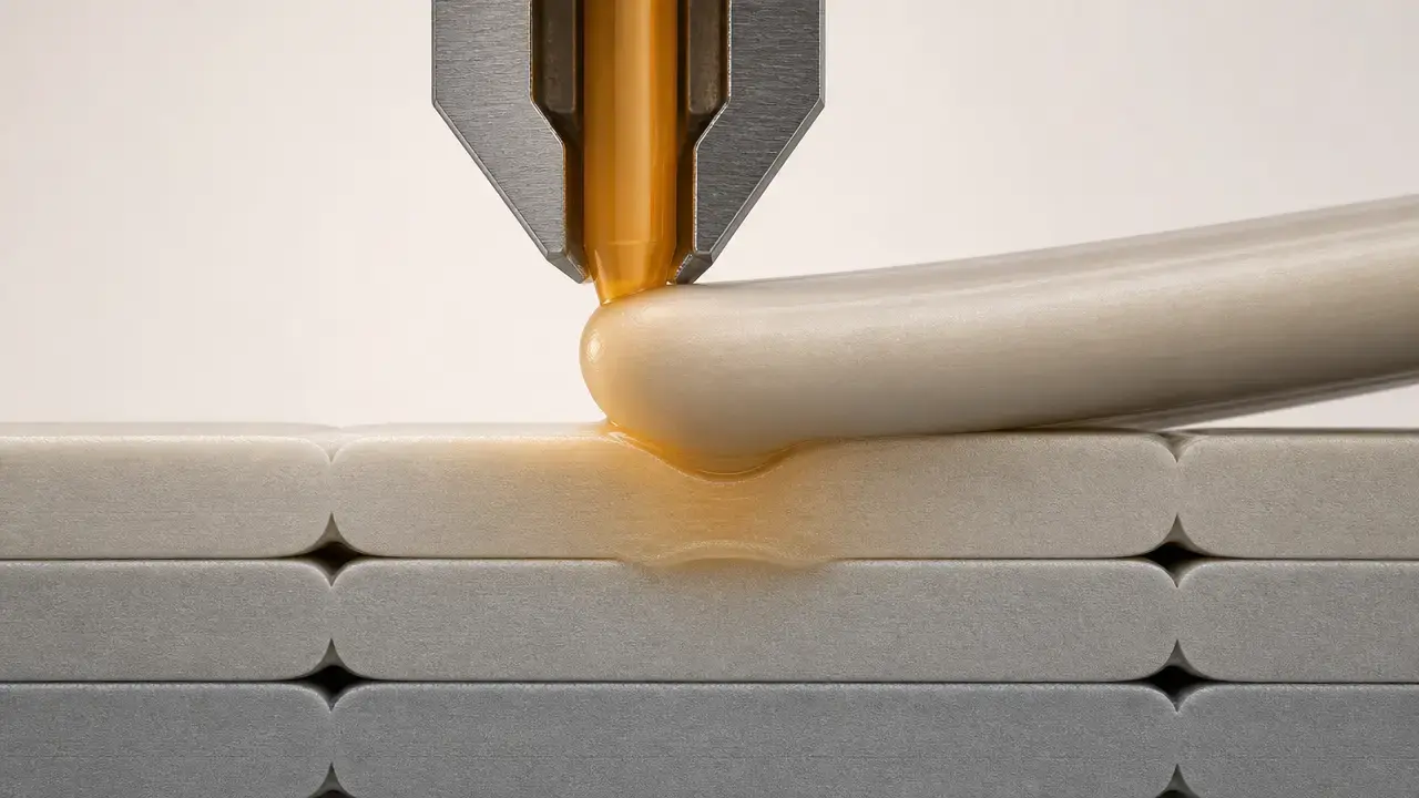
Layer adhesion in 3D printing is the internal interlayer bonding that holds successive deposited roads together in polymer material extrusion, the ISO/ASTM process category in which material is selectively dispensed through a nozzle or orifice. [2]
When that internal bond is weak, prints can split, crack, peel between layers, or fail in a brittle way along the Z direction. But Z-direction failure is not explained by a single setting or a single number. Bond formation depends on contact, temperature history, diffusion time, and voids, while measured part strength also depends on geometry, orientation, porosity, and test method. That is why there is no reliable universal “layer adhesion strength” value that transfers cleanly across printers, materials, and test coupons. [4]
Terms and boundaries
The preferred standards-family term is material extrusion, abbreviated MEX, defined in ISO/ASTM 52900 as additive manufacturing in which material is selectively dispensed through a nozzle or orifice. ISO/ASTM 52900:2021 is Edition 2, published in November 2021, and listed as 28 pages. In hobby use, FFF and FDM are still common labels, but FDM is a Stratasys trademark rather than the generic standards term. [1] [2] [7]
Here, layer adhesion means the bond between printed layers inside the part, not the bond between the first layer and the build surface. Interlayer bonding refers to bonding across adjacent layers; intralayer bonding refers to bonding within the same deposited road or raster. The focus is the internal bond physics and the practical causes of weak layers in printed parts. [2]
Why Z-strength is different: anisotropy without myths
In material extrusion parts, the thermal history is directional. A fresh bead is deposited onto material that has already cooled and partially solidified, so the interface does not experience the same conditions as the material within a single road. That is a main reason printed parts often show higher tensile strength in the X-Y plane and lower strength in Z. It is a useful rule of thumb, but only a tendency, not a universal law. [6]
Weak Z performance also does not automatically prove poor interlayer fusion. Designed PLA tests from Allum and co-authors found that the interface between layers can reach bulk-filament strength, while the apparent anisotropy in the part can still come from filament-scale grooves, local strain concentration, and geometry. NIST’s AM-Bench material-extrusion benchmark points in the same direction by recording shape, voids, mass, tensile properties, and process details together rather than treating “layer bonding” as a single isolated variable. [15] [5]
So a crack that follows layer lines can reflect several things at once: a weaker interface, voids that reduce effective area, or residual stress from uneven cooling and shrinkage. Good troubleshooting starts by separating those possibilities instead of assuming every Z failure is just “not enough heat.” [9] [15]
How interlayer bonding actually forms
Interlayer bonding is a short thermal-mechanical sequence, not a single instant. A newly deposited road has to make intimate contact with the previous layer, form a wider contact region, and then allow polymer chains to diffuse and re-entangle across the interface before mobility falls too far during cooling. In practice, bonding quality depends on both the temperature of the new bead and how long the interface stays able to heal. [14]
What must happen for good interlayer bonding. [14]
- Hot material reaches the previous layer.
- Sufficient contact pressure and contact area develop.
- Enough time remains above an effective bonding temperature.
- Void formation stays limited.
- Extrusion remains consistent.
The mechanism behind that list is well established. Surface contact and neck growth come first; diffusion and entanglement across the interface then build the weld. As the polymer cools toward its glass-transition range, diffusion slows, and high shear in the nozzle can leave chains less able to recover and cross the boundary quickly. A print can look dimensionally acceptable and still have weak layers if the bead arrives too cold, too inconsistently, or with too little time to heal. [14]
Failure-mode taxonomy: what weak layers can mean
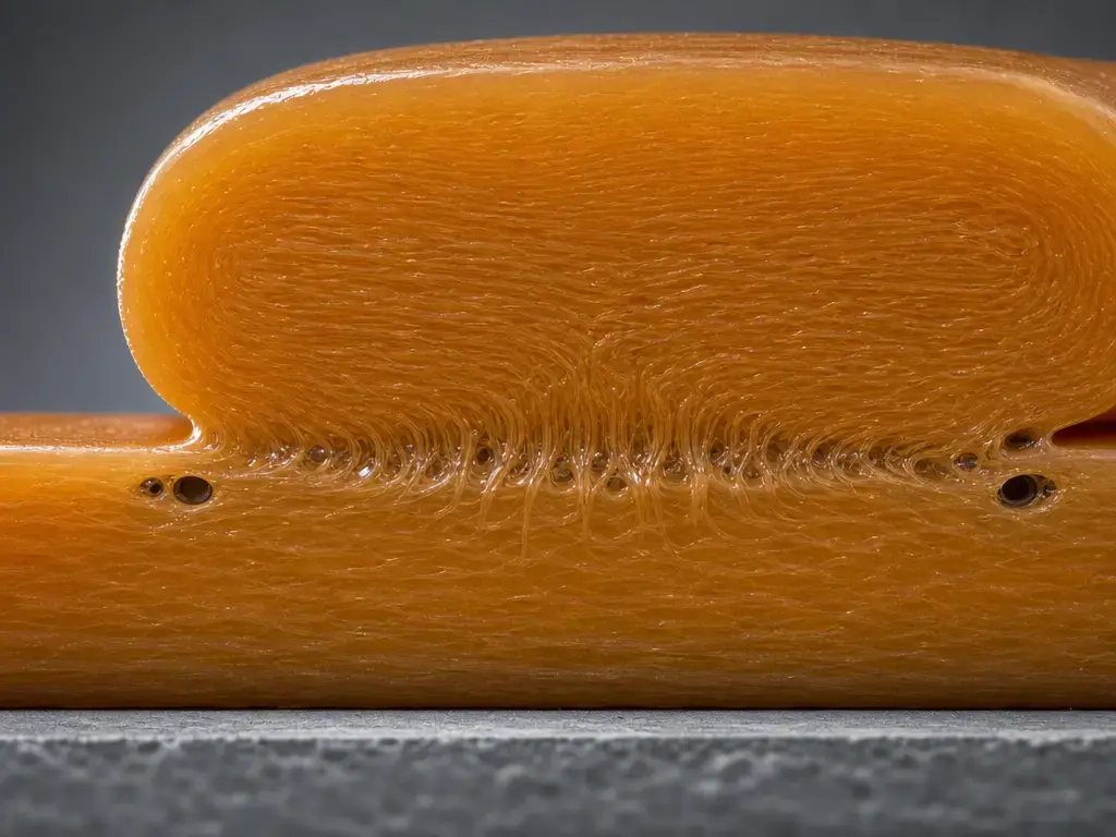
The first failure class is insufficient welding or diffusion. Here the roads touched, but the interface did not fuse deeply enough to carry load. Prusa describes layer separation as delamination mostly caused by wrong temperatures or too much cooling from the print fan or surrounding environment, which fits the classic too-cool, too-fast case. [9]
The second class is defect-driven weakness. Under-extrusion, partial clogs, inconsistent flow, and wet filament reduce real contact area and can create voids or foam-like porosity. In the literature, humidity exposure is also associated with lower mechanical properties and higher porosity for several common printing polymers, so a fracture that looks like bad adhesion may partly be a feedstock problem. [18]
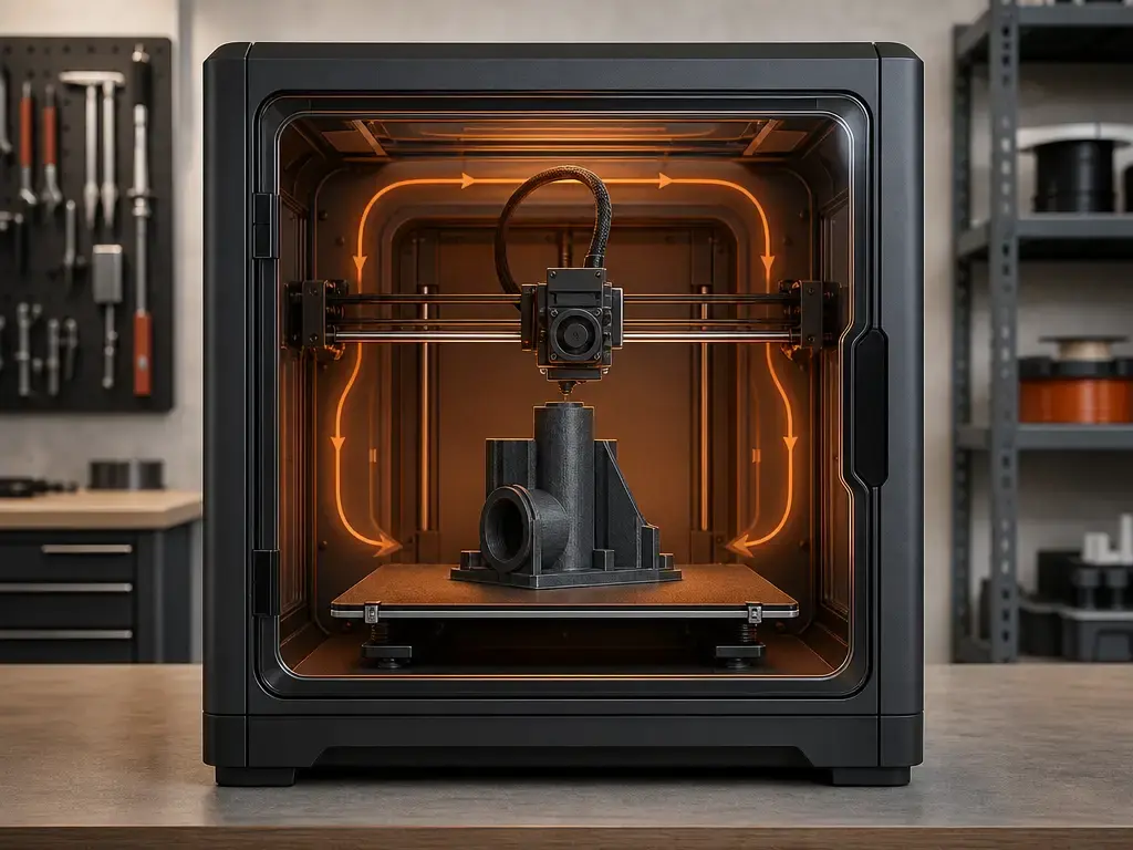
The third class is residual-stress delamination. In that case, the bond may be decent, but shrinkage and thermal gradients pull the part apart after deposition. Prusa explicitly notes that warping forces can exceed layer adhesion strength, which is why ABS and ASA are especially sensitive to drafts and unstable ambient conditions. [9]
| Symptom | Likely mechanism | First adjustment |
|---|---|---|
| Clean break along layer lines | Insufficient welding or diffusion. [9] | Raise nozzle temperature in small steps and retest. [9] |
| Break with visible gaps | Under-extrusion or partial clog. [18] | Check nozzle condition and flow consistency first. |
| Foamy or pitted fracture surface | Moisture-driven porosity. [18] | Dry the filament and retest from sealed storage. [18] |
| Mid-height splitting on ABS or ASA | Drafts or thermal gradients. [9] | Reduce part cooling and block ambient drafts. [9] |
| Corners lift, then a split propagates | Warping stress exceeded bond strength. [9] | Improve enclosure or thermal stability. [9] |
| Weakness only in one area | Local cooling or local flow inconsistency. | Compare fan exposure, path speed, and extrusion in that region. |
| Rough, brittle-looking layer interface | Poor contact plus voids. [14] | Improve extrusion consistency before chasing extreme temperatures. [14] |
Weak layer adhesion causes
The most common causes are thermal. If the nozzle temperature is too low, the interface does not stay mobile long enough for strong healing. If the part-cooling fan, room airflow, or a cold ambient environment removes heat too quickly, the same failure can appear even when the displayed nozzle number looks normal. Prusa’s troubleshooting guidance for PLA gives a broad working range of 195–220 °C depending on brand and recommends moving in 5 °C steps when diagnosing layer separation. [9]
Throughput and geometry matter next. A hotend can be set to a reasonable temperature and still underdeliver if line width, layer height, or speed push melt demand too high. Geometry also affects contact area: the PrusaSlicer manpage states that maximum recommended layer height is 75% of extrusion width for reasonable inter-layer adhesion. That does not mean every thinner layer is automatically stronger, but overly tall layers leave less forgiving bead geometry at the interface. [13]
The third cluster is material delivery and condition. Flow calibration, extrusion multiplier, partial clogs, wet filament, and unstable ambient conditions can all reduce effective bond area or add voids. A practical way to troubleshoot is to change one variable at a time on a small coupon instead of a full print. Prusa also suggests adjusting extrusion multiplier or flow in 5% increments when interlayer bonding looks weak. [9] [18]
- Confirm that the failure is internal layer adhesion, not a first-layer problem.
- Check the filament’s known working range and your current profile first. [9]
- Increase nozzle temperature in a small step, such as 5 °C, and retest the same simple coupon. [9]
- Reduce part cooling in a small step and retest the same coupon. [9]
- Lower print speed or volumetric demand in a small step and retest. [13]
- Increase flow or extrusion multiplier in a small step, such as 5%, and retest. [9]
- Inspect filament dryness, nozzle health, and the local print environment. [18]
- If the issue persists, reduce layer height or redesign for more contact area at the interface. [13]
Speed vs flow vs volumetric flow
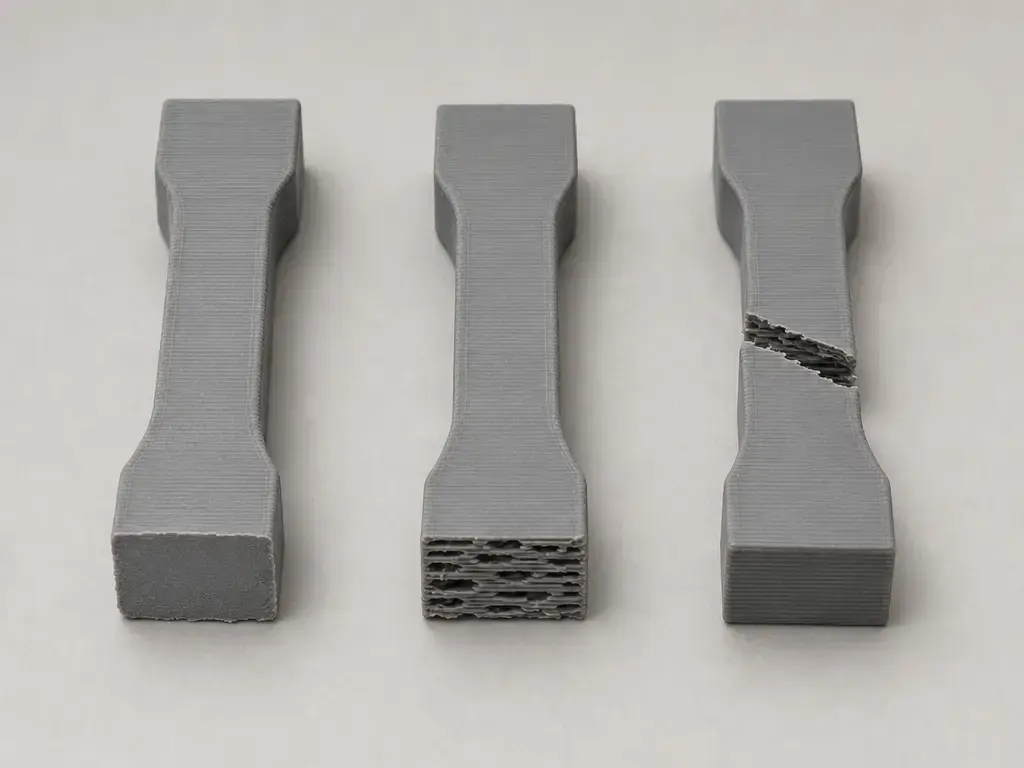
Print speed is the motion rate of the nozzle, usually in mm/s. Flow or extrusion multiplier is the slicer-side scaling of how much material is pushed relative to the planned toolpath, usually expressed as a percentage. Volumetric flow is the melt demand on the hotend, conceptually in mm³/s, and it rises when you increase speed, line size, or layer size. PrusaSlicer includes a max volumetric speed setting because these are related but not interchangeable: you can keep a “normal” speed value and still outrun melt capacity if the bead cross-section is large enough. When that happens, the printer may deliver an unstable, under-softened bead, and layer adhesion can fall apart even though the nominal temperature looks reasonable. [13]
How to get better layer adhesion
If you want to know how to get better layer adhesion, the short answer is to improve contact, protect thermal time at the interface, and avoid creating voids. The best layer adhesion 3D printing settings are the ones your material and hotend can sustain consistently, not simply the hottest or fastest numbers on a spec sheet. [14]
Temperature is usually the first lever, but higher is not always better. More heat can improve diffusion and welding, yet the same review literature warns that excessive printing temperature can promote degradation, volatile release, bubble formation, and flow instability when viscosity becomes too low. That is why temperature changes should be small and judged against fracture behavior and print quality together. [14]
Cooling and throughput shape the same bonding window from the other side. More part cooling shortens the time the interface stays compliant; more throughput can push the hotend past stable melt delivery. If you are near that limit, reduce print speed or cap volumetric demand before chasing large temperature increases. Flow calibration matters too, because even a thermally adequate bead cannot bond well if it is undersupplied. [13] [14]
Geometry and material handling finish the job. Staying within PrusaSlicer’s 75%-of-extrusion-width guideline for maximum layer height helps avoid contact geometry that is hard to fuse reliably. Line width, nozzle size, and path consistency all influence the real bonded area between layers. Drying and sealed storage also matter, because published review data links humidity exposure to property loss and increased porosity across several common FFF polymers. For draft-sensitive materials, enclosure use and ambient stability are often more effective than dramatic slicer changes. [13] [18] [9]
Material effects
Typical hobby-print tendency under suitable settings; outcomes depend on brand, additives, printer, and test method. [4]
Practical material comparisons are useful, but they are never universal rankings. ASTM F3489-23 explicitly notes that reported properties vary with material choice, anisotropy, storage and preparation, porosity, orientation, build-plate location, testing environment, gripping and alignment, test speed, and test temperature. That is why a claim such as “PETG has better layer adhesion than PLA” is only meaningful if the profile, geometry, and test are named. [4]
| Material group | Typical layer-bonding tendency (conditional) | Helpful controls | Main caution |
|---|---|---|---|
| PLA | Often good if the interface is not over-cooled. [9] | Moderate heat and controlled fan use. Prusa baseline example: 215 °C first layer, 210 °C other layers, 60 °C bed. [10] | Brittle failure can still make weak Z behavior look worse than it is. |
| PETG | Often described as a strong layer-bonding hobby material. [11] | Adequate heat and careful fan use. Prusa baseline example: 230 °C first layer, 240 °C other layers, 85 °C first-layer bed, 90 °C later layers. [11] | Stringing and strong bed adhesion can complicate tuning. [11] |
| ABS/ASA | More draft-sensitive; delamination risk rises with cold air and uneven cooling. [9] | Enclosure, low part cooling, stable ambient conditions. [9] | Warping and odor management matter. [9] [16] |
| Nylon/PC | Often capable, but usually more sensitive to moisture and thermal control in hobby use. [18] | Dry filament and stable warm surroundings. [18] | Hygroscopic behavior and profile sensitivity. [18] |
| Filled/CF/GF blends | Often stiffer, but not automatically better in Z. [14] | Drying, conservative throughput, and hardware suited to abrasive filaments. [14] | Higher viscosity can worsen clogging, stringing, warping, or wetting. [14] |
For PLA vs PETG layer adhesion strength, the defensible answer is conditional. PETG is widely described as having good layer adhesion, and Prusa’s PETG guidance notes that reducing the print fan can improve toughness, but ASTM’s variability warning still applies: profile, cooling, geometry, and test method can easily change which material looks better on a given printer. [11] [4]
Filled and reinforced materials need even more caution. ISO/ASTM 52903-1 exists because plastic feedstock definition and qualification are part of the process, including unfilled, filled, and reinforced plastics. Review literature also warns that filled filaments can raise melt viscosity and increase the risk of clogging, stringing, and warping. A 2024 CF-PLA study reported one study-specific optimum at 5 wt.% carbon fiber, 0.1 mm layer thickness, 60 °C bed temperature, 40 mm/s print speed, and 215 °C nozzle temperature, but that is an example of parameter dependence, not a universal recipe for stronger Z bonds. [3] [14] [17]
Performance metrics: what people mean by Z-strength
“Z-strength” is a convenient shorthand, not a single standardized property. People may mean Z-oriented tensile performance, a bending result, fracture behavior, or a shear-dominated test. Those do not interrogate the same failure mode, and a printed part can fail by interface separation, filament rupture, or void-driven stress concentration depending on the specimen and loading. [4] [5]
This is why recording conditions matters as much as the number itself. ASTM F3489-23 says reported properties are influenced by material, anisotropy, storage and preparation, porosity, orientation and build location, environment, alignment and gripping, test speed, and test temperature. Interlaminar shear is a useful complement because it probes a different failure mode: the ASTM D2344/D2344M-22 short-beam context specifies a span length-to-thickness ratio of 4.0 and a minimum thickness of 2.0 mm, which shows how strongly test geometry shapes the result. [4] [19]
ABS and ASA troubleshooting block
ABS layer adhesion is mostly a thermal-stability problem. Prusa says ABS is highly susceptible to layer separation when cold air hits the print, recommends turning fans off for ABS, and says ABS is best printed in an enclosed chamber. In practice, that means reducing part cooling, minimizing drafts, and keeping the bed and surrounding air as steady as possible while layers accumulate. If you use manufacturer profile numbers, treat them as ecosystem-specific examples only: Bambu’s ABS page lists drying at 80 °C for 8 h, sealed storage below 20% RH, nozzle temperature of 240–270 °C, and bed temperature of 80–100 °C. [9] [16]
When reducing cooling for ABS or ASA, the target is the part-cooling fan, not the hotend’s normal thermal management. Ventilation still matters: Bambu warns that pungent odors may be released during ABS printing and recommends a well-ventilated area. [16]
Optional post-processing with guardrails
Annealing or similar post-processing can sometimes improve selected properties, but it should be treated as optional follow-up, not the main cure for poor interlayer bonding. If a part is weak because the bead arrived too cold, too sparse, or too wet, post-processing does not erase the original printing defect. [4]
If you do anneal, re-check dimensions and fit afterward. As ASTM-style reporting makes clear, properties are process- and context-dependent, so post-processing results are not universal across materials, geometries, or print histories. [4]
Bed adhesion vs layer adhesion
Bed adhesion is the bond between the first layer and the build surface; layer adhesion is the bond inside the finished part. Prusa’s first-layer guidance is a separate topic and includes reducing speed to about 75% for the first three layers and raising heatbed temperature by 5–10 °C for unfamiliar materials that do not stick well. [12]
Practical takeaways for layer adhesion in 3D printing
Layer adhesion in 3D printing improves when you protect the short window in which a fresh bead can contact, flatten, diffuse, and cool without leaving large voids. In practice, that means using enough heat, not too much fan, manageable throughput, dry material, and a part orientation that does not force every critical load through the weakest path. [14] [13] [18]
- Heat: Raise nozzle temperature only enough to improve bonding. [9] [14]
- Cooling: Reduce part cooling when the interface is freezing too fast. [9]
- Flow and throughput: Respect volumetric limits and avoid overly tall layers. [13]
- Drying: Dry and store filament properly when moisture is adding porosity. [18]
- Design and orientation: Rotate or redesign parts when the main load would otherwise follow weak Z paths. [6] [15]
FAQ
What is layer adhesion in 3D printing, and how is it different from bed adhesion?
Layer adhesion is the internal bond between successive printed layers inside the part. Bed adhesion is only the bond between the first layer and the build surface, so a first-layer fix does not automatically solve mid-print splitting or brittle Z-axis failure. For first-layer issues, Prusa treats slower first layers and modest bed-temperature increases as a separate troubleshooting path. [12]
Why are my prints splitting between layers halfway up?
That symptom usually points to cooling, thermal-gradient, or flow problems rather than random variation. Too much part cooling, low interface temperature, moisture-driven porosity, or a cold draft hitting the print can all create mid-height separation, especially in ABS- or ASA-like materials where warping stress can exceed layer adhesion strength. [9] [18]
How do I get better layer adhesion without ruining detail?
Work in small steps. Slightly raise nozzle temperature, reduce part cooling only as much as needed, and keep volumetric demand within what the hotend can actually melt and deliver. That protects the bonding window without jumping straight to settings that cause bubbles, sagging, or unstable flow. [13] [14]
Does PETG have better layer adhesion than PLA?
Sometimes, but not always. PETG is often described as having strong layer bonding, and its ecosystem-specific profiles usually run hotter than PLA, but ASTM-style reporting makes clear that the comparison still depends on geometry, cooling, orientation, and test method. Treat “PETG is stronger between layers” as a printer-and-profile-specific result, not a law. [11] [4] [10]
Expert: What is the difference between Z-tensile strength and interlaminar shear strength for FFF parts?
A Z-tensile-style result pulls the part apart across the layer stack, while interlaminar shear tries to provoke sliding or shear-dominated failure between layers. Those tests emphasize different stress states, so the same print can look acceptable in one and weak in the other. ASTM D2344’s short-beam setup is a reminder that geometry and failure mode are part of the measurement itself. [19] [4]
Expert: How can volumetric flow limit interlayer bonding even if temperature looks correct?
Because the displayed nozzle temperature does not guarantee that enough fully melted polymer is arriving at the interface. If speed, line width, or layer height demand more melt than the hotend can supply, extrusion becomes inconsistent or under-softened, and the bead cannot make or keep a good weld. That is the practical reason slicers expose a max volumetric speed setting. [13] [14]
Are carbon-fiber or other filled filaments automatically better for Z-strength?
No. Filled filaments can improve stiffness or other properties, but they can also raise melt viscosity and make wetting, flow consistency, and clog resistance worse. The safer conclusion is that composites are more parameter-sensitive, not automatically better at interlayer bonding. [14] [17]
Sources
- ISO/ASTM 52900:2021 listing (metadata)
- ISO/ASTM 52900 definition excerpt (MEX definition)
- ISO/ASTM 52903-1:2020 listing
- ASTM F3489-23 listing
- NIST AM-Bench AMB2018-03 description
- Stratasys Direct: Balanced Design key factors
- Stratasys Legal Information (FDM is a trademark)
- Justia trademark mirror: FDM details
- Prusa: Layer separation and splitting (FDM)
- Prusa: PLA material guide
- Prusa: PETG material guide
- Prusa: First layer issues
- PrusaSlicer manpage (max layer height, max volumetric speed)
- Materials (2023) FDM thermoplastic filaments overview (welding/diffusion, filled filament viscosity caveat)
- Allum et al. Interlayer bonding has bulk-material strength in extrusion additive manufacturing
- Bambu Lab ABS page (drying/settings + ventilation note)
- Polymers (MDPI) CF-reinforced PLA composite paper (example optimization)
- Polymers (MDPI) review on operating conditions + humidity effects
- ASTM D2344/D2344M-22 store listing
- Polymers (MDPI) PLA interlayer adhesion temperature study (Liparoti et al.)