
Summary
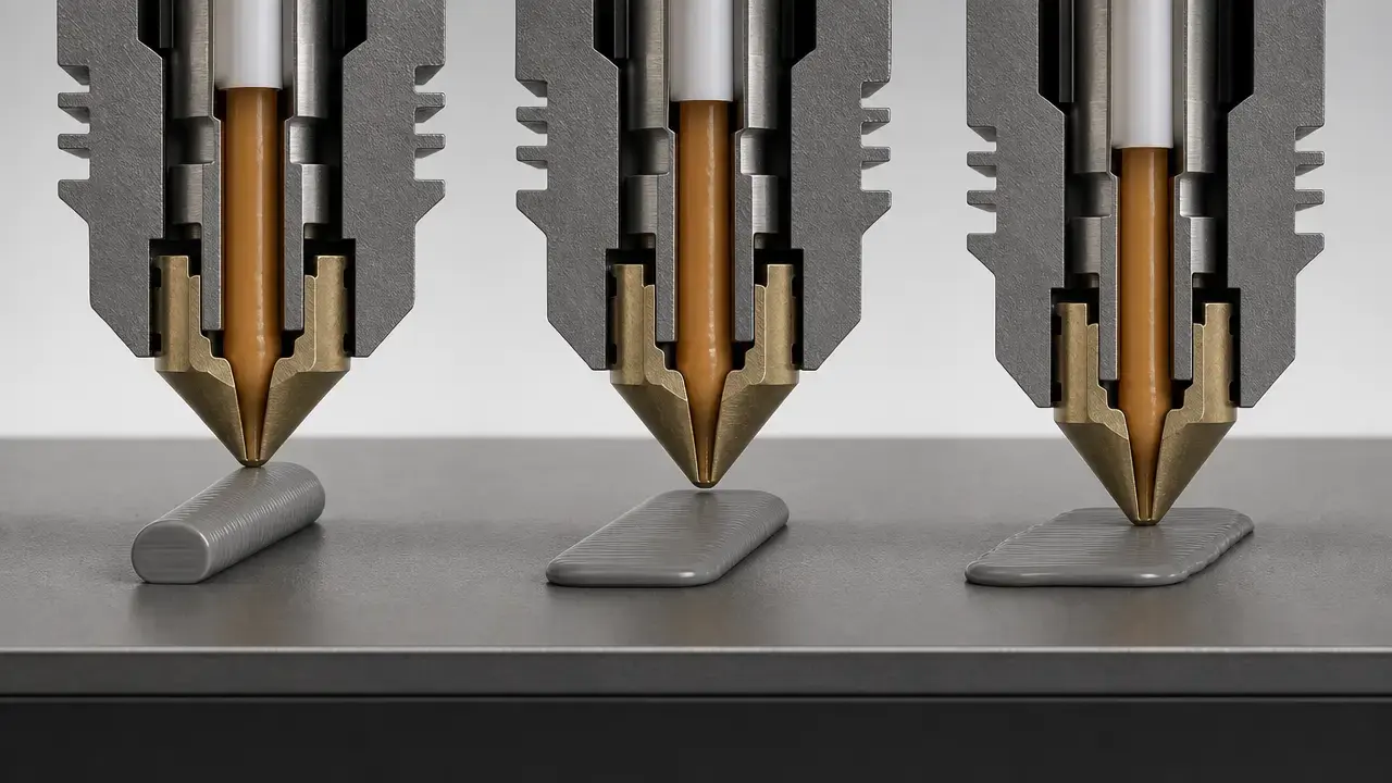
First layer adhesion is the successful attachment of the first deposited polymer layer to the build surface in material extrusion printing, the additive manufacturing process family that standards and government sources describe as building material layer by layer. [1] [3]
In desktop printing, that usually means the FDM or FFF first layer on a removable plate, sheet, or other build surface. The problem is not simply “make it stick more.” A good first layer balances geometry and interface conditions: the nozzle gap and bead shape must create enough contact, while cleanliness, surface compatibility, temperature, and later shrinkage stresses must not overpower that bond. Resin printers are outside the scope here because vat photopolymerization cures liquid resin with UV light and uses a different build sequence rather than extruding a bead onto a plate. [1] [2] [3]
Quick term map
In hobby use, readers often hear FDM or FFF, while standards and government sources place the same desktop family under material extrusion. ISO/ASTM 52900:2021 is Edition 2, was published in 2021-11, is 28 pages long, and was reviewed and confirmed in 2025 (standard). Stratasys also states that FDM is a trademark of Stratasys, Inc., so it is better treated as a common industry term with a trademark boundary, not as the standards name for the whole process family. [1] [3] [4]
Scientific literature also uses “FFF or FDM” for this extrusion-based, layer-by-layer process, so both terms are familiar to readers even though material extrusion is the cleaner umbrella label. CuraEngine documentation adds another term people often confuse with adhesion itself: “Initial Layer Height” is a slicer command, not a guarantee of the bead you will physically get on the plate. [5] [6]
| Term | What it means here |
|---|---|
| First layer adhesion | Bonding of the first deposited layer to the build surface. Interlayer adhesion is bonding between later layers inside the printed part. [6] |
| Bed leveling | Making the print plane consistent relative to motion so the gap is predictable across the bed. Z offset is the nozzle-to-bed distance adjustment on top of that reference. [7] [8] |
| First layer height | The slicer’s commanded first-layer Z behavior or “Initial Layer Height.” Actual first-layer thickness is the bead you really deposit after flattening and flow effects. [5] [7] |
| Squish | How much the bead is flattened by the nozzle gap. It is not the same as over-extrusion, though the two can look similar. [7] [12] |
| Adhesion failure | The line never bonds well enough in the first place, so it drags or lifts immediately. Warping is later lift driven by cooling and shrinkage stress after initial sticking. [6] [8] |
| FDM/FFF | Reader-facing desktop terms for this extrusion family, with FDM a Stratasys trademark. Material extrusion is the standards-oriented umbrella term. [1] [4] [6] |
Why the first layer controls the print
The first layer is the foundation for everything above it. If that base never bonds properly, later layers cannot fix it; they only add weight, thermal history, and leverage that make the failure more obvious. Spoerk et al. describe the first printed layer as the foundation for subsequent layers and note that inadequate adhesion leads to poor print quality, warping, or delamination. [6]
Three mechanisms matter, and separating them helps with diagnosis. First, wetting and contact quality determine whether the hot polymer can form a good interface with the surface at all. Second, bead geometry determines the mechanical contact area, so nozzle gap, line width, and first-layer squish affect how much of the bead actually touches the plate. Third, even a line that initially sticks can later lift when the part cools and shrinkage stress rises. In Spoerk et al.’s lab setup, PLA on PI rose from 51 ± 8 N to 322 ± 47 N, and PLA on glass rose from 73 ± 19 N to 651 ± 17 N, when bed temperature increased from 60 to 70 °C around PLA’s 60.6 °C glass transition temperature (lab study). [6]
The opposite failure also matters: too much adhesion can be a problem. Prusa warns that PETG on smooth PEI can adhere too strongly and may damage the sheet, which is a useful reminder that the goal is controlled adhesion, not maximum adhesion. [11]
The mechanics: nozzle gap, Z offset, bed leveling, and squish
Nozzle gap is the actual distance between the nozzle tip and the build surface during the first layer. Z offset is the adjustment used to shift that relationship, and bed leveling or mesh compensation is the printer’s attempt to keep that relationship consistent across the plate. Because sensors, nozzles, and sheet thicknesses differ, a copied offset value is not portable from one machine to another. Prusa explicitly says the numeric value is unique to each machine, visually calibrated, and only loosely falls into a common range such as -0.400 to -1.500 (vendor example). [7]
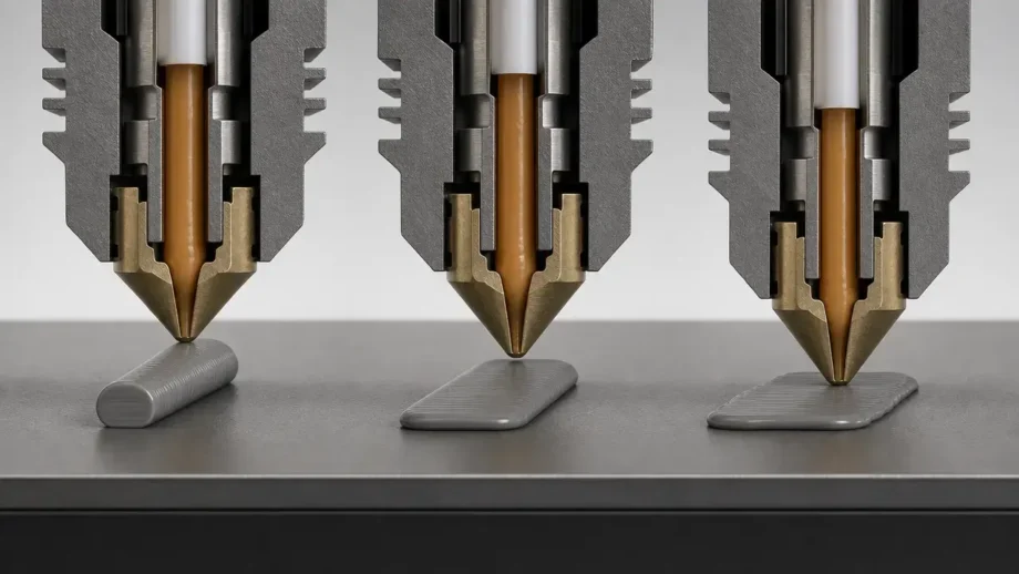
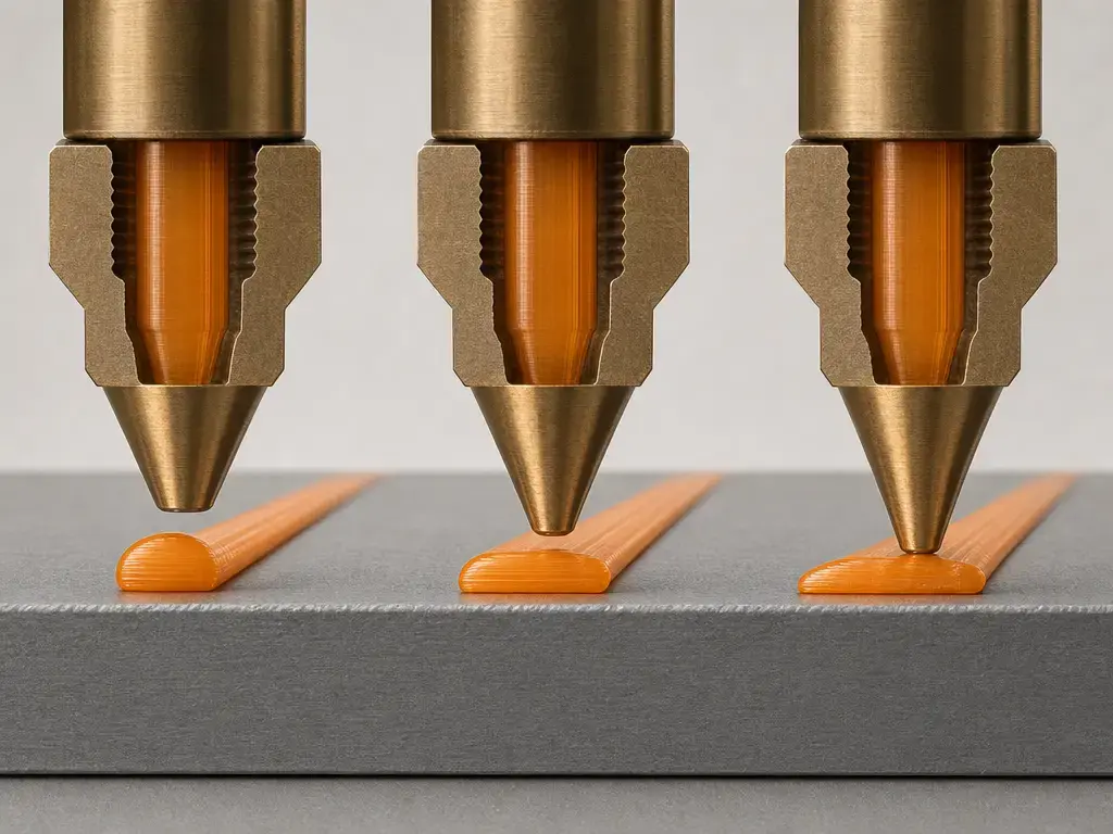
Squish is the flattening of the extruded bead against the plate. Vendor troubleshooting patterns are useful here, but they are still heuristics, not laws of physics. Bambu groups first-layer symptoms into “not sticking,” “too low,” and “too high or sparse,” while Prusa’s first-layer guide shows the visual difference between rounded lines with gaps and over-compressed lines with ridges or even nozzle scraping. [7] [8]
Flow and gap also interact. If extrusion flow is too high, the line can become overly wide and mimic a nozzle that is too low; if flow is too low, a good gap can still look sparse. That is why first-layer diagnosis should not stop at “more squish” and should also check extrusion consistency and nozzle condition. [8] [12]
Good first layer visual checklist:
- Continuous lines that stay attached as the nozzle moves. [7] [8]
- No visible gaps between adjacent lines in the filled area. [7] [8]
- Mild flattening rather than round strings or paper-thin transparency. [7]
- No ridges, plowed edges, or obviously over-compressed tracks. [7] [8]
- No scraping, dragging, or clicking that suggests the nozzle is too low or extrusion is failing. [7] [8]
Commanded first-layer height vs actual first-layer thickness
This distinction causes a lot of confusion. What the slicer commands is a motion plan and a nominal first-layer height, not the exact bead you will end up with on the bed. In CuraEngine’s example, the first layer spans 0 to 0.27 mm, is sliced at 0.135 mm, and the machine is told to move to Z0.27 before printing that layer. CuraEngine also documents a separate “Initial Layer Height” for the first layer (slicer documentation). [5]
The real bead is different because the nozzle is pushing molten polymer onto a surface, not placing a perfect rectangular slab in empty space. A simple way to picture it is this: the slicer commands a height, the nozzle deposits a roundish strand, and that strand is flattened into a wider, thinner footprint depending on gap, surface contact, and flow. That is why commanded first-layer height settings and actual first-layer thickness are related, but not identical. Prusa also notes that a single layer is about 0.2 mm / 0.00787402 inch and that calipers are not a recommended way to calibrate the first layer, because thickness alone does not tell you whether the interface is good. [7]
A profile example helps, as long as it stays a profile example. Prusa says its print profiles use 0.20 mm as the first-layer height and warns that changing that value will likely require recalibration. The same page also says layer height should stay below 80% of nozzle diameter, which is about 0.32 mm for a 0.4 mm nozzle (vendor example). [10]
Calibration workflow: from clean plate to a perfect first layer
A repeatable workflow is more useful than universal numbers. Start with the correct plate and material profile, assume the surface may be contaminated, and stop early if the printer is clearly scraping or failing instead of hoping the print will recover. [7] [8] [9]
- Inspect the nozzle for damage, residue, or signs of partial clogging before you trust any first-layer test. [9] [12]
- Heat the printer to normal printing temperatures for the filament and profile you actually plan to use. [9] [11]
- Clean the plate with a plate-appropriate method: Prusa recommends 90% IPA as a vendor example, while Bambu advises warm water and a neutral detergent for not-sticking cases. [8] [9]
- Respect surface-specific solvent limits: Prusa says acetone is for smooth PEI only, around once per month, not on textured or satin sheets, and not before printing PETG. [9]
- Run leveling or mesh compensation if your printer offers it. [8] [9]
- Print a simple single-layer test and watch the lines, not just the screen number. [7]
- Live-adjust Z while the test is printing until lines are connected and mildly flattened. Bambu’s X2D manual gives a “set the gap to 0.02, then print a test” instruction, but the manual does not state a unit, so it should be treated only as a device-specific interface value, not a universal millimeter target (vendor example). [7] [8]
- Stop immediately if you hear scraping, see no extrusion, or watch the nozzle drag loose lines around the plate. [7] [8]
Re-run the process after any major change. Prusa says first-layer calibration should be repeated after nozzle changes, extruder upgrades or other axis-related changes, and after moving the printer to a different location. [7]
Troubleshooting by failure mode
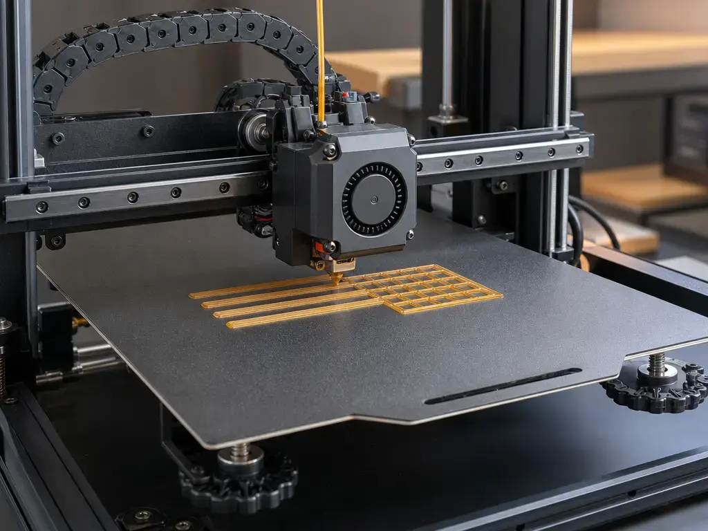
A useful troubleshooting method is to ask when the failure happens. If the line never bonds during deposition, start with cleanliness, surface compatibility, leveling, and gap. If the part starts well and only later curls at the corners, that points more strongly to thermal stress and warping than to an immediately bad interface. [6] [8] [9]
These are first-check heuristics, not certainty. Multiple causes can overlap, especially when a borderline gap, marginal plate cleanliness, and weak thermal settings all exist together. [7] [8] [12]
| Failure mode (when) | What you see | Most likely causes | First actions |
|---|---|---|---|
| Immediate: won’t stick / dragged lines | Thin, wavy, dragged lines that shift or detach. [8] | Dirty or mismatched plate, no leveling, nozzle too high. [8] | Clean plate, confirm plate-material match, rerun leveling, lower gap if lines are thin and rounded. [8] [9] |
| Immediate: too-low gap / over-squish | Very wide lines, ridges, scraping, flattened surface. [7] [8] | Nozzle too close, bad leveling, or a flow setting that mimics too much squish. [7] [12] | Raise the gap slightly, check leveling, verify extrusion behavior. [7] [8] |
| Immediate: too-high gap / sparse lines | Rounded lines, gaps between tracks, loose first layer. [7] [8] | Nozzle too far from bed, poor spread of the bead. [8] | Lower the gap, print another single-layer test, watch for continuous surface formation. [7] [8] |
| Later: sticks, then corners lift | Corners rise after several layers or later in the print. [6] | Thermal shrinkage stress, draft exposure, insufficient contact area, marginal bed temperature. [6] [12] | Add contact area with a brim, reduce early cooling, and adjust temperature only after the base interface is already sound. [9] [12] [13] |
| Removal: sticks too strongly / surface risk | Part is hard to remove or risks plate damage. [9] [11] | PETG on smooth PEI, PETG after IPA cleaning, or no barrier layer on a strong-bond surface. [9] [11] | Use a barrier or release layer such as glue stick where the plate maker recommends it, and reconsider the plate-surface choice. [9] [11] |
Build plate surfaces, cleaning, and adhesion aids
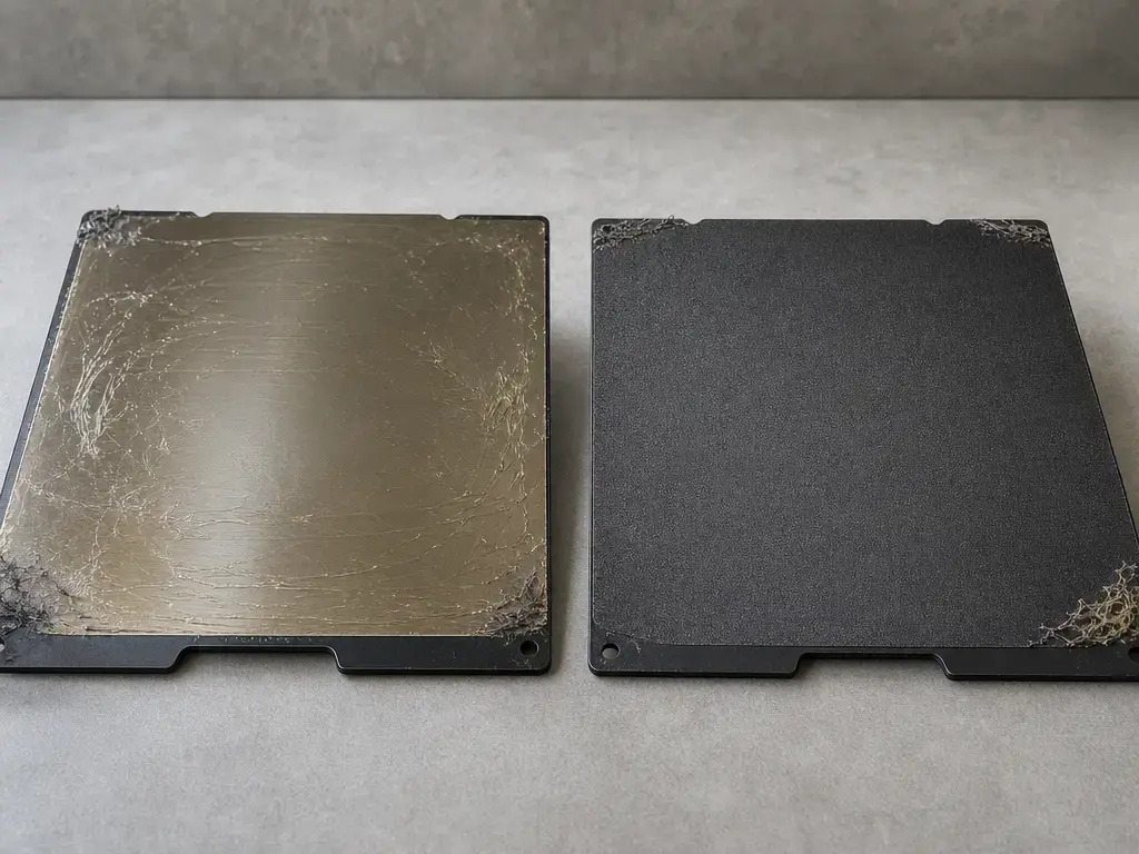
The build surface is the interface the polymer must wet, grip, and later release from. Compatibility matters more than chasing the stickiest possible surface. The practical question is not which bed is best, but which surface gives controlled adhesion for a given material on a given printer. [6] [9] [11]
For cleaning, stick to source-backed methods. Prusa recommends 90% IPA as a vendor example and says acetone should be used only on smooth PEI, only around once per month, never on textured or satin sheets, and not before printing PETG. Bambu’s X2D manual advises warm water and a neutral detergent for first-layer-not-sticking cases. Those instructions are not interchangeable chemical rules for every surface on the market, but they show the main principle: cleaning and solvent compatibility depend on the exact plate coating. [8] [9]
Some adhesion aids are used mainly as release or barrier layers to prevent damage or over-adhesion. That is common with PETG on some smooth surfaces: Prusa warns that IPA plus PETG can cause very strong adhesion, and its PETG guide says smooth PEI can be damaged and recommends glue stick if that surface is used anyway. [9] [11]
Temperature, speed, cooling, and material effects
Temperature changes both the interface and the later stress state. In Spoerk et al.’s lab study, bed temperature was swept from 30 to 120 °C in 10 K steps, with die temperatures of 220 °C for PLA and 255 °C for ABS, while first-layer thickness was held at 0.2 mm. Their results support the broad idea that bed temperature can strongly influence first-layer adhesion, but the paper is evidence about mechanism under a defined test method, not a plug-in recipe for consumer printers. [6]
Speed and cooling act more indirectly. Prusa suggests dropping speed to about 75% for the first three layers as a vendor example, while the MDPI troubleshooting review explains that a first-layer speed set to 50% means the first layer prints 50% slower than the rest. The same review gives “disable the cooling fan for the first few layers” and “increase the nozzle temperature by 5 °C” as troubleshooting examples, not universal defaults. [9] [12]
Use those levers only after the basics are under control. Prusa also suggests increasing bed temperature by 5-10 °C when experimenting with a new material that does not adhere well, but that is a vendor example for careful iteration, not a rule that overrides a dirty plate, a wrong gap, or a mismatched surface. [9]
Brim, skirt, and raft: what they are and what they are not
A skirt is a printed outline made before the model, mainly to stabilize filament flow and verify first-layer behavior. Prusa also notes that because the skirt prints before the model, it is a good moment to adjust Live Z if the first layer is not sticking or is too squished. A brim is different: it expands the surface area of the first layer around the object, which is why Prusa recommends it for tall objects with a small base or multiple small objects at once. A raft is a separate printed platform under the part; MakerBot’s patent defines it as a platform fabricated prior to the object to provide a consistent surface on which to initiate fabrication. [13] [14]
What these structures do not do is fix a dirty bed or a badly set nozzle gap. Use a skirt for priming and diagnosis, a brim for extra contact area when the part footprint is small or warping-prone, and a raft when you need an intentionally sacrificial printed interface. [13] [14]
PETG case study: why settings advice is not portable
When PETG first-layer adhesion is weak, the usual suspects are still surface contamination, too much gap, wrong surface choice, or cooling that is too aggressive for the situation. The important point is that PETG settings are not portable between printers and surfaces, so diagnosis should start with the same workflow used for any material, not with copied community numbers. [8] [11] [12]
When PETG sticks too strongly, the surface choice becomes central. Prusa warns not to print PETG on smooth PEI because adhesion may be too strong and the sheet may be damaged. It also warns that IPA plus PETG can make removal extremely difficult. This is where barrier layers matter more than extra stick: glue stick can be used not only as an adhesion aid, but as a controlled release layer. [9] [11]
Vendor examples show why a single PETG recipe is misleading. Prusa’s PETG page lists 230 °C nozzle for the first layer, 240 °C for later layers, 85 °C bed for the first layer, and 90 °C for later layers (vendor example), while Bambu’s PETG Basic TDS V3.0 lists 230-260 °C nozzle, 65-75 °C bed, 0-60% cooling fan, and printing speed under 200 mm/s (vendor example). Those numbers describe different ecosystems, not a universal PETG rulebook. [11] [15]
Limits of adhesion numbers
A visually good first layer is necessary, but it cannot compensate for unrelated faults such as nozzle contamination, unstable extrusion, a loose hotend, or a profile that does not match the hardware. First-layer diagnosis works best when it is paired with a basic extrusion sanity check instead of assuming every failure is a Z-offset problem. [8] [9] [12]
Lab adhesion numbers are also highly method-dependent. Spoerk’s measurements came from a very specific setup: 16 strands, each 100 mm long, three layers tall for 0.6 mm total height, about 1.65-1.9 mm wide and 12 mm apart; a shearing block passed 0.1 mm above the bed at 2 mm/s, data were sampled at 300 Hz, and maxima from 16 strands were evaluated at 5% significance (lab study). [6]
That is why Laumann et al.’s scope statement matters. Their 2022 paper says there is no established method to measure adhesion of printed parts, and the device they describe is itself a specialized system that can work up to 400 °C nozzle temperature and around 150 °C build-platform temperature and costs about 1700€ (lab study). In other words, science can measure bed adhesion, but there is no single printer-independent consumer number that tells you your own first layer is correct. [16]
Current research
Bhavsar et al. show one monitoring direction: using inexpensive sensors and discrete wavelet analysis to distinguish vibroacoustic signals from successful versus failed first-layer deposition. That is promising because it tries to detect bad bonding during the act of laying down the first layer, not after the print has already failed. [17]
In a research prototype, Guidetti et al. reported closed-loop line-width control from 33% to 233% of nozzle diameter and disturbance rejection for bed-leveling errors at layer heights from 20% to 200% of nominal. This is not a consumer-printer setup or recommended calibration target. Werkle et al. describe another direction: camera-based monitoring that compares the actual contour of a layer with the target contour derived from G-code processing. [18] [19]
Key takeaways: first layer adhesion without guesswork
First-layer adhesion is not about chasing one magic Z number. It is about getting a balanced interface: clean surface, compatible plate, correct commanded setup, and bead geometry that is flattened enough to hold but not so crushed that it scrapes, ridges, or damages the surface. [7] [9] [11]
The practical sequence is simple: clean the surface, run leveling or mesh if available, set the gap visually with a single-layer test, confirm extrusion is healthy, then adjust temperature, speed, and cooling only if the basics already look right. Use skirts for diagnosis, brims for added contact area, rafts when a sacrificial platform makes sense, and barrier layers when over-adhesion is the real risk. [7] [9] [13] [14]
FAQ
What is first layer adhesion in 3D printing?
It is the successful bonding of the first deposited polymer layer to the build surface in material extrusion printing. If that layer is unstable, later layers only add stress and make failure more likely. [1] [6]
Is first layer height the same as Z offset?
No. First-layer height is a slicer command concept, while Z offset is the machine-side adjustment that changes the real nozzle-to-bed gap during printing. The commanded value and the real deposited bead are related, but they are not the same thing. [5] [7]
How do I calibrate Z offset for the first layer without a universal number?
Use a single-layer test and watch the line shape. Prusa explicitly says the numeric value is unique to each machine and only loosely falls into a range such as -0.400 to -1.500 (vendor example), so the visual result matters more than copying someone else’s offset. [7]
Why is my first layer too squished, and how is that different from over-extrusion?
Too much squish usually means the nozzle is too close, so the line gets over-compressed, ridged, or scraped. Over-extrusion means too much material is being pushed through, which can create a similar look even if the gap is not the root cause. [7] [8] [12]
Why won’t my first layer stick even though the bed is leveled?
Because leveling is only one part of the system. Bambu’s troubleshooting manual still lists dirty plates, mismatched build plates, and gap problems under first-layer-not-sticking cases, and Prusa points to greasy sheets, print settings, or under-extrusion when the visual first-layer pattern already looks correct. [8] [9]
Expert: How does bed temperature relative to glass transition affect adhesion?
In Spoerk et al.’s lab study, PLA had a glass transition temperature of 60.6 °C, and adhesion rose sharply between 60 and 70 °C on both PI and glass. That supports the idea that chain mobility near Tg can strongly change first-layer bonding, but the exact force values are method- and surface-specific, not direct printer presets. [6]
Expert: Is there a standard, printer-independent way to measure first-layer adhesion?
Not in the broad, plug-and-play sense most users want. Laumann et al. specifically say there is no established method to measure adhesion of printed parts, which is why lab rigs and vendor heuristics should not be mistaken for a universal consumer metric. [16]
Related on 3D Mag
Sources
- [1] NIST. “Material Extrusion.”
https://www.nist.gov/additive-manufacturing/research-areas/technologies/material-extrusion - [2] NIST. “Vat Photopolymerization.”
https://www.nist.gov/additive-manufacturing/research-areas/technologies/vat-photopolymerization - [3] ISO. “ISO/ASTM 52900:2021 Additive manufacturing — General principles — Fundamentals and vocabulary.”
https://www.iso.org/standard/74514.html?browse=tc - [4] Stratasys. “Legal Information.”
https://www.stratasys.com/en/legal/legal-information/ - [5] Ultimaker. “CuraEngine Developer Documentation — Slicing.”
https://ultimaker.github.io/CuraEngine/docs/slicing.html - [6] Spoerk, Martin, et al. “Effect of the Printing Bed Temperature on the Adhesion of Parts Produced by Fused Filament Fabrication.”
https://journals.sagepub.com/doi/10.1080/14658011.2017.1399531 - [7] Prusa Research. “First Layer Calibration (i3).”
https://help.prusa3d.com/article/first-layer-calibration-i3_112364?product=mmu1 - [8] Bambu Lab. “X2D 3D Printing User Manual.”
https://csm.bblcdn.com/hub/7c58718aaa2e40edab56efb87419a96a.pdf - [9] Prusa Research. “First Layer Issues.”
https://help.prusa3d.com/article/first-layer-issues_1804?product=mk3-5s - [10] Prusa Research. “Layers and Perimeters.”
https://help.prusa3d.com/article/layers-and-perimeters_1748?product=prusaslicer - [11] Prusa Research. “PETG.”
https://help.prusa3d.com/article/petg_2059?product=mini - [12] Tlegenov, et al. “An Overview of Material Extrusion Troubleshooting.”
https://www.mdpi.com/2076-3417/10/14/4776 - [13] Prusa Research. “Skirt and Brim.”
https://help.prusa3d.com/article/skirt-and-brim_133969 - [14] MakerBot Industries LLC. “US20170173867A1 — Raft Techniques in Three-Dimensional Printing.”
https://patents.google.com/patent/US20170173867A1/en - [15] Bambu Lab. “PETG Basic Technical Data Sheet V3.0.”
https://store.bblcdn.com/s1/default/cb94589bf7994fdcbfa833badefae9cd/Bambu_PETG_Basic_Technical_Data_Sheet.pdf - [16] Laumann, Daniel, et al. “Device for Measuring Part Adhesion in FFF Process.”
https://www.sciencedirect.com/science/article/pii/S2468067222000037 - [17] Bhavsar, Pavan, et al. “Detecting First Layer Bond Quality During FDM 3D Printing Using a Discrete Wavelet Energy Approach.”
https://www.sciencedirect.com/science/article/pii/S2351978920315560 - [18] Guidetti, et al. “Force Controlled Printing for Material Extrusion Additive Manufacturing.”
https://www.sciencedirect.com/science/article/pii/S2214860424003439 - [19] Werkle, et al. “Generalizable Process Monitoring for FFF 3D Printing with Machine Vision.”
https://link.springer.com/article/10.1007/s11740-023-01234-2