
Summary
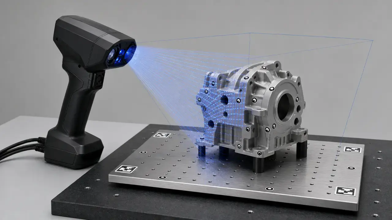
The best 3d scanner for 3d printing is the one that fits the part, the tolerance target, and the amount of post-processing you can accept. There is no universal best scanner, only better fits for specific scan-to-print workflows. NIST’s structured-light guidance is a useful reminder that single-view and multi-view measurement situations are not identical, so one advertised millimeter number rarely tells the whole story. [5] A general-purpose structured-light example such as Artec Eva shows the kind of output a maker workflow may need, with STL, OBJ, and PLY export plus accuracy up to 0.1 mm. [5] [6]
Printer behavior still matters after scanning, because the printed result reflects process limits as well as scanner quality. Formlabs’ Form 4 Design Guide gives a model-specific tolerance example of ±0.15% for 1–30 mm features with a ±0.02 mm lower limit, which is why scanner specs and printer specs need to be read together rather than in isolation. [13] If the job is reverse engineering, the workflow often continues into cleanup, hole filling, decimation, alignment, feature extraction, cross-sections, and STEP, IGES, or DXF export rather than ending at the mesh. [16]
Choose by:
- object size
- tolerance
- surface material
- workflow
- export path
Why this question exists now: from metrology to maker workflows
3D scanning is no longer limited to metrology labs and reverse-engineering departments. It now shows up in workshops, classrooms, prototyping rooms, and hobby spaces. That makes terminology more important, not less. ASTM E2544-24 exists to standardize 3D imaging language, which matters when people compare scanners across inspection, modeling, and print-preparation use cases. [1] At the same time, ISO/ASTM 52900:2021 defines additive manufacturing as building physical 3D geometries by successive addition of material, a useful reminder that scanning and printing solve different problems even when they are used together. [3]
That shift turned the scanner for 3d printer question into a workflow question rather than a one-device question. A part may be captured for inspection, remade in CAD, cleaned into a mesh, or exported for printing. NIST notes that VDI/VDE 2634 Part 2 applies to single-view area scans, while Part 3 applies to multiple-view workflows that extend the measurement volume. [5] The practical issue is not whether one scanner is universally “best,” but whether the device matches the capture method, the object, and the downstream steps.
What a 3D scanner does vs what a 3D printer does
A 3D scanner and a 3D printer do opposite jobs. The scanner captures geometry by measuring an existing object, while additive manufacturing creates a new object by successive addition of material. [3] ASTM E2544-24 matters here because 3D imaging terms are easy to blur together, especially when people treat models, meshes, scans, and measurements as interchangeable. [1]
That is why a captured surface is not automatically a finished replacement part. A scan records what exists now, including wear, dents, shrinkage from prior processing, or deformation, while a printed part is constrained by the printer, the material, and the print process itself. Formlabs’ Form 4 guidance shows model-specific dimensional bands rather than a universal tolerance, so even a good scan still has to pass through the printer’s own limits before it becomes a usable object. [13]
How 3D scanners capture geometry
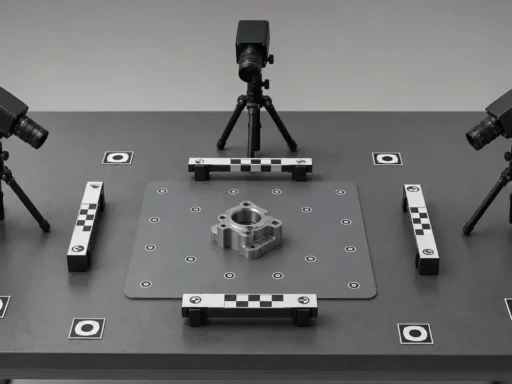
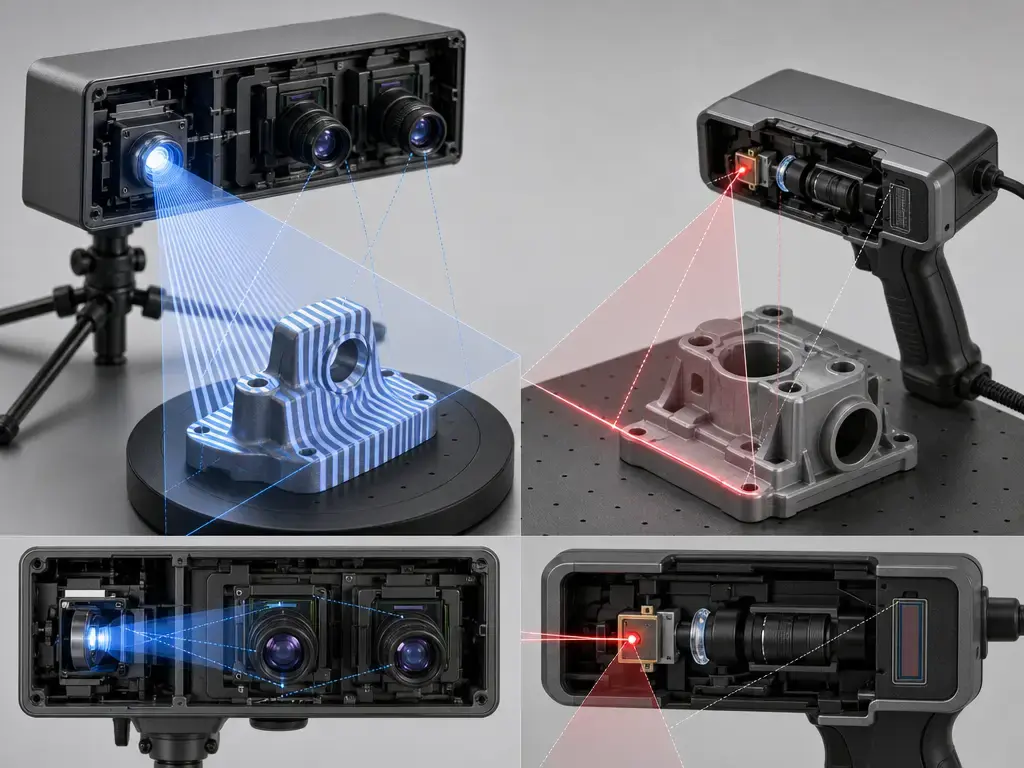
3D scanners measure shape by comparing how a sensor sees a surface from one or more known positions. In many systems, depth is estimated through triangulation: a projector or camera pair observes how a line or pattern shifts on the object, then software reconstructs 3D coordinates from that shift and the known geometry between projector, camera, and object. NIST describes this triangulation principle for structured-light scanners directly. [5] ASTM E2544-24 is relevant because the same label can imply different things in measurement, inspection, and modeling contexts. [1]
A structured light 3d scanner for 3d printing projects a pattern and reads its deformation from one or more cameras, which is why it is often a good fit for medium objects and controlled surfaces. Laser line scanners do something similar with projected lines rather than area patterns and are often better suited to handheld metrology workflows where volumetric accuracy and traceability matter. Photogrammetry reconstructs shape from many photographs, so its strength is broad visual coverage rather than direct dimensional certainty. For universal print-grade limits, no reliable figure found. Phone depth or LiDAR sensors are useful for quick captures and scene reference, but results still depend heavily on device hardware, subject distance, lighting, and the amount of cleanup your workflow can tolerate. NIST’s structured-light analysis is a reminder that single-view and multi-view conditions are not equivalent, so no universal single accuracy figure can describe every capture. [5]
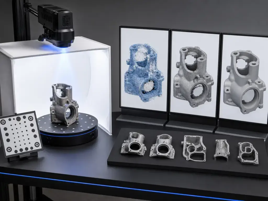
A scan usually becomes one of several output types. A point cloud is a set of measured surface points. A polygon mesh is a connected surface approximation built from those points. A textured mesh adds image or color information. CAD or BRep geometry is a later reconstruction step built from explicit faces, edges, and features rather than raw captured triangles. ASTM E2807 describes the E57 format as a way to store 3D point data, related attributes such as color or intensity, and 2D imagery in SI units. [2] That makes E57 useful for scan exchange and archiving, but it is not the same thing as a finished CAD model or a slicer-ready print file. [16]
Common scanner outputs:
- point cloud
- polygon mesh
- textured mesh
- CAD entities after reverse engineering
- print-ready export such as STL, OBJ, or 3MF
Scan-to-print workflow: from object to printable mesh
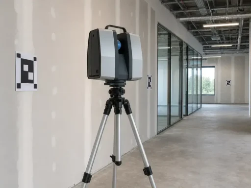
A good scan-to-print workflow usually succeeds or fails before the first frame is captured. Clean the object, decide whether markers are needed, calibrate the scanner if the device requires it, and control the lighting so the sensor sees stable surface information instead of glare or moving shadows. A turntable can simplify small-part work because it reduces repositioning and makes alignment more predictable. Matte spray can sometimes help on glossy or transparent surfaces, but it is a caveated aid rather than a blanket recommendation, especially for valuable, sensitive, or safety-critical objects. The goal is to reduce tracking loss and bad data early, because every avoidable capture problem becomes mesh cleanup later. [5] [16]
- Prep the object and scene.
- Calibrate the scanner if required.
- Capture overlapping views from enough angles to cover the part.
- Align or register the scans.
- Fuse or mesh the capture data.
- Repair the model and run a watertight check.
- Export, slice, and test print.
The format decision comes after that process, not before it. E57 is a point-cloud exchange standard that can store point data, attributes, imagery, and SI-based quantities. [2] STL is still common for simple mesh handoff, but it does not carry units or richer manufacturing context by itself. 3MF is an XML + ZIP container recognized as ISO/IEC 25422:2025, and the consortium lists 9 published extensions on its site, which is why it can preserve more print-relevant information where the software chain supports it. [15] CAD exports such as STEP or IGES are for remodeling and engineering handoff, not raw scan capture. [16]
| Format | Data type / best use | Keeps units/metadata? | Typical downstream tool |
|---|---|---|---|
| STL | Triangle mesh for simple print handoff | Usually no | Slicer |
| OBJ | Mesh, often with texture/color workflows | Limited by workflow | Modeling or slicer |
| PLY | Mesh or point-cloud exchange | Some attributes, not full print intent | Scan or modeling software |
| E57 | Point-cloud and image exchange | Yes, SI-based quantities | Scan processing or metrology |
| 3MF | Print-oriented package | Yes, where supported | Modern slicer or print prep |
| STEP | CAD geometry exchange | Yes | CAD |
| IGES | Legacy CAD surface/curve exchange | Yes | CAD |
Capture quality depends on overlap, coverage, and stable tracking. Multiple angles reduce occlusion, but they do not eliminate it, so hidden regions, deep pockets, and undercuts may still need a second pass or a different setup. After registration, look for doubled surfaces, holes, spikes, and misaligned seams before export. Post-processing then turns raw geometry into something usable through fusion, meshing, hole filling, smoothing, decimation, scaling, and validation. Blender’s 3D Print Toolbox notes that a mesh should be watertight for slicing, and that non-manifold edges are edges not connected to exactly two faces. [14] Creaform’s scan-to-CAD workflow description likewise lists mesh cleanup, hole filling, mesh merging, decimation, watertight preparation, alignment, feature extraction, cross-sections, and CAD export as separate steps. [16] That is why a scan is the start of a manufacturing workflow, not the end of it.
When mesh-only is enough — and when CAD remodeling is required
A mesh-only workflow is enough when the goal is visual reproduction rather than functional redesign. That covers props, statues, decorative covers, ergonomic grips, cosplay parts, and other organic or low-risk forms where the scanned surface is the deliverable. In that kind of job, broad export support and realistic size limits matter more than a promise of perfect editability. Revopoint’s MetroX product page, for example, lists output formats including PLY, OBJ, STL, ASC, 3MF, GLTF, and FBX, along with a minimum scan volume of 10 × 10 × 10 mm and a maximum scan volume of 1 × 1 × 1 m. [11] But even here, the scan captures the as-built surface, not automatically the original design intent.
CAD remodeling is required when the part has holes, threads, bosses, mating faces, datums, brackets, or tolerances that must be edited and controlled explicitly. That is the typical 3d scanner for reverse engineering case, where scan-to-CAD work usually includes alignment, feature extraction, cross-sections, surface creation, and export to STEP, IGES, or DXF. [16] It also matters because printer-side behavior still limits the result after scanning. Formlabs’ Form 4 guide gives different dimensional bands for 1–30 mm, 31–80 mm, and 81–150 mm features rather than one universal number. [13] If the part has to fit, mate, seal, or assemble, remodeling the scan into clean CAD is often the real job.
-
Mesh-only use cases:
-
props and statues
-
decorative covers and housings
-
organic shapes where the surface itself is the goal
-
CAD-required use cases:
-
functional parts with holes, bosses, and mating faces
-
tolerance-driven repairs and replacements
-
editable engineering models where design intent must be recovered
Types of 3D scanners for 3D printing
Structured light
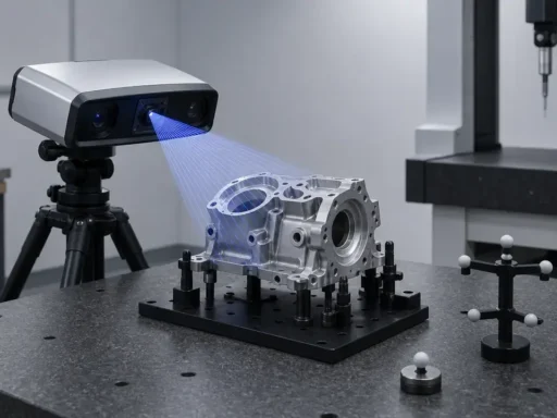
A structured light 3d scanner for 3d printing is often the most familiar class for medium objects, props, and general surface capture. Artec Eva is a representative example: its current product page lists a 0.4–1 m working distance, accuracy up to 0.1 mm, 3D resolution up to 0.2 mm, accuracy over distance up to 0.1 mm + 0.3 mm/m, a 3D reconstruction rate up to 16 FPS, and output including STL, OBJ, and PLY. [6] The catch is that optical area scanning remains sensitive to reflectivity, field of view, tracking quality, and part position within the measurement volume. NIST explicitly notes that a single accuracy figure may not be adequate because performance varies with location and distance. [5]
Blue laser and handheld metrology scanners
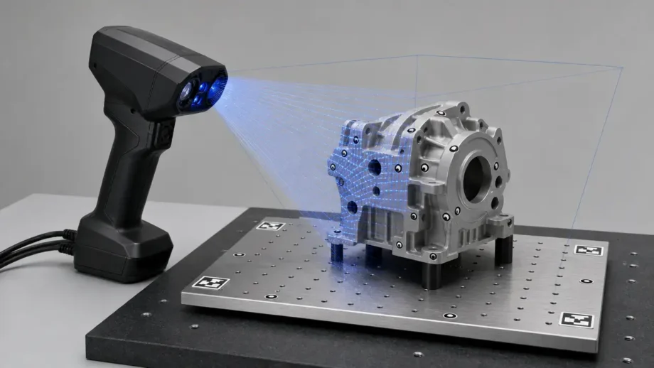
Blue laser and hybrid handheld systems are a better fit when the target is a mechanical part, a scanner for 3d printing in an inspection-oriented workflow, or a surface that is dark, reflective, or otherwise awkward for simpler capture methods. Creaform’s HandySCAN 3D BLACK Series technical-specifications page lists 0.025 mm accuracy, 0.020 mm + 0.040 mm/m volumetric accuracy, 0.025 mm measurement resolution, and 1,300,000 measurements per second for the HandySCAN BLACK Elite, with performance tests done in ISO/IEC 17025 accredited calibration laboratories and acceptance testing based on VDI/VDE 2634 Part 3. [8] [9] Shining 3D’s FreeScan Combo Series adds a hybrid example with 0.02 mm accuracy, 0.02 + 0.033 mm/m volumetric accuracy, point distance ranges of 0.05–10 mm and 0.1–3 mm depending on mode, scan speeds up to 3,600,000 points/s, a 620 g body, and published lab conditions of 20 ± 0.5 °C and 40–60% RH. [10] Those details are useful, but only if read as measured conditions rather than universal truths.
Desktop turntable scanners
Desktop turntable scanners are usually the easiest class for small parts because the object stays centered and the alignment burden is lower than in fully handheld capture. They are often practical for miniatures, figurines, jewelry-like parts, and small enclosures, but this is a workflow advantage, not a universal precision class. NIST’s cautions still apply: performance changes with setup, object position, and how results are stitched or filtered, and the VDI/VDE guidance does not provide a catch-all resolution threshold that tells you the smallest printable feature in every situation. [5] No reliable figure found supports a single universal benchmark for this whole category, so detailed specs should be checked model by model.
Photogrammetry and phone LiDAR/depth
Photogrammetry and phone LiDAR or depth sensors are convenience-first capture methods, not first-choice metrology tools. They can be useful for broad shape reference, rough inspection, scene capture, or texture-driven work, but their limitations show up quickly when the task becomes fit-critical, reflective, deeply occluded, or dimensionally strict. NIST’s warning about position-dependent and distance-dependent accuracy applies here as well: no reliable figure found supports treating phone depth capture or casual photogrammetry as a universal answer for print-ready parts. [5] The practical question is usually whether the workflow can tolerate more cleanup and manual remodeling, not whether the first capture felt easy.
Performance metrics that matter more than marketing
Spec sheets mix several different ideas, and they do not all describe the same thing. Accuracy is closeness to the true value. Precision or repeatability is how tightly repeated measurements agree. Resolution or point distance describes spacing or density, not guaranteed feature detectability. Volumetric accuracy describes how error behaves over a scan length or volume. Working distance and field of view affect what part of an object can be seen at once, while scan speed and tracking affect how efficiently coverage can be maintained without losing alignment. VDI/VDE 2634 Part 2 is a core reference for area-scanning performance language, and NIST points out that the guidelines do not recommend tests to determine scanner resolution in the X, Y, and Z axes as a universal minimum-feature metric. [4] [5]
| Metric | What it means | Why it matters for 3D printing | Watch out for |
|---|---|---|---|
| Accuracy | Closeness to true dimension | Fit and reverse engineering | “Up to” lab values |
| Resolution / point distance | Spacing of captured detail | Small features and relief | Not the same as accuracy |
| Volumetric accuracy | Error over object length or volume | Larger parts and stitched scans | Alignment drift and setup effects |
| Output format | STL, OBJ, PLY, 3MF, STEP, IGES, E57 | Slicer/CAD compatibility | Mesh is not CAD |
Manufacturer examples make the distinction concrete. HandySCAN BLACK Elite separates 0.025 mm accuracy from 0.020 mm + 0.040 mm/m volumetric accuracy. [8] Revopoint MetroX separates single-frame precision up to 0.01 mm, single-frame accuracy up to 0.02 mm, volumetric accuracy of 0.025 mm + 0.05 mm × L (m), and fused point distance up to 0.05 mm, with L defined as object length. [11] Shining 3D’s FreeScan Combo Series publishes 0.05–10 mm and 0.1–3 mm point distance ranges together with controlled environmental conditions of 20 ± 0.5 °C and 40–60% RH. [10] NIST adds the critical caveat: accuracy varies based on artifact location and distance from the scanner, so a single accuracy value may not be adequate for the end user. [5]
Scanner-side numbers also need to be matched to printer-side behavior. Formlabs’ Form 4 guide gives 1–30 mm features at ±0.15% with a ±0.02 mm floor, 31–80 mm features at ±0.2% with a ±0.06 mm floor, and 81–150 mm features at ±0.3% with a ±0.15 mm floor. [13] Those are model-specific printer figures, not a universal SLA rule. If the model still needs heavy mesh cleanup, smoothing, or scale correction after capture, the effective dimensional fidelity of the workflow can drift further from the scanner’s headline number.
Do not compare these as if they are the same:
- single-frame accuracy
- volumetric accuracy
- precision/repeatability
- point distance / mesh density
- printer tolerance
Best scanner class by use case
Best for organic models and props
For organic models, costume parts, and props, the main goal is usually coverage and cleanup tolerance rather than metrology-grade traceability. A class such as structured light, and sometimes photogrammetry when dimensional strictness is lower, makes more sense than chasing the smallest published error number. Formlabs frames the buying decision as a workflow match rather than a single-spec contest. [12] If the final print only needs visual continuity, alignment stability and a watertight export can matter more than metrology language on the brochure. [14] [15]
Best for mechanical reverse engineering
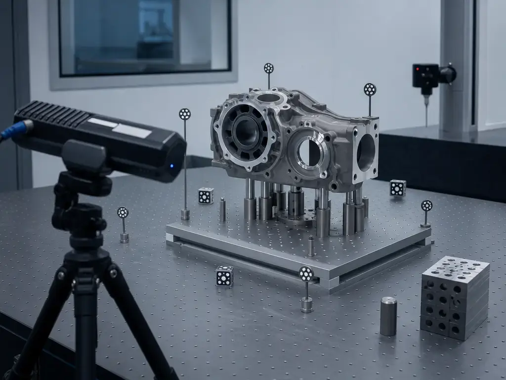
For mechanical reverse engineering, prioritize scanners that publish volumetric accuracy clearly, support markers or other robust tracking, and fit into a scan-to-CAD workflow. HandySCAN BLACK Elite is a useful reference point because it separates 0.025 mm accuracy from 0.020 mm + 0.040 mm/m volumetric accuracy and ties testing to VDI/VDE 2634 Part 3 and ISO/IEC 17025 lab work. [8] [9] Revopoint MetroX and Shining 3D FreeScan Combo Series are also useful comparison points because they distinguish single-frame accuracy, volumetric accuracy, point distance, and tracking modes instead of collapsing everything into one number. [10] [11] Reverse engineering then continues beyond scanning into alignment, feature extraction, cross-sections, and export to STEP, IGES, or DXF. [16]
Best for small detailed objects
For jewelry, miniatures, and other small detailed objects, close-range detail and stable positioning matter more than raw scan speed. Artec Spider II is a representative example of that class: the current specs page lists accuracy up to 0.05 mm, resolution up to 0.05 mm, a 0.19–0.3 m working distance, and a 1,800 cm³ capture zone. [7] In practice, a desktop or turntable-centered workflow is often easier here because it helps keep the part still and the scan path predictable, but the benefit still depends on lighting, surface finish, and how much cleanup you can accept afterward.
Best for automotive trim and medium parts
Automotive trim, housings, and other medium parts usually need a balance of field of view, working distance, and robust tracking rather than only the finest point spacing. Artec Eva’s 0.4–1 m working distance and Artec Spider II’s closer 0.19–0.3 m range illustrate why scanner choice changes with part size. [6] [7] Shining 3D’s FreeScan Combo Series is another example of a handheld class built for wider coverage, with published accuracy of 0.02 mm, volumetric accuracy of 0.02 + 0.033 mm/m, and a 620 g scanner body. [10] This category is less about chasing the smallest feature on paper and more about keeping geometry stable over a wider part.
Best for checking printed parts
A metrology-oriented scanner can be useful for checking printed parts, but it should be treated as a validation tool, not a shortcut around process limits. A scanner for 3d printer quality checks makes the most sense when comparison data will affect design decisions, acceptance, or process control. Formlabs’ Form 4 guide is a good reminder that printed dimensions remain model- and size-dependent even before you start comparing scan data. [13] If you are using scanned comparison as QA evidence, published traceability language such as VDI/VDE 2634 Part 3 acceptance testing or ISO/IEC 17025 lab context matters more than hobby-level convenience. [8] [9] Before any comparison, make sure the model is at least watertight and free of obvious non-manifold failures. [14]
Limitations and failure modes
Shiny, transparent, black, or very dark surfaces are common failure cases for optical scanning because they reduce usable image information or confuse the system’s view of the projected pattern. Fine hair, soft fabric, thin edges, and deep pockets can also produce partial or noisy captures. NIST notes that measurement quality changes with geometry, target position, and distance from the scanner, so these failures are not just bad luck. [5]
Geometry can fail even when the surface is scan-friendly. Occlusion creates holes behind lips, undercuts, and internal cavities. Featureless regions give tracking too little information. Repeated patterns can mislead alignment. Moving or flexing targets break frame-to-frame consistency. In multi-view workflows, some error accumulates through capture and alignment, which is exactly why NIST distinguishes single-view from multiple-view evaluation. [5] For sensitive heritage, medical, or safety-critical objects, surface treatment should not be treated as a default recommendation. A different capture mode, a different scanner class, or plain manual measurement may be the better choice.
Workflow errors can be just as damaging as capture errors. Oversmoothing can erase fit-critical detail. Scale mistakes propagate into the print. A non-manifold mesh is not print-ready, and Blender defines non-manifold edges as edges not connected to exactly two faces. [14] “Up to” specs can also create false confidence when the real setup is far from the conditions used for the published result.
- when spray may help: glossy or transparent surfaces, with object-safety caveats
- when targets or markers help: featureless parts or longer multi-view scans
- when a different scanner mode is better: deep pockets, reflective trim, or changing working distance
- when scanning is the wrong tool: simple prismatic parts, internal geometry, or parts faster to model directly
Bottom line: the best 3D scanner for 3D printing depends on the workflow
The best 3d scanner for 3d printing depends on the part, the tolerance target, the surface, and the work you are willing to do after capture. NIST’s guidance is the key filter here: a single number is not enough, because performance changes with distance, artifact position, and whether the result comes from one view or many aligned views. [5] Read scanner specs together with printer behavior, because the same scan can lead to different print results on different machines, materials, and feature sizes. [13]
When not to buy a scanner:
- simple prismatic parts
- holes and threads that can be modeled directly
- parts faster to measure with calipers
- jobs where CAD from scratch is quicker than scan cleanup
For many functional parts, scan-to-CAD work adds alignment, repair, feature extraction, and export steps that may outweigh the value of scanning in the first place. [16] If the object is too reflective, too small, too occluded, or already well-defined in CAD, direct modeling may be the faster and more reliable route. [5] [16]
FAQ
The quick answers below keep the workflow-first point intact: there is no universal best scanner, only better fits for specific scan, mesh, CAD, and print chains. [5]
What is the best 3D scanner for 3D printing?
The best 3D scanner for 3D printing is the one that fits the part size, detail level, and downstream workflow. For small detailed parts, a close-range high-detail scanner can be the better fit; for medium parts and props, a general-purpose structured-light class often makes more sense; for mechanical reverse engineering, volumetric accuracy and scan-to-CAD matter more. [5] [16]
Do I need a scanner for 3D printer projects?
Not always. If the part is simple, calipers and CAD may be faster and more controllable. A scanner helps most when geometry is organic, worn, awkward to measure, or hard to model from scratch. [12] [16]
Is a structured light 3D scanner good for 3D printing?
Yes, often. A structured light 3D scanner can be a strong choice for medium objects and scan-to-print work, but setup, surface properties, and multi-view behavior still affect the result. NIST specifically warns against treating one advertised accuracy figure as universal. [5] [6]
Can I use a 3D scanner for reverse engineering and 3D printing?
Yes, but reverse engineering usually means remodeling the scan in CAD rather than simply exporting an STL. Typical scan-to-CAD work includes cleanup, alignment, feature extraction, cross-sections, and export to STEP, IGES, or DXF. [16]
What file format should I export from a scanner for 3D printing?
For mesh printing, export a watertight model in a slicer-friendly format and verify that the mesh has no obvious non-manifold problems. Blender’s 3D Print Toolbox is a common way to check readiness. If your workflow supports it, 3MF is usually richer than STL because it is an XML + ZIP container that can preserve more metadata and print context. [14] [15]
Expert-level: How do single-frame accuracy and volumetric accuracy differ?
They answer different questions. Single-frame accuracy describes one capture condition, while volumetric accuracy describes how error behaves across object length or stitched measurement volume. MetroX, for example, separates single-frame accuracy up to 0.02 mm from volumetric accuracy of 0.025 mm + 0.05 mm × L (m), where L is object length. [11] [5]
Expert-level: When is CAD remodeling mandatory after scanning?
CAD remodeling becomes mandatory when the mesh is only reference geometry, not the final manufacturable model. That is common for parts with holes, threads, mating faces, datums, brackets, or tolerances that must be dimensioned explicitly. Printer behavior still limits the final result after scanning, so the mesh alone is rarely enough for functional engineering work. [16] [13]
Sources
Citations in the article body use numbered source IDs in the form [1].
- ASTM E2544-24, Standard Terminology for Three-Dimensional (3D) Imaging Systems
- ASTM E2807-11, Standard Specification for 3D Imaging Data Exchange, Version 1.0
- ISO/ASTM 52900:2021, Additive manufacturing — General principles — Fundamentals and vocabulary
- VDI/VDE 2634 Part 2, Optical 3-D measuring systems based on area scanning
- NIST, Sources of Errors in Structured Light 3D Scanners
- Artec Eva official specifications
- Artec Spider II official specifications
- Creaform HandySCAN 3D BLACK Series technical specifications
- Creaform HandySCAN BLACK Series brochure
- Shining 3D FreeScan Combo Series official specifications
- Revopoint MetroX Series official specifications
- Formlabs, How to Choose the Best 3D Scanner to Use With Your 3D Printer
- Formlabs Form 4 Design Guide
- Blender Manual, 3D Print Toolbox
- 3MF Consortium, The File Format for 3D Printing
- Creaform Scan-to-CAD Software Module