
Summary
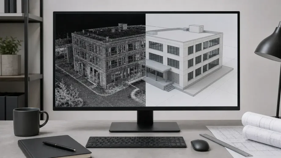
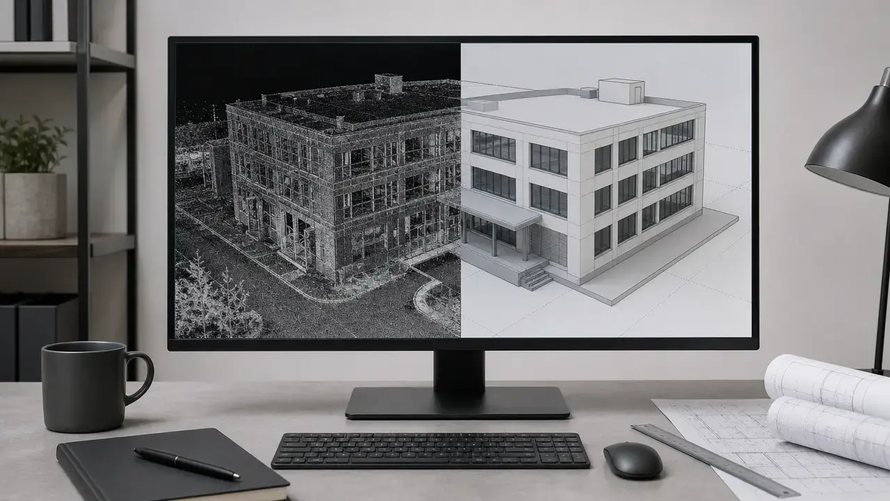
A point cloud to revit workflow starts with linking indexed scan data into Revit as a reference, then building the as-built model around that reference. Revit accepts .rcp and .rcs point-cloud files, and because point clouds can run from hundreds of millions to billions of points, they stay linked rather than becoming editable Revit geometry. [1] [2]
That distinction matters in scan-to-BIM work. A linked cloud can be positioned, viewed, snapped to, and checked, but it does not automate the creation of trustworthy walls, floors, MEP systems, or families. The main risks usually sit upstream and downstream of the link itself: complete handoff of support files, correct coordinate strategy, disciplined modeling scope, and auditable QA against what the scan actually shows. This article focuses on that production chain so intermediate Revit users can move from scan delivery to a controlled as-built model without treating “import” as automatic BIM creation. [1] [2]
Point cloud to Revit workflow
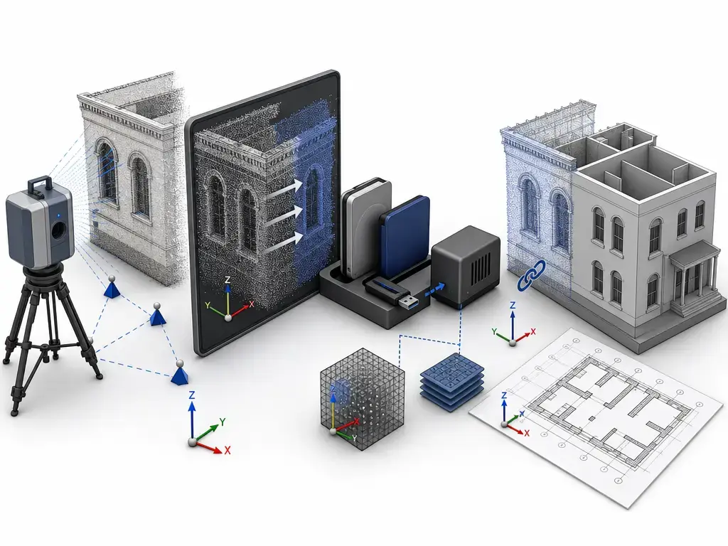
In practice, the point cloud to revit workflow is a handoff chain, not a single command in Revit. Scan data is captured and registered, reviewed for completeness, converted or indexed into a deliverable Revit can use, positioned in the project with the correct coordinate basis, then modeled to the agreed scope and checked against the cloud before issue. In many pipelines, ReCap sits between scanner-native data and Revit because it supports imports such as E57 and exports including RCP/RCS. Autodesk also notes that structured E57 export is a complete export of all data, so project deletions or clips are not carried through as a filtered deliverable. [8] [19] [20]
Revit is the consumption and modeling environment, not the stage where the cloud becomes editable BIM geometry. “Importing point cloud into Revit” is therefore a linking-and-modeling process: the cloud is brought in as a reference, then levels, grids, and model elements are created around it. If the upstream handoff is weak, the downstream model inherits those problems. If the handoff is controlled, the cloud becomes a reliable reference for an as-built deliverable instead of a large file nobody fully trusts. [1] [2]
A workable production sequence usually looks like this:
- Define deliverables and LOA/LOD expectations before modeling starts, so scope and verification are agreed early. [13] [14]
- Plan capture for coverage and occlusions based on what must actually be modeled, not just what is easy to scan.
- Register scans and review the registration outputs for fit quality, visual coherence, and obvious drift before anyone opens Revit.
- Confirm coordinate basis and units so the delivery is clearly local, surveyed, or already prepared for shared coordinates.
- Export or index the working deliverable to RCP/RCS after upstream interchange and archive decisions are made. [1] [8] [19]
- Link the cloud into Revit as a reference object rather than expecting editable geometry. [1] [2]
- Choose the positioning method and coordinate strategy that matches the project, not the default that happens to place something on screen. [1] [6]
- Set levels and grids from evidence so the model framework reflects measured conditions.
- Model elements only to the agreed scope and only where the cloud supports them.
- Run model-to-cloud QA and issue the deliverable package with assumptions, exclusions, and supporting files intact. [9] [13]
What to verify before you ever open Revit
Before Revit sees the cloud, verify whether the scan set is complete and internally credible. Coverage has to match the modeling scope, and occlusions need to be called out instead of discovered halfway through production. Review the scan-to-scan fit summary or residual report for consistency, then inspect the cloud visually for duplicate surfaces, drifting edges, tilted geometry that should be plumb or level, and planes that refuse to align cleanly across scan positions. If control was used, check for gross offsets or rotation errors against the intended basis. NIST’s review of automated as-built BIM creation is a useful reminder that this is not a simple import problem: geometric modeling, object recognition, and object relationship modeling are separate tasks, which is why weak input data becomes rework later. [12]
The file package matters just as much as the geometry. An RCP does not carry the scan data by itself; it references the RCS files that must remain available. Autodesk also recommends local point-cloud storage with a consistent relative root path in worksharing setups, so the same linked cloud resolves correctly across machines. Confirm units and coordinate basis at handoff, because a cloud that is locally correct but mislabeled as surveyed data can be placed just as badly as a poorly registered one. [7] [9]
Use a pre-import checklist before anyone starts modeling:
- File set completeness — confirm the RCP, referenced RCS files, and any companion exports are all present. [9]
- Coordinate basis — confirm whether the delivery is local, survey-based, or already prepared for shared coordinates.
- Units — verify the handoff units before placement or measurement checks.
- Extents — confirm the cloud is not going to land far outside the intended working area.
- Registration report availability — keep the residual or fit summary with the delivery package.
- Control alignment status — if survey control was used, confirm there are no gross offsets or tilt issues.
- Coverage and occlusions — note incomplete rooms, façades, ceiling voids, plant zones, and blocked areas.
- Revit version and project environment — confirm the target Revit setup before linking.
- Intended categories to model — define what becomes BIM and what stays reference-only.
- Storage location — keep the cloud in a stable local folder structure that matches the expected root path. [7]
File formats and deliverables
For most teams, the handoff decision is straightforward: Revit’s point-cloud linking UI is RCP/RCS, while E57 is usually handled upstream in ReCap or scanner software. In Revit, an RCP project can aggregate multiple RCS scan files. ReCap supports imports such as E57 and exports including E57, PTS, and RCP/RCS, and its E57 import documentation shows support for E57 point data with optional associated imagery when present. ASTM’s E57 listing describes the format as a container for 3D point data, associated attributes such as color or intensity, and 2D imagery, with standardized quantities in SI units and planar angles in radians. [1] [8] [10] [19]
The support-folder reality is what usually breaks handoff. Autodesk states that an RCP is a relatively small project file that references scan data and does not contain it, so sending only the RCP is not enough if the receiving team does not also get the RCS files. For archive or neutral exchange, E57 is often useful upstream; for day-to-day linking and modeling inside Revit, RCP/RCS is the practical working pair. [8] [9] [20]
| Format | Best use | Revit/ReCap role | Main caveat |
|---|---|---|---|
| RCP | Project handoff and grouped scan references. | Small project file that references one or more RCS files for Revit linking. [1] [9] | Sending only the RCP is insufficient if the referenced RCS files are missing. [9] |
| RCS | Indexed scan data for working links. | The actual indexed scan data used directly in Revit or through an RCP grouping file. [1] [9] | The expected folder structure and path relationship must remain valid. [7] [9] |
| E57 | Upstream interchange or archive. | Commonly imported or exported in ReCap before conversion to a Revit working delivery. [8] [10] [19] | It is not the native Revit linking format, and ReCap’s structured E57 export is a complete export that does not apply project deletions or clips. [1] [8] [20] |
Importing point cloud into Revit: coordinates and placement
Revit offers four positioning choices for point clouds: Auto – Center to Center, Auto – Origin to Origin, Auto – By Shared Coordinates, and Auto – Origin to Last Placed. None is universally best. Center to Center is useful for quick local alignment checks, Origin to Origin works when the incoming cloud origin already matches the model’s intended reference, By Shared Coordinates is the controlled option for multi-file or georeferenced work, and Origin to Last Placed helps place additional clouds consistently after the first one is aligned. [1]
The decision has to match the project’s coordinate logic. Autodesk warns that using Origin to Origin for a point cloud stored in a geographical or surveyor coordinate system is likely to place it very far from the rest of the model. Revit also notes that, by default, the project origin and shared origin begin in the same location, so Origin to Origin and By Shared Coordinates can initially appear to do the same thing until shared coordinates are actually established. For coordinated projects, shared coordinates should be created deliberately with Acquire Coordinates or Publish Coordinates, and Autodesk advises deriving shared coordinates from one file. Keep the internal origin constraint in mind as well: all geometry should stay within 10 miles (16 km) of the internal origin, and the modeling work plane is 20 miles (32 km) in diameter. Beyond that range, graphics and placement become less reliable. [1] [4] [5] [6]
Local-building workflow vs surveyed/georeferenced workflow (what to do in Revit)
| Goal | Preferred strategy | Revit positioning option(s) | Failure mode to avoid |
|---|---|---|---|
| Local-building workflow near the internal origin | Keep the cloud and model near the working area, then align intentionally and model from that local basis. | Auto – Center to Center or Auto – Origin to Origin, depending on whether the source origin is meaningful. [1] | Letting the cloud land far from the model and then “fixing” it by moving coordinate points at random. |
| Verified shared coordinates across multiple files | Establish shared coordinates first and keep one-file derivation discipline. | Auto – By Shared Coordinates after Acquire Coordinates or Publish Coordinates. [1] [6] | Assuming shared coordinates exist just because the first placement looks correct. |
| Survey-controlled model with large site offsets | Use a controlled georeferenced setup, verify extents early, and keep modeled geometry within Revit’s working limits. | Auto – By Shared Coordinates, with coordinate checks before modeling. [5] [6] | Pushing geometry beyond the 10 miles / 16 km limit from the internal origin, which can make graphics and placement unreliable. [5] |
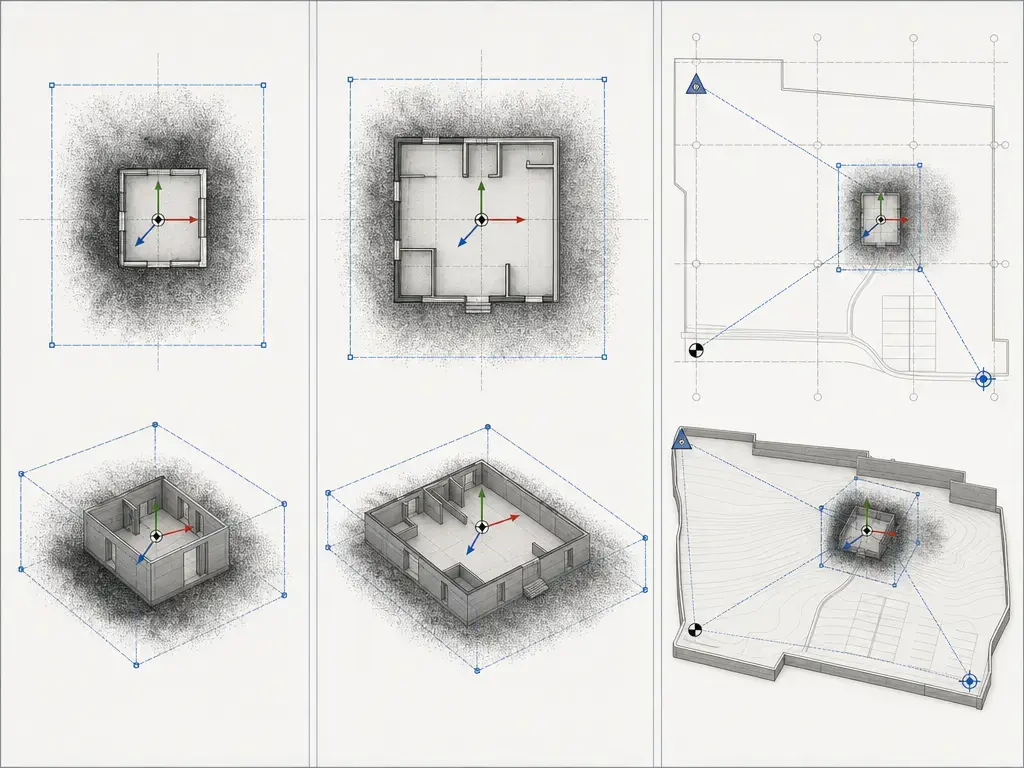
Coordinate guardrails: internal origin vs project base point vs survey point
Define these once and use them consistently. The internal origin is the fixed zero point of Revit’s internal coordinate system, and Autodesk states that its location never moves. The project base point is the local project reference typically used for project coordinates, while the survey point relates the model to real-world coordinates. Autodesk also explains an important difference in behavior: moving the survey point unclipped changes the internal origin in relation to the survey point and effectively moves the modeling work plane, while moving the project base point changes that point relative to the internal origin and leaves the work plane stationary. Do not try to fix a far-away cloud by randomly moving base points; use a controlled coordinate workflow, then re-check extents and placement instead. [4] [5]
Modeling from the Revit point cloud
Modeling from a Revit point cloud is interpretation, not conversion. Start with levels and grids, and only place them where the scan evidence supports them. Revit helps by allowing inferred planar snaps and direct snaps to points, but direct point snapping is low priority and the Tab key cycles through the available snap options. Those tools speed up placement; they do not decide what the building condition means. [2]
Once the reference framework is set, move to the major architectural and structural elements that define the building envelope and primary constraints. In practical terms, system families are built-in categories such as walls, floors, and roofs, while loadable families are inserted components such as a specific door, fixture, or equipment item. Model the large, governing elements first because they establish the reference conditions that later detail has to fit.
MEP systems and detailed families should come later and only to the agreed scope. Ducts, pipes, cable tray, hangers, fixtures, and equipment need enough visible evidence in the cloud to justify modeling them. If a zone is unobserved or heavily occluded, the defensible choices are to document an assumption, obtain supplemental measurement, or exclude that area from the deliverable. That link between capture completeness and modeling scope is what keeps an as-built model credible when the point cloud is the source reference but not a one-click replacement for BIM geometry.
Performance metrics, LOA/LOD, and QA
The main quality question in scan-to-BIM work is not whether the cloud exists, but how measurement quality propagates into the model. ISO 17123-9:2018 frames terrestrial laser scanner field procedures around precision and repeatability, which helps separate instrument behavior from later interpretation and deliverable acceptance. ASTM E2938 similarly treats medium-range laser-based 3D imaging systems as a measurement problem across at least part of the 2 to 150 m range, and it explicitly notes that real-world object and environmental factors affect range performance. [11] [16]
A practical QA chain separates four different issues:
- Scanner or instrument performance context — capture quality begins with the measurement system and the conditions it worked under. [11] [16]
- Registration quality — scan-to-scan alignment quality is its own metric and should be reviewed separately from modeling. [12]
- Coordinate control — local coordinates, shared coordinates, and origin limits determine whether the cloud sits in a usable reference frame. [4] [5] [6]
- Model-to-cloud verification — delivered Revit elements still have to be checked back against the cloud by category and intended use. [13] [14]
No universal scan-to-Revit tolerance applies to every project; tolerance must be specified by intended use, element category, and verification method. USIBD’s current public LOA page identifies Specification Version 3.1 and notes guidance on using standard deviation as a basis for tolerance and on selecting the correct LOA from required tolerances. That is why “the scanner was accurate” and “the model is acceptable” are not the same statement. [13]
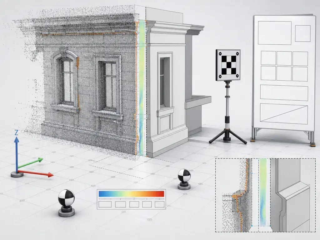
LOA vs LOD (and what each one means in this workflow)
In this workflow, LOA is the existing-conditions accuracy and verification framework used to describe how reliably scan-derived information represents observed conditions. LOD is about model development or detail intent in the deliverable. They answer different questions, and LOD is not measurement accuracy. A model can be highly developed in representation yet still be a poor geometric match to existing conditions if the capture, registration, coordinate setup, or QA process is weak. [13] [14]
Practical QA evidence
A model-to-cloud QA record should be auditable by someone who did not build the model. That means showing how the model was checked, where it was checked, what was excluded, and what assumptions were made. Registration residuals are useful metadata, but registration residual does not equal element tolerance compliance. USIBD’s LOA guidance points toward required tolerances and verification context, which is why the evidence trail matters as much as the final geometry. [12] [13]
- Sampled checks by category — representative walls, slabs, columns, gridlines, openings, and selected MEP runs.
- Issue-based review of uncertain zones — noisy areas, mixed surfaces, dense service spaces, and occluded regions.
- Documented assumptions and exclusions — what was inferred, simplified, deferred, or intentionally left out.
- Marked review views or sections — saved cut locations, comparison slices, or cloud review markers tied to modeled elements.
- Revision notes — what changed after each QA pass and why.
Troubleshooting: why is my point cloud not showing (or not where you expect)
When a cloud is missing in Revit, diagnose it in order: file integrity first, then view visibility, and only then coordinates. A broken reference can look like a visibility problem, and a visibility problem can look like a coordinate problem if you skip the basics. Autodesk’s point-cloud workflow is link-based, so missing support files and path mismatches are common failure points before any modeling issue is involved. [1] [7] [9]
Use this triage flow:
- File/link integrity — confirm the RCP can still resolve its referenced RCS files, and check whether the cloud was moved without its support folder. In worksharing, verify that each user’s local copy follows the expected root-path-relative structure. [7] [9]
- View visibility settings — make sure you are not in a drafting view or schedule view, then check the Point Clouds tab in Visibility/Graphics, the per-cloud or per-region visibility state, color mode, section box, crop region, and the relevant view range. [1] [3]
- Placement/coordinates problems — if the file resolves but nothing appears near the model, review the insertion method, the coordinate basis, and whether the geometry may have landed far from the internal origin. [1] [5]
The visibility branch is often simpler than it looks. Revit states that linked point clouds are visible in all views except drafting and schedule views. In plan or section, only the portion of the point cloud between the bottom extent and the cut plane is visible, so a cloud that shows in 3D can disappear in plan because of view range alone. The Visibility/Graphics dialog includes a Point Clouds tab for top-level clouds and child nodes such as scan locations and, when the cloud was created in ReCap, scan regions. Color mode also matters because RGB data with no source color can appear black, while other display modes include <No Override>, Single Color, Elevation, Intensity, and Normals. [1] [3]
If the problem is placement, revisit the coordinate logic instead of dragging the cloud around blindly. Autodesk warns that Origin to Origin on a geographically or survey-referenced point cloud can place it very far from the rest of the model, and Revit’s maximum-distance guidance still applies to linked geometry. Revit LT is a separate branch of this diagnosis: it can open a project containing point clouds and hide them in a view, but it cannot modify the point clouds. A practical sequence is: Did the file resolve? Can this view show it? Is it in the right place? [1] [5] [15]
Limitations and common failure modes
The largest limitation in scan-to-BIM work is incomplete observability. Occlusions hide geometry, clutter blocks critical surfaces, and reflective or very dark materials can produce sparse or noisy returns that make interpretation harder. Even when the scanner performs well, ASTM’s range-performance framing still applies: object geometry, texture, temperature, reflectance, vibrations, particulate matter, thermal gradients, ambient lighting, and wind can affect what the system measures. Those realities do not make the cloud useless, but they do limit what can be modeled confidently from it. [16]
Large datasets create a second class of problems, not because Revit cannot link them, but because users can misread views, extents, and display settings. Section boxes, cropped views, and carefully chosen working extents usually help more than repeated reloading or arbitrary repositioning. If mobile or SLAM-based capture is part of the workflow, treat it as a separate QA problem as well; error accumulation can distort larger structures, and loop closure is one of the standard ways SLAM systems address that risk. [2] [3] [17]
Adjacent workflows
Not every scan-derived workflow in Revit is a point-cloud workflow. Standard scan-to-BIM production uses linked point clouds as references for modeling, while mesh-based workflows convert or export data into surface-based representations for different purposes such as mesh review, visualization, or downstream mesh handling. Those are adjacent workflows, not interchangeable ones. [1] [18]
Callout — RCMR: ReCap Mesh Model linking uses its own ReCap Mesh command path in Revit and links .rcmr mesh files as external references. Treat it as an adjacent mesh workflow, not as the default substitute for Revit point-cloud linking with RCP/RCS. [18]
Applications
Scan-to-Revit workflows are useful when teams need an existing-conditions model rather than a design-only file. Typical applications include renovation and retrofit projects, tenant improvements, façade documentation, MEP coordination, heritage recording, verification against field conditions, facility-management baselines, and the starting model layer for a digital-twin program where later updates are compared against measured reality.
Brief context: why “import” is not “as-built BIM creation”
NIST’s review of automated as-built BIM reconstruction separates the problem into geometric modeling, object recognition, and object relationship modeling. That framing helps explain why a linked Revit point cloud does not, by itself, become a finished as-built BIM. The cloud is a dense measurement reference; the deliverable model still depends on interpretation, scope decisions, and QA. [12]
Practical takeaways
A reliable point cloud to revit workflow starts with clear scope, a validated scan package, and a deliberate coordinate strategy. From there, the cloud should be linked correctly, modeled only where the evidence supports it, and checked back against the source before issue. When planning, handoff, placement, modeling scope, and QA stay aligned, the Revit model is far more likely to remain defensible as an as-built deliverable.
FAQ
What is the best point cloud to Revit workflow for scan-to-BIM?
The best point cloud to Revit workflow is usually the most controlled one: define scope and verification needs first, confirm the scan package and coordinate basis, prepare RCP/RCS as the Revit working delivery, link deliberately, then model and QA only to the agreed scope. The “best” workflow is less about one button and more about avoiding rework in handoff, placement, and verification. [1] [8] [13]
How do I import (link) a point cloud into Revit, and what files does Revit accept?
Revit links indexed point clouds using .rcp and .rcs files. If your source data arrives as E57 or scanner-native data, it is typically handled upstream in ReCap or other capture software before the Revit link step. [1] [8]
RCP vs RCS: what’s the difference and what do I need to send to my Revit team?
RCP is the project-level reference file, while RCS is the indexed scan data it points to. In practice, send the whole support folder, not just the RCP, because Autodesk states that an RCP does not contain the scan data and depends on the RCS files being available. [1] [9]
Should I use Origin to Origin or Shared Coordinates for a georeferenced scan?
Use Origin to Origin only when you know the cloud origin already matches the model’s intended reference. For georeferenced work, Shared Coordinates is the controlled method after Acquire Coordinates or Publish Coordinates has been established. Also remember that Revit geometry should remain within 10 miles (16 km) of the internal origin, so a cloud placed on raw survey coordinates without a proper strategy can end up both far away and unreliable. [1] [5] [6]
Why is my point cloud not showing in a plan view, even though it appears in 3D?
Start with view rules before assuming the link is broken. In plan or section, the visible part of the cloud is the portion between the bottom extent and the cut plane, so view range can hide a valid cloud. Then check the Point Clouds tab in Visibility/Graphics, along with crop and section settings. [3]
Expert: How do you make model-to-cloud QA auditable without checking every point?
Use category-based sampling, issue-focused review zones, saved comparison sections, and explicit notes on assumptions and exclusions. The goal is to show how the model was verified and where uncertainty remains, not to imply that a registration report alone proves every element is within tolerance. Registration residual is supporting metadata, not a substitute for element-level verification. [12] [13]
Expert: How do LOA and LOD interact in an as-built Revit deliverable — and why isn’t LOD “accuracy”?
LOA and LOD complement each other but do not describe the same thing. LOA is the accuracy and verification framework for existing conditions, while LOD describes model development or representation intent. A highly developed model can still be a poor match to measured conditions if the capture, coordinates, or QA are weak, which is why LOD should never be treated as a measurement-accuracy label. [13] [14]
Sources
- Insert a Point Cloud File (Revit Help)
- About Point Clouds (Revit Help)
- Visibility/Graphics for Point Clouds (Revit Help)
- About the Internal Origin (Revit Help)
- About the Maximum Distance Limit (Revit Help)
- About Shared Coordinates (Revit Help)
- Options Dialog: File Locations Tab (Root path for point clouds) (Revit Help)
- Supported File Formats (ReCap Help)
- About Scan and Photogrammetry Files and Projects (Reality Capture / ReCap Help)
- ASTM E2807-11(2026) listing (E57 file format) (ASTM)
- ISO 17123-9:2018 listing (TLS field procedures; precision/repeatability) (ISO)
- NIST: Automatic Reconstruction of As-Built BIMs from Laser-Scanned Point Clouds (NIST)
- USIBD: Level of Accuracy (LOA) page
- USIBD BIM Series PDF (mentions LOA vs LOD framing)
- Revit LT: About Point Clouds and Revit LT (Revit Help)
- ASTM E2938 listing (relative-range performance; 2–150 m; environment factors) (ASTM)
- dynSLAM thesis (error accumulation; loop closure) (independent academic)
- Link a ReCap Mesh Model (RCMR) (Reality Capture Help)
- E57 Import Support — Technical Specification (ReCap Help)
- E57 Export Support — Technical Specification (ReCap Help)