
What Is a Pellet 3D Printer?
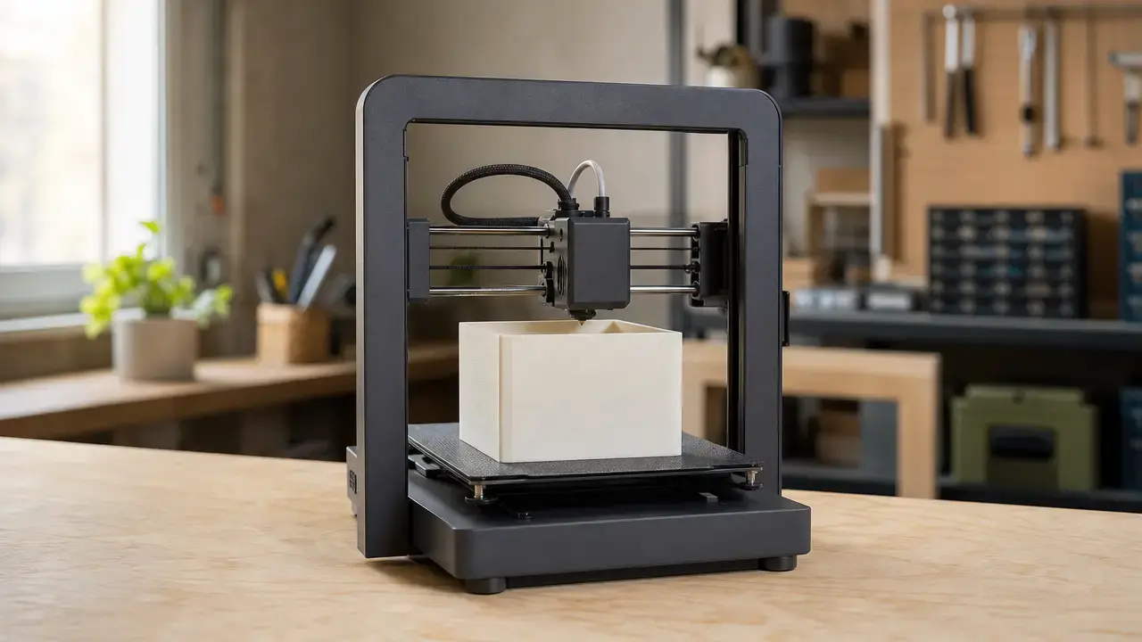
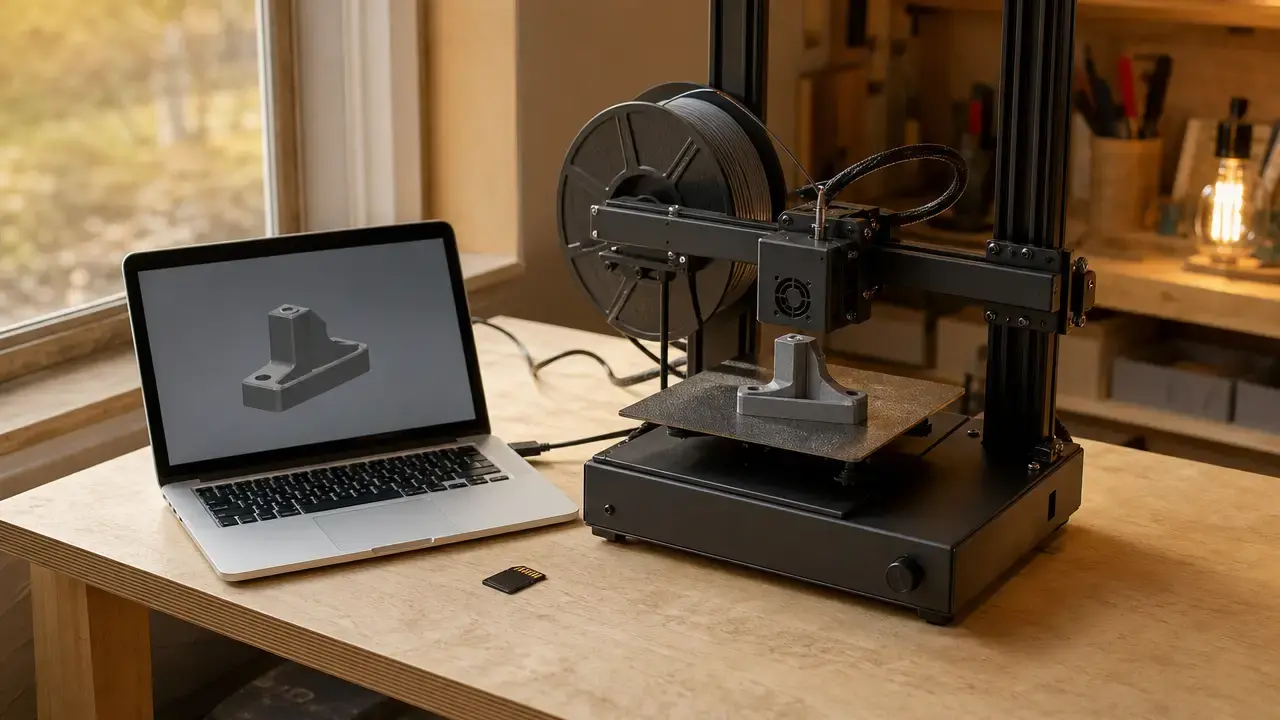
A pellet 3D printer is an additive-manufacturing machine that builds parts from 3D model data, usually layer by layer, using pellet-fed material extrusion (MEX) rather than continuous filament. In MEX, material is selectively dispensed through a nozzle or orifice; the feedstock may be polymer pellets, granules, or granulate. [1] Many pellet-fed MEX systems use a hopper-fed screw extruder, heated barrel zones, and a nozzle to convey, plasticize, pressurize, and deposit material. [3] [9] This arrangement can support high material throughput and larger parts, but it also places greater emphasis on drying, bulk handling, melt control, and validation. For the query “3d printer 3d model pellet,” the model and slicing workflow are conventional; “pellet” describes the feedstock and extruder architecture, not a special type of 3D model. [1]
Historical Background: Why Pellet-Fed MEX Exists
Polymer pellets are a standard upstream form for plastics processing. Filament is commonly made by converting pellets into a controlled-diameter strand for filament-fed systems. [2] Direct pellet feeding can remove that conversion step and broaden feedstock options, but it does not guarantee consistent extrusion, layer bonding, or compliance with a part requirement.
A systematic review identified 61 articles on screw-assisted additive manufacturing that printed directly from granulated materials. [3] The literature covers compact machines and larger systems designed for higher material delivery and wider deposited roads. Large-format additive manufacturing, or LFAM, is therefore often associated with pellet-fed equipment, but it is neither a synonym for pellet-fed MEX nor a description of every pellet-based machine. Direct pellet feeding changes the extrusion hardware, thermal history, and material-handling requirements; the digital workflow remains model preparation, slicing, and controlled layer deposition.
How a Pellet-Fed Material Extrusion Printer Works
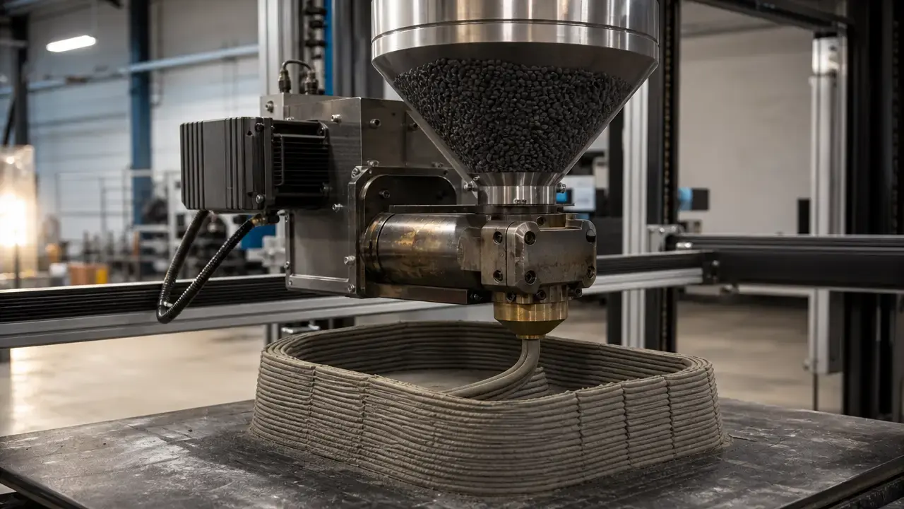
A typical material path begins with sealed storage and, where required by the polymer supplier, drying. Pellets enter a hopper and may be gravity-fed into a rotating screw. The screw conveys and compresses the material through heated barrel zones, plasticizing it before melt pressure pushes it through a nozzle as a continuous bead along the programmed toolpath. [9] The pellet extruder therefore combines bulk feeding, melting, mixing, and pressure generation in one system.
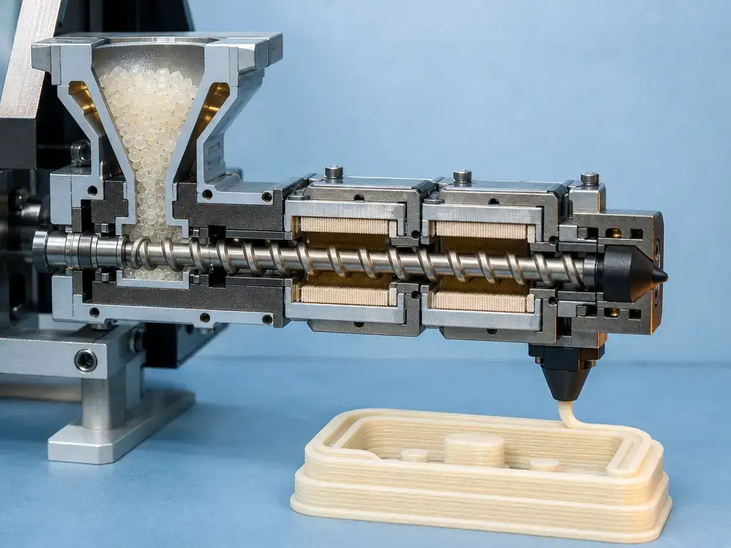
Bulk feeding introduces control dynamics that are less apparent in filament systems. Hopper level, pellet shape, fines, screw fill, barrel temperature, melt viscosity, and nozzle back-pressure can all affect delivery. During starts, stops, corners, and commanded-flow changes, melt pressure can lag machine motion. A stable screw revolutions-per-minute setting does not necessarily produce a stable deposited road. Research on fused granulate fabrication has measured deposited-road geometry and developed compensation approaches for these transients. [23]
Nozzle diameter, commanded bead width, measured bead width, and layer height must be treated as separate values. Die swell, nozzle gap, pressure transients, and cooling all affect the final road shape. [18] [19] Validation should therefore measure deposited geometry rather than assume that slicer settings match achieved dimensions.
After deposition, each bead must cool enough to support later layers while remaining hot enough to bond to adjacent material. Toolpath spacing, layer time, local cooling, enclosure conditions, and reheating from nearby roads all influence that thermal history. The usable process window depends on the polymer, nozzle, bead geometry, and part design.
A practical pellet-printing workflow is:
- Confirm the polymer or compound and its supplier requirements. SABIC lists ULTEM™ 9085 guidance of 120–130 °C for 4–6 hours to a maximum moisture content of 0.02%; an INEOS ABS guide lists residual moisture below 0.1% and 2–4 hours at 80 °C; BASF lists PA6-GF guidance of 0.03–0.06% moisture, a 0.15% maximum, and 4 hours at 80 °C. These are grade-specific examples, not universal pellet settings. [20] [21] [22]
- Dry and store feedstock to the defined target while limiting moisture pickup before printing. [20] [21] [22]
- Load pellets or granules into the hopper or material-conveyance system while avoiding contamination between materials. [9]
- Plasticize and meter material through the screw, heated barrel zones, and nozzle until pressure and delivery are established. [9]
- Synchronize delivered flow with motion and validate deposited roads on test lines, including starts, stops, corners, and steady paths. [23] [18]
- Build sliced layers while managing thermal conditions, because layer height and infill influence the relationship between extruder output and machine speed. [15]
- Inspect and post-process the part where needed, including machining or finishing for critical functional surfaces.
Pellet Extrusion, FGF, and Filament Printing: Key Terms
MEX is the ISO/ASTM process category for additive manufacturing in which material is selectively dispensed through a nozzle or orifice. [1] FDM and FFF are filament-associated labels and should not be used as blanket synonyms for pellet printing. Fused granulate fabrication, usually shortened to FGF, is a common industry and literature descriptor for continuous-bead pellet extrusion within MEX, but it is not the ISO/ASTM standards category. “Pellets” is the clearest default term for readers, although manufacturers and researchers also use “granules” and “granulate.” These distinctions matter because granulate-based additive manufacturing is not always continuous-bead extrusion: ARBURG’s Freeformer uses a plasticising screw with standard granulates but discharges individual droplets from its nozzle, making it distinct from the pellet-fed MEX process discussed here. [17]
Types of Pellet 3D Printer and Where LFAM Fits
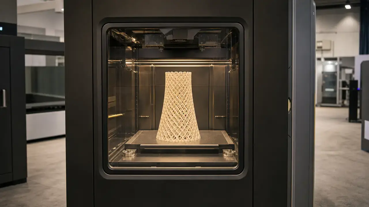
Pellet-fed MEX systems may be configured as compact enclosed industrial machines, gantry-based large-format systems, robotic-arm cells, or retrofit pellet extruders mounted on existing motion platforms. These are machine architectures rather than separate process categories. Each can use bulk feed and screw-driven nozzle deposition, while differing in moving mass, enclosure feasibility, accessible build geometry, thermal management, hopper integration, and material-transfer arrangements. [1] [9]
LFAM commonly refers to the larger end of this landscape, where build envelopes and deposited roads are often larger. A pellet machine need not be multi-meter scale, however. The WASP 60100 HDP lists a Ø600 mm × 1000 mm print volume, output up to 500 g/h, 1 mm and 2 mm nozzles, and layer-resolution settings from 0.1 mm to 1.5 mm. [10] The WASP CUBO HDP lists a 1200 × 1200 × 1200 mm build volume, a standard 5 mm nozzle, optional 1.2 mm, 2 mm, 3 mm, and 8 mm nozzles, and a maximum hotend temperature of 300 °C. [11] These are named-device specifications, not general performance limits.
| Characteristic | Filament-fed MEX (commonly) | Pellet-fed MEX (commonly) | Practical implication |
|---|---|---|---|
| Feedstock delivery | Spool and filament drive | Hopper, bulk conveyance, and screw | Pellets require storage, transfer, and contamination-control procedures. |
| Metering behavior | Filament advance is the immediate feed action | Screw rotation and melt-pressure development govern delivery | Starts, stops, and corners may require different tuning and validation. |
| Material preparation | Filament condition and spool path | Pellet drying, storage, hopper cleanliness, and bulk flow | Material control moves upstream into handling and preparation. |
| Likely bead scale | Often narrower deposited roads | Can support larger deposited roads | Larger roads can reduce coverage time but limit fine geometric detail. |
| Start-stop control | Retraction and filament-pressure management | Screw, melt-pressure, and motion synchronization | Deposited geometry should be measured rather than inferred from commands. |
| Operational consequences | Spool changes and filament availability | Hopper replenishment and compound availability | Selection depends on part size, feedstock form, finish needs, and workflow. |
Performance Metrics That Matter
A pellet printer’s advertised nozzle size or layer setting does not directly describe part quality. Travel speed is carriage motion; deposition speed is motion while material is placed; mass throughput is material delivered per unit time; delivered-flow or volumetric accuracy is how closely actual delivery follows the command; and total completion time includes setup, drying, cooling, finishing, and inspection.
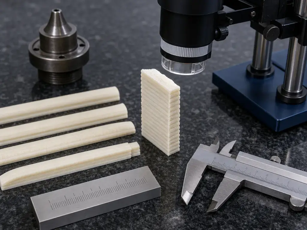
Nozzle diameter, commanded bead width, measured bead width, and layer height are related but non-interchangeable. Die swell, nozzle gap, pressure transients, and cooling affect the deposited result. [18] [19] In one ABS MEX study, measured die-swell ratios ranged from about 1.12 to 1.56 under the tested conditions, illustrating why a nominal nozzle opening is not a measured road width. [18]
| Outcome | What is measured | How to report | Common trap to avoid |
|---|---|---|---|
| Tolerance | Permitted dimensional variation | Feature, nominal size, limits, acceptance method | Calling a slicer increment a tolerance |
| Geometric accuracy | Deviation from intended geometry | Feature, axis, measurement method, error statistic | Equating accuracy with repeatability |
| Repeatability / precision | Variation among repeated prints or features | Sample count n, conditions, range or standard deviation | Reporting one successful print |
| Surface texture / roughness | Surface profile or texture | Surface orientation, method, Ra/Rz or qualitative state | Treating layer height as roughness |
| Flow / volumetric accuracy | Actual versus commanded material delivery | Command, measured mass or volume, interval | Inferring flow from screw setting alone |
| As-printed versus machined | State of the evaluated surface | Clearly identify the part condition | Assigning machined results to printing alone |
NIST test-artifact work emphasizes defined artifacts and measurement methods for revealing machine, material, and process behavior. The artifact and associated files are experimental tools that can be revised as the evaluation goal changes. [24] [25] For any claimed result, identify the measured feature and axis, the measurement method, the as-printed or machined condition, the sample count n, and the statistic reported. A controlled test should include representative straight roads, corners, starts, stops, and walls because transient delivery errors can appear even when average flow seems stable. [23]
Named specifications provide scale context, not transferable accuracy or finish claims. The WASP 60100 HDP lists output up to 500 g/h, 1 mm and 2 mm nozzles, and layer-resolution settings from 0.1 mm to 1.5 mm. [10] Massive Dimension’s MDAC50-50 robotic cell lists output up to 50 lbs/hour, nozzle sizes from 6.0 mm to 15.0 mm, a maximum extruder temperature of 450 °C, and an approximate build volume of 33 m³. [14] A CEAD transparent-lamp case study used a 3 mm layer height and 6 mm layer width for that project, showing that coarse deposited geometry can be an intentional production or visual choice rather than a general benchmark. [13]
| Spec line item | What it actually means | What else to ask for | How to validate |
|---|---|---|---|
| Output | A stated material-delivery rate under stated or unstated conditions | Polymer, nozzle, temperature, path, duty cycle | Weigh delivered material over timed representative paths |
| Nozzle options | Available or compatible orifice sizes | Measured bead-width range and feature limits | Print and measure roads, corners, walls, and seams |
| Thermal environment | Heater, bed, chamber, or extruder capability | Sensor locations, stability, and conditions throughout the build volume | Log temperatures during a representative build |
| Drying and material handling | Feedstock-preparation workflow | Dryer target, storage exposure, hopper procedures | Record moisture condition and handling history |
| Supported materials | Materials claimed as usable | Qualified grades, compounds, and test conditions | Review grade-specific samples and test records |
| Measurement evidence | A stated result or example part | Artifact, method, sample count, and statistic | Repeat the documented test under defined conditions |
Materials and Process Preparation
Pellet availability does not establish printability, a stable process window, or qualification for a particular part. Feedstock specification, handling, process settings, and intended-use requirements still need to be defined. [2] [26] The ULTEM 9085, ABS, and PA6-GF drying targets above are supplier examples for named grades, not rules for all pellets. In a material- and setup-specific PEI pellet-extrusion study, undried specimens showed voids up to 0.3 mm, illustrating the potential consequence of uncontrolled moisture without making it a universal result. [8]
Consistent pellet geometry and limited fines can help bulk flow, while fines, segregation, bridging, abrasive fillers, excessive residence time, or excessive temperature can destabilize processing or degrade the melt. Recycled feedstock should enter pellet extrusion only after preparation and qualification: control the source, screen contamination, dry the material, assess flow or viscosity consistency, and print representative test parts. An MIT recycled-FGF workflow includes sorting, washing, drying, and re-extrusion, while one recycled rPET/rHDPE study re-dried pellets at 70 °C for 12 hours before printing. [29] [28] Any mechanical-property campaign should document the polymer or compound, virgin or recycled status, filled or unfilled condition, drying or conditioning, bead and build orientation, specimen geometry, test method, sample count, and as-printed or post-processed state. [26]
Applications of Pellet Extrusion 3D Printing
Pellet extrusion is commonly considered for tooling, molds, near-net-shape preforms, and other large parts where material coverage and planned finishing matter more than fine as-printed detail. Screw-assisted granule-extrusion literature includes both small and large systems, while hybrid manufacturing cells provide a practical context for printing bulk geometry before machining selected surfaces. [3] [14] Large design or architectural components can also fit when the intended geometry is compatible with the deposited-road scale and the project accepts process development.
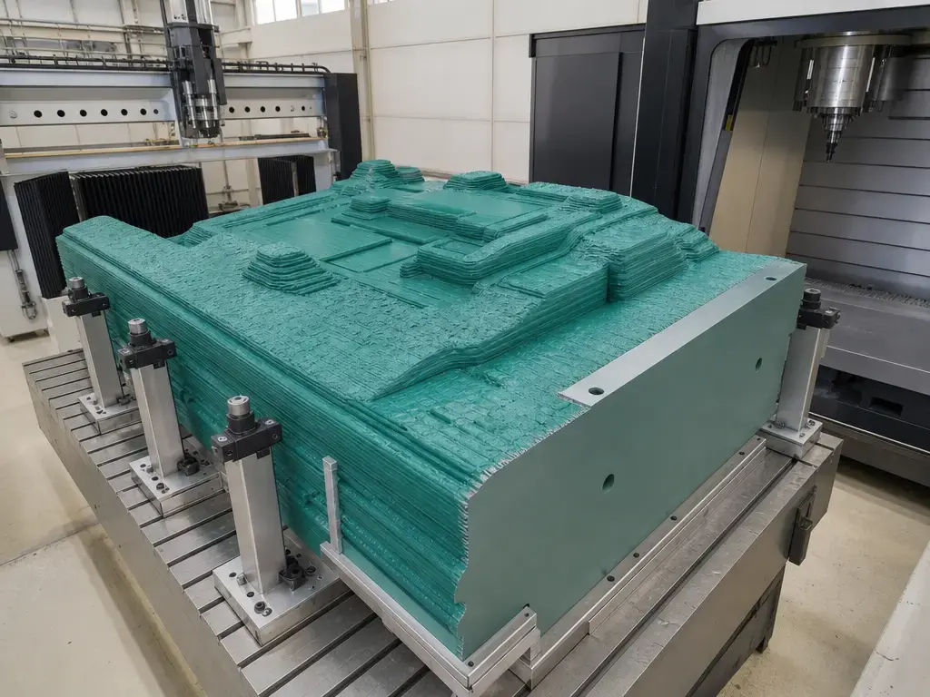
Pellet-fed MEX is generally a poor fit when the primary need is fine detail, smooth as-printed surfaces, tight unmachined tolerances, frequent material changes, or minimal purge material. Those requirements can conflict with bulk feed, larger deposited roads, pressure transients, and the machining allowance often used in near-net-shape workflows.
Better fit when:
- The required part size makes bulk material delivery and larger deposited roads useful.
- The geometry accepts the planned bead scale or includes machining allowance for critical features.
- The polymer or compound has been prepared and qualified for the intended process.
- Inspection, machining, sealing, or other finishing steps are defined before production.
Limitations and Failure Modes
Failure mechanisms should be separated from their visible signatures. Moisture-related defects can appear as bubbles, porosity, or voids; the PEI study cited above is one material-specific example. [8] Inconsistent bulk feeding, screw-pressure variation, or motion mismatch can appear as shifted bead placement or uneven roads. Start-stop and corner transients can produce blobs, thinning, gaps, or defective seams when delivered flow does not follow path demand. [23]
Scale adds constraints beyond build volume. Temperature gradients, uneven cooling, and long layer times can contribute to warpage and inconsistent interlayer bonding across a large part. Larger extruders also add moving mass, while bulk systems require space for dryers, hopper access, material conveyance, purge handling, ventilation, and heated-material safety procedures. Robotic cells add reach limits, collision planning, guarding, and facility-infrastructure requirements. In an ORNL multiplexing context, large and heavy extruders were reported to struggle with unreliable flow below about 10% of maximum flow rate; this is a system-specific finding, not a universal pellet-printing threshold. [16]
Maximum extruder output does not automatically mean a shorter usable-part cycle. Layer height, infill, toolpath conditions, setup, drying, thermal stabilization, cooling, machining, finishing, and inspection can dominate elapsed time for a controlled part. [15] Structured test artifacts and documented measurements help distinguish a high-output deposition demonstration from a repeatable manufacturing process. [24]
Current Research and Market Context
Current pellet-extrusion research focuses on making high-output deposition more measurable and controllable rather than simply increasing machine size. Screw-extruder work has modeled relationships among screw speed, temperature, and flow rate, while ABS studies have developed analytical predictive models for screw-extrusion behavior. [4] [7] High-temperature research involving PEEK provides another example of efforts to manage thermal stability during screw-based processing. [6] Other work measures deposited roads and applies transient compensation to reduce the mismatch between commanded flow and deposited geometry. [23] Multiplexed extrusion is another technical direction: distributing output among multiple units may increase throughput without relying only on one larger moving extruder. [16] The engineering trade-off remains output, low-flow controllability, deposited geometry, and resulting part structure.
Is a Pellet 3D Printer Right for Your Project?
A pellet 3D printer is a reasonable fit when the part size, acceptable bead scale, selected material, process controls, and finishing plan align. Maximum output alone is not a sufficient selection criterion.
The decision should be based on a validated material-process-part combination. Print representative geometry with documented handling and machine settings, then measure the features that matter to the part. NIST test artifacts provide a structured basis for evaluating geometry and surface outcomes, while ASTM F3489-23 provides reporting guidance for static mechanical testing of MEX polymer specimens. [24] [26] ISO/ASTM 52924 also provides a classification framework for mechanical, physical, and geometrical properties of polymer additive-manufactured parts in the as-built condition. [27]
Use project review to confirm the following:
- Is the part large enough that throughput and bead scale are relevant?
- Can the design tolerate coarse deposited roads or include machining allowance?
- Is the required polymer or compound available and qualified for the process?
- Can drying, storage, and hopper handling be controlled to a documented target?
- Can geometry be validated with an artifact, measurement method, sample count, and statistic?
- Is post-processing acceptable within the total cycle-time plan?
FAQ
What is a pellet 3D printer?
A pellet 3D printer is a material-extrusion machine that uses polymer pellets, granules, or granulate instead of continuous filament. It builds parts from 3D model data by selectively dispensing material through a nozzle or orifice, layer by layer. [1] Many systems use a hopper-fed screw extruder to convey, melt, pressurize, and deposit feedstock as a continuous bead. [9]
What is pellet extrusion 3D printing, and is it the same as FGF?
Pellet extrusion 3D printing describes MEX using bulk granulated feedstock. MEX is the formal ISO/ASTM process category for material selectively dispensed through a nozzle or orifice. [1] FGF is a common industry and literature descriptor for continuous-bead pellet extrusion within MEX, not a separate formal standards category. [23]
How does a pellet-fed 3D printer work?
Pellets are typically dried when required by the selected polymer, loaded into a hopper, conveyed by a screw through heated zones, and pushed through a nozzle along a programmed toolpath. [9] Because screw-driven melt pressure can lag motion changes, deposited roads should be measured and tuned at starts, stops, corners, and steady paths. [23]
What is a granule extruder 3D printer?
A granule extruder 3D printer is another common name for a pellet-fed machine. Product literature and research use pellets, granules, and granulate inconsistently, but the functional distinction is bulk material feeding through a hopper and screw-based extrusion system rather than a continuous filament path. [9] Not every granulate process deposits a continuous bead, however. [17]
What is a large-format pellet 3D printer?
A large-format pellet 3D printer is generally a pellet-fed MEX system configured for larger parts, often using gantry or robotic motion and larger deposited roads. There is no universal build-volume threshold for LFAM. For named-device context, the WASP CUBO HDP lists a 1200 × 1200 × 1200 mm build volume. [11]
Are pellet 3D printers faster than filament printers?
They can deliver more material per unit time, but throughput is not the same as completed-part lead time or geometric capability. CEAD reports recent E40 tests reaching 60 kg/hour with a 4–24 mm nozzle range, depending on material, configuration, and toolpath. [12] Drying, setup, cooling, finishing, and low-flow controllability can still govern the usable production cycle. [15] [16]
Can a pellet 3D printer use recycled plastic?
Potentially, but only with preparation and qualification; there is no universal guarantee. Recycled material requires source control, contamination screening, drying, and flow-consistency checks before representative print trials. [28] [29] Research on transient compensation in recycled and filled polypropylene FGF also shows why deposited-road behavior should be measured rather than assumed from feedstock identity alone. [23]
Sources
Sources include standards excerpts, peer-reviewed research, government guidance, academic theses, and manufacturer documentation. Manufacturer specifications are presented as named-device claims rather than general performance benchmarks.
- ISO/ASTM 52900:2021 additive manufacturing and material extrusion definitions
- ISO/ASTM 52903-1 feedstock supply-chain excerpt
- Screw-assisted 3D printing with granulated materials: systematic review
- Design of a Screw Extruder for Additive Manufacturing
- Extrusion-based additive manufacturing technologies review
- PEEK screw-extrusion additive manufacturing stability study
- ABS screw-extrusion analytical model study
- PEI pellet extrusion additive manufacturing moisture and voids study
- JuggerBot 3D fused granulate fabrication process page
- WASP 60100 HDP specifications