
Summary
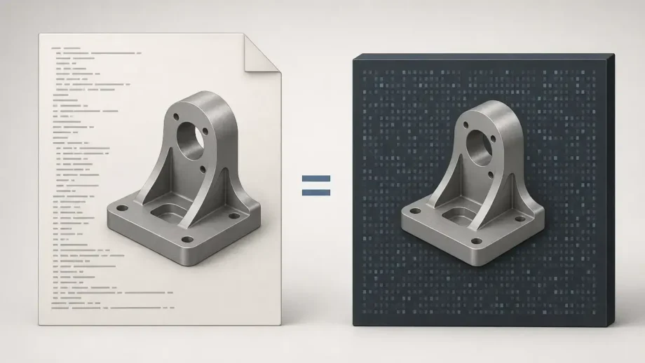
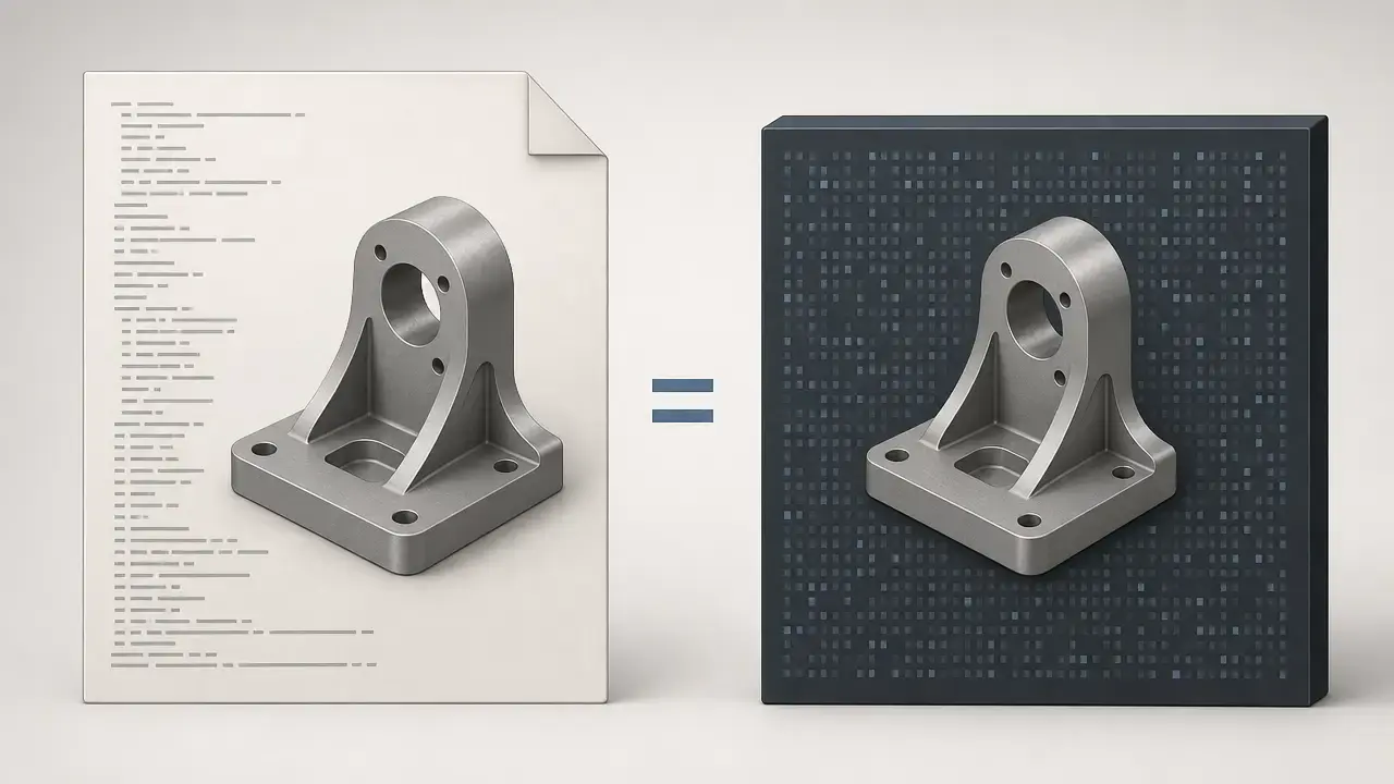
A Parasolid file is usually Parasolid XT data, most often saved as .x_t or .x_b, and used to exchange precise boundary-representation CAD geometry between Parasolid-aware applications. It is meant for editable solids and surfaces rather than slicer-ready meshes, so it usually appears earlier in the workflow than STL or 3MF. Siemens describes Parasolid XT as the open, published Parasolid data format, while STEP belongs to the ISO 10303 family and is widely used for standardized CAD, CAE, PDM, and preservation workflows. [2] [6] [13] [14] [15]
Use Parasolid XT when both sides already support Parasolid workflows.
Use STEP when you need ISO-standardized exchange or preservation.
Use STL or 3MF when you need tessellated output for slicing. [2] [6] [14] [15]
What Is a Parasolid File?
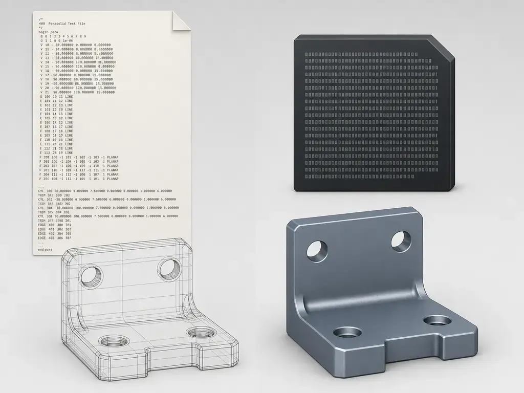
If you ask what is a Parasolid file, the practical answer is simple: it is a Parasolid XT exchange file for exact CAD geometry. In everyday use, that usually means .x_t or .x_b data moving solid or surface models between systems, not a native authoring database and not a final print file. If you ask what is an .x_t file, it is the text form of that same Parasolid XT family. [2] [10]
The key distinction is kernel versus file. Parasolid itself is the geometry engine used inside many applications to create, edit, and evaluate model geometry. Siemens describes it as a 3D geometric modeler with 900+ functions, licensed to 200+ independent software vendors, and used across more than 350 applications based on the Parasolid XT data format. Those Siemens ecosystem figures help explain why the Parasolid file format appears so often in CAD exchange workflows. [1] [18]
Why use XT instead of an application’s native save file? Siemens positions Parasolid XT as an open, published data format that gives Parasolid-based applications translation-free interoperability. That makes it useful when both sides already use Parasolid and you want exact CAD geometry to move with minimal reinterpretation. It is not the same as an ISO standard and should not be described that way. For broader neutral exchange and long-term preservation, STEP is the better-known standardized option in the ISO 10303 family. [2] [14] [15]
Parasolid .x_t vs .x_b
In most workflows, .x_t and .x_b are typically the same Parasolid model encoded as text or binary, subject to exporter/importer support and version settings. The legacy XT reference describes text as ASCII and .x_b as neutral binary, while ANSYS says both text and neutral-binary Parasolid files are platform independent. ANSYS also notes that neutral-binary files are compressed and not human readable, while text files are human readable but take more space. [7] [10]
The practical rule is straightforward: choose the form the recipient supports best, then match the Parasolid version they can read. If you are troubleshooting a flaky translation path, .x_t is easier to inspect. If you only care about compact transfer, .x_b is often the tidier handoff. [7] [10]
Table 1 compares the two common encodings. [7] [10]
| Aspect | .x_t |
.x_b |
Editorial caution |
|---|---|---|---|
| Encoding | Text, usually ASCII. [10] | Neutral binary. [10] | Legacy XT docs also mention bare and typed binary, but .x_t and .x_b are the common interchange choices. [10] |
| Human readability | Human readable. [7] [10] | Not human readable. [7] | Text is easier to inspect when debugging import problems. [7] |
| File size tendency | Usually larger. [7] | Usually more compact; ANSYS calls neutral binary “compressed.” [7] | No reliable universal size ratio was found. [7] |
| Compatibility | Works where text Parasolid is accepted. [7] | Works where neutral-binary Parasolid is accepted. [7] | Ask the recipient which encoding and Parasolid version they support. [7] [10] |
How to Open / View / Convert a Parasolid File
Opening a Parasolid file, viewing it, and editing it are different tasks. A viewer may let you inspect and measure geometry, while a CAD import path determines whether you can heal, modify, or re-export the model. That matters because some tools document Parasolid XT support as a viewing workflow, while others document explicit import and export ranges. [3] [4] [5] [6] [7]
Support also depends on file naming, version range, and the exact exchange path. The legacy April 2008 XT reference recommends .X_T and .X_B for part files and .P_T and .P_B for partition files, and it also lists older .xmt_txt, .xmp_txt, .xmt_bin, and .xmp_bin variants. That naming history is useful for troubleshooting, but it does not guarantee that a current application supports every legacy variant. [10]
Support matrix (as documented).
| Tool | View | Import / Export | Version or license caveats |
|---|---|---|---|
| JT2Go | Yes, as a free viewer for JT and Parasolid XT data. [4] | Siemens says JT2Go v13.3 added direct interaction with Parasolid XT files, and the cited materials describe a viewing and measuring workflow. [3] [4] | Viewer context on the cited pages, not a general CAD editing claim. [3] [4] |
| Onshape | Yes, after import into a document. [5] | Import: Parasolid B-rep .x_t/.x_b v10.0–v38.1. Export: .x_t/.x_b v25.0–v37.0. [5] |
Onshape calls Parasolid its preferred import format. [5] |
| Fusion | Supported format listing only. [6] | Parasolid Binary .x_b and Parasolid Text .x_t are listed; export is not listed on the cited page. [6] |
Autodesk says available formats depend on license. [6] |
| ANSYS | Yes, as a Reader. [7] | DesignModeler imports and exports .x_t, .x_b, .xmt_txt, and .xmt_bin. [7] |
Release 2024 R2 page; text and neutral-binary Parasolid are described as platform independent. [7] |
| Rhino | Not stated on the cited page. | Export: Parasolid .x_t. [8] |
Rhino says Parasolid files are always in meters and scales export if Rhino units differ. [8] |
Before opening or sending a Parasolid file, check:
- The extension. Common part-file names are
.x_tand.x_b, while the legacy reference also lists.P_Tand.P_Bfor partition files plus older.xmt_txt,.xmp_txt,.xmt_bin, and.xmp_binvariants. [10] - The requested Parasolid version window at both ends of the exchange. [5] [7]
- Whether the recipient wants text or neutral-binary Parasolid. [7] [10]
- Whether you are sending a part, an assembly, or a file that relies on instancing. [7] [10]
- What the receiving workflow expects for units and scale. [7] [8] [17]
- Whether the file source is trusted. Siemens ProductCERT advises not to open untrusted XT files. [9]
A recipient-first conversion workflow is usually safest. If the target application documents direct Parasolid support, export to the specific version range it accepts. If it does not, move through a validated intermediate format such as STEP only after confirming the downstream toolchain. That keeps the process anchored to documented compatibility instead of assuming every CAD package translates Parasolid the same way. [5] [6] [7] [14]
Parasolid XT vs STEP vs STL/3MF
Parasolid XT is the Parasolid-native interchange path. Siemens describes it as open and published, and specifically positions it for translation-free interoperability between Parasolid-based applications. If both sides of the exchange already use Parasolid-aware software, XT is often the most direct way to hand off exact CAD geometry. [2]
STEP serves a different purpose. NIST describes ISO 10303, commonly known as STEP, as a widely adopted standard for CAD, CAE, and PDM data exchange, system integration, visualization, and long-term preservation of product information. ISO 10303-1:2024 is the current overview and fundamental-principles document for the series, and ISO 10303-242:2025 is the current managed model-based 3D engineering document. In practice, STEP is the safer comparison when you need a standardized exchange path across different CAD ecosystems. That still does not guarantee full preservation of proprietary feature history, because what arrives depends on what the exporter writes and what the importer can interpret. [14] [15] [16]
STL and 3MF solve a downstream manufacturing problem rather than an editable CAD interchange problem. They are tessellated outputs used for mesh and slicing workflows, so they usually appear at the end of the chain, after the Parasolid or STEP handoff rather than instead of it. [6]
Inside the Parasolid File Format
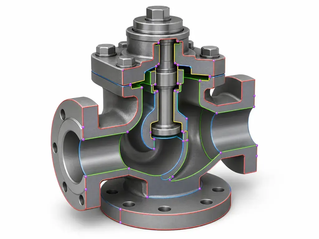
A boundary representation, or B-rep, describes a solid in terms of its bounding faces, edges, and vertices together with the adjacency relations between them. That matters because a Parasolid file is not just a collection of surfaces. It is a topological description of how exact geometry is connected into sheet or solid form. [13]
In Parasolid XT, that structure is described with entities for bodies, regions, shells, faces, loops, edges, vertices, and related topology. The legacy April 2008 XT reference is still useful for understanding this structure, but it should be treated as a legacy reference rather than the latest XT revision. [10]
XT is a published format, and the legacy reference also includes ASSEMBLY and INSTANCE entities, so the file can carry more than isolated surfaces or solids when the exporter writes that structure. Newer Parasolid context also allows B-rep, mesh, and implicit representations to coexist in one model. What actually transfers still depends on the source application, exporter settings, and importer support. [2] [10] [12]
Core things a Parasolid file may describe:
- Solid and sheet bodies plus topology entities such as shells, faces, loops, edges, and vertices. [10]
- Assembly and instance structure when the exporter writes it. [10]
- Attributes such as names or colors in application-specific workflows, with no reliable universal guarantee found across tools. [7] [10]
- In current Parasolid contexts, mixed B-rep, mesh, and implicit content can coexist, but only if the application and exchange path support it. [12]
What usually transfers vs what doesn’t.
| Category | Examples | Typical outcome | Source anchor |
|---|---|---|---|
| Core geometry/topology | B-rep solids and surfaces, plus faces, edges, vertices, and adjacency. | Usually the strongest part of the exchange. [10] [13] | B-rep definition and XT structure. |
| Optional metadata | Names, colors, attributes, named selections. | May transfer, but behavior varies by application and no reliable universal guarantee was found. [7] [10] | Tool-dependent metadata handling. |
| Native CAD intelligence | Feature trees, sketches, parametric intent, mates, configurations. | Usually lost in translation because proprietary parametric intelligence is not transmitted in data translation. [11] | Siemens data-integrity guidance. |
Version Compatibility: Kernel vs XT vs Application Support
Siemens describes two-way version compatibility as a design goal, but real workflows are bounded by what each application version supports and what version the exporter writes. That is why a Parasolid file can still fail even when both products advertise Parasolid support. [2] [5]
- XT design intent. Siemens says two-way Parasolid version compatibility enables exchange between applications based on different versions of Parasolid. [2]
- Exporter target version. The sending application must be able to write a version the recipient actually accepts. [5]
- Importer supported window. Onshape, for example, documents Parasolid import from v10.0 to v38.1 and export from v25.0 to v37.0. [5]
That three-layer model explains why .x_t versus .x_b is only part of the story. Choose the version first, then choose the encoding the recipient handles best. [5] [7]
Units & Scaling
Multiple documented workflows treat Parasolid geometry as meters or map 1 unit to 1 meter; scaling can still be a translation pain point. ANSYS Mechanical says it automatically sets Parasolid part or assembly length units to meters, which it describes as the unit used internally by Parasolid for dimensioning solid parts. Siemens’ JT v10 reference adds that a typical mapping of 1 unit = 1 metre is used by all Siemens applications and almost all other adopters. [7] [17]
Rhino documents the same issue in a very practical way: its help page says Parasolid files are always in meters, and exported geometry is scaled if Rhino units are not meters. A file can therefore import successfully and still be the wrong size for the next user. [8]
To avoid surprises:
- Measure a known dimension after import before trusting the handoff. [8] [17]
- Confirm the recipient’s expected units before final release. [7] [17]
- If unit expectations are unclear, keep a STEP backup alongside the Parasolid file. [14]
Assemblies, Instancing, and What ‘Assembly’ Does Not Mean
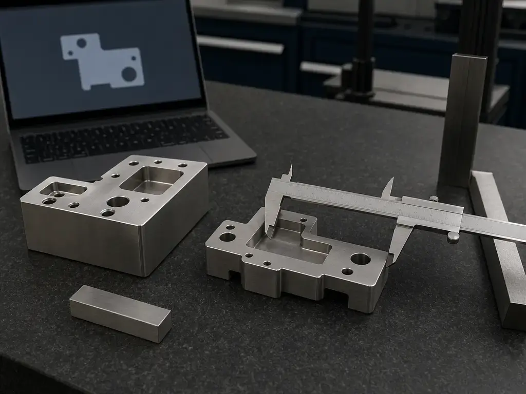
Parasolid XT can carry assembly and instance structure at the format level. The legacy XT reference includes ASSEMBLY and INSTANCE entities, and it describes an instance as a reference to a body or assembly with an optional transform. ANSYS also documents instance generation in its Parasolid workflow when the relevant import property is enabled. In practical terms, repeated hardware or repeated geometry may come through as instances in some workflows rather than as separately copied solids. [7] [10]
That does not mean the receiving system will recreate a fully native assembly environment. Siemens’ data-integrity guidance says parametric intelligence is proprietary and not transmitted in data translation, so mates, constraints, configurations, suppression states, and feature-tree behavior should be treated as importer-dependent rather than guaranteed Parasolid content. [11]
Common Failure Modes + Security Note
The first things to check are usually version mismatch and encoding mismatch. If a recipient only imports a bounded Parasolid window, or expects one exchange form and receives another, the file may fail even when the geometry itself is fine. Troubleshooting should start with the exporter’s target version, the importer’s documented window, and whether the file is .x_t or .x_b. [2] [5] [7]
Other failures are subtler. A file can be corrupt, can arrive at the wrong scale, or can contain data types that the receiving application does not fully support. The legacy XT reference notes that unexpected non-printing characters can cause Parasolid to reject a text transmit file as corrupt, and current Parasolid context also includes mixed B-rep, mesh, and implicit models that may exceed what a specific importer handles. [10] [12]
Keep the security advice minimal and practical. Siemens ProductCERT SSA-222019 warns of X_T parsing vulnerabilities and recommends not opening untrusted XT files. Use current software, validate the source, and prefer a viewer or sandboxed environment before moving the file into production CAD. [9]
Current Context: Mixed Modeling
Siemens’ Parasolid v39.0 post, dated August 25, 2026, describes a modeling context in which B-rep geometry, meshes, and implicit representations can coexist within a single digital model. That matters because it reflects current expectations around scan-to-CAD, reverse engineering, lattice-heavy additive work, and hybrid modeling rather than a strictly single-representation kernel. [12]
The boundary is important: this does not mean every .x_t or .x_b export contains mixed-model content. Exported content still depends on what the source application writes and what the importer supports, so the file extension alone does not tell you whether a given handoff carries only classic B-rep or something broader. [12]
Practical Conclusion: When a Parasolid File Is the Right Handoff
A Parasolid file is the right handoff when the receiving chain is already Parasolid-aware and you want exact CAD geometry to move with minimal reinterpretation. Use STEP when you need a standardized ISO 10303 exchange path or a better preservation-oriented handoff across unlike CAD systems. Use STL or 3MF when the destination is slicing rather than editable CAD. The safest rule is still recipient-first: choose the format the downstream system documents cleanly, then verify version, units, and geometry before trusting the transfer. [2] [6] [14] [15] [16]
FAQ
What is a Parasolid file?
A Parasolid file is usually a Parasolid XT exchange file used to move exact CAD geometry between Parasolid-aware applications. It commonly appears as .x_t or .x_b and carries B-rep geometry rather than a slicer-oriented mesh. [2] [13]
What is an .x_t file?
An .x_t file is the text form of Parasolid XT. The legacy XT reference describes it as text, usually ASCII, and ANSYS says text Parasolid files are human readable. [7] [10]
What is an .x_b file?
An .x_b file is the neutral-binary form of Parasolid XT. ANSYS says neutral-binary Parasolid files are compressed and not human readable, while the legacy XT reference describes neutral binary as machine independent. [7] [10]
Parasolid .x_t vs .x_b: which should I use?
Use the form the recipient supports best. .x_t is easier to inspect, while .x_b is usually more compact, but version support matters as much as encoding choice. [7] [10]
How do I open a Parasolid file?
Start with software that explicitly documents Parasolid XT support. JT2Go is a free viewer for JT and Parasolid XT data, and Siemens says version 13.3 added direct interaction with Parasolid XT files. If you need editable import, check the application’s documented version window, not just the fact that it mentions Parasolid. [3] [4] [5]
Expert: Why do Parasolid files fail to import if two-way version compatibility exists?
Because the compatibility claim is only one layer. Siemens describes two-way Parasolid version compatibility as a design goal, but the exporter still has to write a version the recipient supports, and the importer still has to accept that version window. Onshape’s published Parasolid window, for example, is narrower than “all versions forever.” [2] [5]
Expert: Why do Parasolid files sometimes come in at the wrong scale or units?
Because multiple documented workflows treat Parasolid geometry as meters or map 1 unit to 1 metre, and applications may scale on import or export. ANSYS describes a meters-based Parasolid workflow, Rhino says Parasolid files are always in meters on export, and Siemens documents the common 1 unit = 1 metre convention. Check one known dimension after import. [7] [8] [17]
Sources
- Siemens — Parasolid product page. https://www.siemens.com/en-us/products/plm-components/parasolid/
- Siemens — Parasolid Data Access and Translation. https://www.siemens.com/en-us/products/plm-components/parasolid/data-access-translation/
- Siemens PLM Components Blog — Free Parasolid model viewer now available. https://blogs.sw.siemens.com/plm-components/parasolid-model-viewer/
- Siemens — JT2Go viewer page. https://www.siemens.com/en-us/products/plm-components/jt/jt2go/
- Onshape Help — Supported File Formats. https://cad.onshape.com/help/Content/File/supported_file_formats.htm
- Autodesk Fusion Help — Supported file formats. https://help.autodesk.com/view/fusion360/ENU/?guid=TPD-SUPPORTED-FILE-FORMATS
- ANSYS Help — Parasolid CAD integration. https://ansyshelp.ansys.com/public/Views/Secured/corp/v242/en/ref_cad/cadParasolid.html
- McNeel Rhino Help — Parasolid
.x_texport. https://docs.mcneel.com/rhino/mac/help/en-us/fileio/parasolid_x_t_export.htm - Siemens ProductCERT — SSA-222019 X_T parsing vulnerabilities. https://cert-portal.siemens.com/productcert/html/ssa-222019.html
- Parasolid XT Format Reference (April 2008, legacy Siemens document via third-party mirror). https://ww3.cad.de/foren/ubb/uploads/schulze/XT_Format_April_2008_tcm73-62642.pdf
- Siemens — How to manage CAD software data integrity. https://resources.sw.siemens.com/de-CH/white-paper-how-to-manage-cad-kernel-data/
- Siemens PLM Components Blog — Parasolid v39.0 advancing the future of geometry modeling. https://blogs.sw.siemens.com/plm-components/parasolid-v39-0-advancing-the-future-of-geometry-modeling/
- Springer open access article — B-rep definition. https://link.springer.com/article/10.1007/s00366-026-02379-1
- NIST — STEP widely adopted and used for CAD, CAE, and PDM exchange and preservation. https://www.nist.gov/news-events/news/2024/03/nist-contributes-new-modeling-capability-iso-product-data-interoperability
- ISO — ISO 10303-1:2024 catalog page. https://www.iso.org/standard/83105.html
- ISO — ISO 10303-242:2025 catalog page. https://www.iso.org/standard/84300.html
- Siemens — JT v10 file format reference. https://www.plm.automation.siemens.com/en_us/Images/JT-v10-file-format-reference-rev-B_tcm1023-233786.pdf
- Siemens PLM Components PDF — Parasolid factsheet. https://www.plm.automation.siemens.com/en_us/Images/Siemens-PLM-Components-Parasolid-fs_tcm1023-7381.pdf