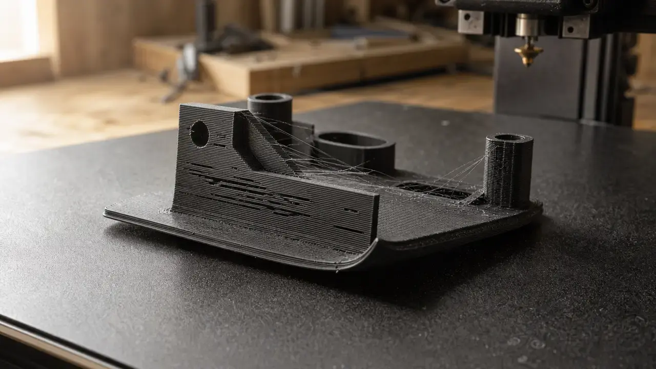

Quick start: diagnose the symptom before changing settings
3d print troubleshooting starts with the visible defect, but a defect is evidence rather than proof of one cause. This guide covers desktop filament-fed material-extrusion printers and desktop vat-photopolymerization systems. Additive manufacturing builds objects through the successive addition of material, so a flaw may originate in the model, slicer, machine motion, material condition, process settings, or post-processing before it appears on a part. [1]
The workflow below helps narrow likely cause classes before settings are changed. For resin handling, washing, curing, vat cleaning, and disposal, the exact printer instructions, material documentation, safety data sheet (SDS), and applicable local rules take priority over generic troubleshooting advice. [18]
Terminology and scope: read this before changing settings
Additive manufacturing (AM) is the standardized umbrella term for processes that join materials to make objects from 3D model data, usually layer by layer rather than primarily by removing material. ISO/ASTM 52900:2021, Additive manufacturing — General principles — Fundamentals and vocabulary, is Edition 2 of the International Standard, published on November 16, 2021, and comprises 28 pages. [1] In everyday use, “3D printing” is the broader label for the machines, materials, files, and finishing steps used to make a part.
This article focuses on desktop filament-fed material extrusion and desktop vat-photopolymerization systems, including SLA, MSLA, and DLP. It excludes pellet-fed extrusion, industrial-scale systems, and industrial repair workflows, where feedstock delivery, thermal control, safety procedures, and qualification requirements differ. The search phrase FDM print quality problems remains common, but FDM is a registered trademark of Stratasys; this guide therefore uses the generic technical terms FFF and material extrusion where possible. [4]
Step 0 — Digital and documentation preflight
Before treating a defect as a machine or material fault, inspect the prepared file. Model and slicer artifacts can resemble hardware problems: walls may be absent, thin features may not generate for the selected nozzle and line-width strategy, or planned travel may explain strings and surface marks. Cura’s Preview stage shows generated extrusion and travel paths, while X-ray view can reveal missing or unwanted geometry. Its documentation recommends checking the layer view before sending a job. [22]
Document the starting condition so later comparisons remain meaningful. Record the exact printer, nozzle or resin, material, active profile, environment, and maintenance status. The printer manual, material technical data sheet (TDS), and SDS are the higher authorities for operating limits, compatibility, and safe handling. ISO/ASTM 52902 describes test artefacts for geometric capability assessment, but does not prescribe a specific manufacturing procedure or machine settings for a test piece. [2]
- Preview the sliced layers before printing.
- Inspect travel paths and seam locations.
- Check for missing geometry and conditionally printable thin features.
- Record the exact printer model.
- Identify the active nozzle or resin.
- Record the material and selected profile.
- Note the environment and last maintenance.
- Do not change more than one variable at a time.
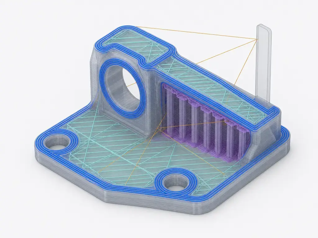
Fast diagnostic workflow: safe triage
Triage separates failures by when they appear: before printing in the model or sliced file; early in the build at the first layer; during the build in material delivery, motion, adhesion, or support generation; or after printing during washing, curing, and finishing. This prevents a visible result from being treated as proof of a single root cause.
Five-step triage sequence
- Preserve evidence: photograph the part, note the failure point, and stop if continued operation could be unsafe.
- Classify the symptom stage: digital preparation, first layer, mid-print material delivery, motion, unsupported geometry, resin separation, or post-processing.
- Complete the digital preflight: inspect the model, sliced preview, and generated toolpaths or exposure layout.
- Inspect the lowest-risk cause classes first, including visible contamination, material identity, accessible looseness, and maintenance status.
- Make one controlled change, then verify it using the same model and comparison method.
Stop rather than continue if the printer collides, makes abnormal mechanical noise, contains suspected cured resin debris, or requires vat cleaning whose approved procedure is unknown. Prusa’s SL1 guidance treats a platform-empty resin failure as a condition that should be stopped promptly, while Phrozen’s pre-print guidance includes checking the vat and build plate for cured material. [20] [21]
Symptom-to-first-action table: evidence, not proof
Use this table to choose an inspection order, not to assign a cause from appearance alone. Start with the file and sliced preview, then inspect accessible, low-risk conditions before changing a profile or dismantling equipment. [22]
A visible symptom is evidence, not proof — rule out slicer/model issues first.
| Visible symptom | Common cause classes to rule out | Inspect first (lowest-risk) | Safe next action |
|---|---|---|---|
| Bed non-adhesion | First-layer path, surface condition, material, machine setup | Sliced first layers and visible surface condition | Compare against a documented baseline. |
| Corner lift or warping | Part geometry, cooling environment, adhesion, material | Preview contact area and long edges | Check for environmental changes before altering settings. |
| Gaps or thin walls | Model geometry, wall-generation rules, material delivery | Preview walls, perimeters, and missing features | Revise the model or slicing strategy if paths are absent. |
| Blobs or zits | Travel paths, seam placement, pressure changes, material condition | Preview seams and travel locations | Run one controlled comparison using the same model. |
| Sudden XY offset | Collision, obstruction, loose motion components, file anomaly | Stop and inspect for collision evidence or looseness | Do not resume after a collision. |
| Rough top surface or pillowing | Top geometry, internal support, material flow, cooling | Preview top layers and structure beneath them | Compare the same test geometry after one change. |
| Platform empty but cured sheet in vat | Build-platform condition, support contact, vat-film condition | Inspect the vat and platform through the vendor workflow | Remove debris only by the manufacturer procedure; do not restart over debris. [16] [20] |
| Nothing cured anywhere | Resin selection, prepared file, optical path, LCD or light-engine fault | Confirm resin, file, and visible vat condition | Follow the manufacturer’s diagnostic procedure. |
3D printing problems not sticking to bed: first layer, warping, and elephant foot
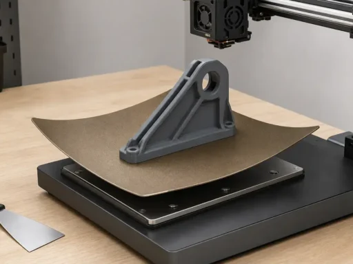
Bed adhesion is attachment between the first deposited material and the build surface. It differs from interlayer adhesion, the bond between successive deposited layers. Warping is distortion associated with uneven contraction and internal stress, often appearing as lifted corners or edges. A part that detaches immediately, a part that lifts later, and a part that remains attached but develops a widened lower edge — commonly called elephant foot — require different inspections.
Start with the lowest-risk evidence. Inspect whether the build surface is visibly contaminated, damaged, or carrying remnants from an earlier print. Then compare the nozzle-to-surface relationship with the printer’s documented first-layer setup method. Prusa describes first-layer calibration as setting the distance between the nozzle tip and print surface so material adheres and is slightly squished. [5] Next, inspect the sliced first layers: confirm that the part has adequate intended contact area and that any brim is generated in Preview. If corners lift only after several layers, inspect part shape, long edges, and possible drafts or uneven ambient conditions before assuming an immediate first-layer failure.
Verify each hypothesis with a controlled comparison. A small first-layer patch can show whether deposited lines are continuous and consistently attached across the usable surface. Repeat it on a clean surface using the documented preparation method, then compare the same model with and without a brim. If the patch adheres but a larger part later lifts, shift attention toward geometry and environmental stability. If the base spreads while attachment remains sound, record elephant foot separately from warping.
Under-extrusion, over-extrusion, and inconsistent flow
Under-extrusion can appear as gaps in or between printed layers, missing lines, weak-looking infill, or surfaces that do not close as the preview suggests. [10] Over-extrusion is a different pattern: excess material accumulates where planned paths are already present, producing crowded lines, ridges, or dimensional excess. Inconsistent flow may alternate between normal and sparse deposition, so a single profile adjustment can obscure the actual cause.
Use this decision path to separate file preparation, commanded flow, material delivery, and hotend behavior:
- If walls or features are absent in the preview, then investigate model geometry and thin-feature handling before the printer. The machine cannot deposit paths the slicer did not generate. [22]
- If the preview is complete but deposition is uniformly too sparse or too heavy, then record both the firmware flow factor and slicer extrusion multiplier. On Prusa systems, total flow is the firmware M221 flow multiplier multiplied by the slicer extrusion multiplier. [13]
- If flow varies during a print, then observe the spool path and drive system for spool drag, filament snagging, or visible drive slip before changing the profile.
- If restriction appears after printing for some time, then distinguish a partial clog from heat creep using low-risk observations. Heat creep can soften filament higher in the hotend, where it may bind and contribute to a clog. [11]
- If a nozzle or profile changed, then confirm that the active profile and nozzle are paired for the intended volumetric demand. Prusa warns that mismatched profiles and nozzle types can disrupt volumetric-flow calculations and contribute to under-extrusion or clogs. [12]
Firmware flow and slicer extrusion multiplier are separate controls, although both influence deposited material. On Prusa systems, changing one does not automatically alter the other. The manufacturer also notes that an appropriate extrusion-multiplier value can vary by material type, color, and even spool. [13] Record both settings before changing either one, and keep the spool identity fixed during a comparison whenever possible.
A partial clog may cause a persistent reduction in output, while heat creep often follows a time-related pattern and may be more likely in a warm room or enclosure. [11] [12] Neither conclusion should be drawn from a rough surface alone. Inspect the filament path, note when the symptom begins, and compare the result using the same small geometry.
Stop and escalate rather than repeatedly forcing filament through the system when clogs recur, the hotend assembly appears suspect, or heater and temperature-sensor behavior is abnormal. These conditions can involve thermal-control, assembly, or electrical faults and should be addressed only through the manufacturer’s service instructions.
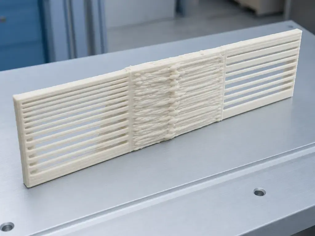
Stringing, blobs, rough top surfaces, bridging, and support defects
Stringing and oozing
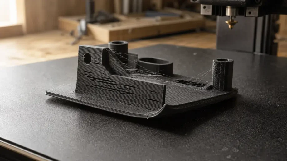
Stringing, or fine material drawn between separate features, can result from competing causes including travel behavior, thermal conditions, profile choices, and material condition. Begin with the sliced preview, especially travels between separate islands, rather than assuming every strand has the same origin. [22] Inspect the filament’s handling history and active profile, then make one controlled comparison using the same small model. Record whether any improvement in stringing creates another defect, such as poorer bridge quality.
Blobs, zits, and seam artifacts
Blobs, zits, and seam marks are localized excess-material features, not automatic proof of general over-extrusion. Possible causes include pressure changes at starts and stops, repeated restarts on small features, and planned seam placement. Inspect the preview for seam locations and short isolated paths first. A small vertical tower or other repeatable geometry can show whether marks occur at the same planned locations from layer to layer. Change one seam or profile variable, then compare the new print with the original.
Rough top surfaces, pillowing, and sparse top fill
Rough top surfaces and pillowing can begin below the visible surface. Relevant cause classes include insufficient internal foundation beneath the top paths, inconsistent flow, and cooling behavior that prevents deposited lines from stabilizing as intended. Inspect the preview for internal structure and the final top-path pattern before altering a profile. No reliable universal top-thickness figure exists; use the manufacturer profile, material guidance, and actual model geometry.
Bridging, overhang droop, and support-related roughness
Bridging is the printing of layers over thin air without supports. [14] It differs from supported geometry: a bridge is an intentionally unsupported feature, while supports are generated structures added to hold regions that would otherwise print in air. Inspect bridge paths, overhang regions, and generated support placement in Preview before printing. [22]
A denser support interface can increase contact between the object and support and reduce sagging at that boundary, but it also uses more time and material and can affect removal and surface finish. [15] Treat support-interface settings as a model-specific trade-off, not a universal remedy. Escalate from profile comparisons to machine inspection when the same defects persist across known-good files and controlled tests, or when they occur in locations not explained by the preview.
Motion and mechanical failures: layer shifting, ringing, and periodic Z artifacts
3D printing problems layer shifting
A true XY layer shift is a sudden displacement of all later features in one horizontal direction relative to the earlier part of the same print. It differs from warping, where the part itself distorts or lifts, and from a slicer problem, where the displacement is visible in the prepared file. For 3D printing problems layer shifting, inspect the preview first, then look for obstructions in axis travel, evidence of nozzle collisions, loose belts, and motor pulleys that may not be secured to their shafts. Prusa’s guidance includes checking that pulley set screws align with the flat on the motor shaft and that axes move freely without obstruction. [6]
Verify the diagnosis with a reduced-speed print of the same small model, observing whether the shift remains at a consistent height or direction. Stop and escalate if shifts follow collisions, recur across controlled tests, or involve inaccessible or damaged mechanical components. Do not attempt invasive motion-system repairs without the relevant service documentation.
Ringing or ghosting
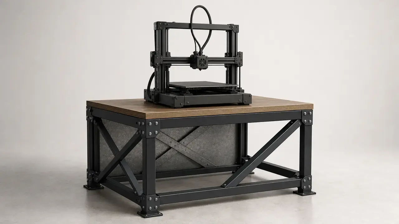
Ringing, also called ghosting, is a repeating echo-like pattern after corners or abrupt geometric changes. It is associated with vibration and can increase as print speed rises because the moving system must dissipate more energy during direction changes. [7] Inspect the printer’s support surface, visible belt condition, and whether surrounding furniture moves during printing. Compare the same small model at reduced speed before changing multiple motion settings. A stable surface and documented belt checks are appropriate first actions; hardware modifications are not a first-line diagnosis. [7]
Z banding or “Z wobble”
Periodic Z artifacts are repeating horizontal bands or surface changes that recur at regular vertical intervals. If the same spacing appears across different models, a mechanical contribution such as frame rigidity, vertical-motion alignment, or repeating lead-screw-related behavior is more plausible than random material-delivery variation. Polymaker describes Z-axis wobble as repeated minor layer shifts and states that slicer settings will not fix a frame- or rigidity-related issue. [23]
Compare several prints and note whether bands recur at similar Z intervals while confirming that the sliced preview has no matching geometry changes. Inspect accessible frame and motion components only within the manufacturer’s maintenance guidance. Escalate persistent periodic artifacts rather than prescribing lead-screw replacement, hotend tightening, or other invasive mechanical changes.
Resin 3D printing problems and solutions: failure-mode map and safe boundaries
Classify resin failures by where cured material is found and whether any planned part formed. A platform that rises with no print attached while a flat cured sheet remains at the tank bottom is a documented Formlabs non-adherence pattern, but it is not a universal diagnosis for every SLA, MSLA, or DLP printer. [16] On Prusa SL1 and SL1S systems, a failed first layer can leave a flat cured blob on the FEP film; Prusa advises stopping the print promptly in this situation. [20]
Partial rafts, detached supports, and separation during a build are a different evidence family. Inspect the sliced orientation, support contacts, raft geometry, and the layer or region where the failure begins. Delamination means cured layers separate. Formlabs lists orientation and support issues, pauses of at least one hour, older tank condition, a loose platform, contaminated optics, and tank debris or contamination among potential contributors for its systems. [17] When nothing cures anywhere, first confirm the selected file, resin identity, and visible vat condition, then use the exact manufacturer workflow for LCD, light-engine, optical-path, or other machine-specific checks.
For suspected debris, stop the job, use the PPE required by the resin instructions and SDS, and inspect or clean only through the approved printer procedure. Phrozen’s pre-print guidance includes checking for cured resin in the vat and cured particles or markings on the build plate. [21] Do not improvise tools, solvents, or vat-cleaning techniques when the procedure is unknown.
Wear the personal protective equipment specified by the resin SDS and printer instructions, including appropriate gloves, eye protection, and protective clothing, and provide ventilation as directed. Formlabs identifies nitrile or neoprene gloves for resin and solvents in its SLA safety guidance, while also stating that users should consult the applicable SDS. [18] Follow SDS and local requirements for disposal rather than relying on troubleshooting advice.
Vendor-specific example — Formlabs Alumina 4N Resin: Formlabs recommends support touchpoints of 0.4–0.8 mm, with 0.5 mm preferred, for this material. [19] This is a Formlabs Alumina 4N value, not a general support-setting rule for other resins, printers, or part geometries.
Escalate to manufacturer support when approved inspection does not resolve recurring failures, debris remains uncertain, or an optical, LCD, light-engine, electrical, or other machine fault is suspected.
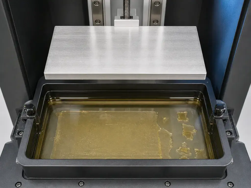
PETG 3D printing problems: manage trade-offs, not universal settings
PETG troubleshooting usually involves balancing competing outcomes rather than applying one setting sequence. PETG is prone to stringing and may bridge or handle overhangs less effectively than PLA in comparable situations. Prusa also describes cooling as a contextual trade-off: more cooling can improve detail and reduce some stringing, while reduced cooling may be relevant when toughness is the priority. [8] Adhesion needs similar context because PETG can adhere too strongly to some build surfaces; use the printer and surface manufacturer’s preparation guidance.
Prusa’s PETG profile is one manufacturer-specific example: 230 °C for the first layer and 240 °C for other layers, with a bed at 85 °C for the first layer and 90 °C for other layers. [8] These are Prusa profile values, not universal PETG settings. No reliable universal figure exists because nozzle design, enclosure conditions, build surface, filament formulation, and intended part properties vary.
For moisture and storage, use the filament supplier’s instructions rather than diagnosing moisture solely from surface appearance. Polymaker lists drying PolyLite PETG at 65 °C for 6 hours only if the material has absorbed moisture. [9] That instruction is vendor- and material-specific, not a universal PETG drying rule. Record the spool identity, storage history, active profile, and tested symptom before making a controlled comparison.
How to judge whether a change worked: controlled comparisons, not accuracy claims
A useful troubleshooting comparison holds the evidence as steady as practical: use the same model, orientation, material, active profile, environment, and inspection method before and after a single change. Photograph the same features, record the failure height or location, and compare like with like. A successful cube is evidence about that cube under those conditions; it does not establish printer-wide accuracy, part strength, or long-term reliability.
Formal test artefacts can support structured evaluation. ISO/ASTM 52902:2023, Edition 2, is a 40-page International Standard published in August 2023 that addresses test artefacts for geometric capability assessment. It also states that it does not discuss a specific manufacturing procedure or machine settings for producing a test piece. [2] A small repeatable model remains useful for isolating a visible symptom, but should not be presented as a universal accuracy test.
Metrology terms help prevent overclaiming. In the International Vocabulary of Metrology (VIM), measurement accuracy is the closeness of agreement between a measured quantity value and a true quantity value; it is not itself a quantity that can simply be assigned to a printer. Measurement trueness concerns the average of infinitely many replicate measurements relative to a reference value, while repeatability is measurement precision under repeatability conditions. [3] In practical terms, parts can repeatedly measure alike without matching the intended reference, or one part can match once without proving consistent performance across repeats.
Current research context: automated fault detection is not a substitute for diagnosis
Camera, sensor, and multisensor approaches to fault detection remain active research areas in material-extrusion printing. A 2022 Sensors study described a low-cost multisensor data-acquisition system for fault detection in fused deposition modelling. [24] Such systems can extend documentation and flag a possible anomaly, but they do not establish the cause of a visible defect on their own. File preparation, material condition, motion, thermal behavior, and environmental factors still require controlled inspection.
When troubleshooting has limits: stop points and escalation
Stop routine troubleshooting and escalate when there is mechanical damage, recurring collisions, persistent abnormal noise, repeated resin-vat failures, or suspected electrical, heater, sensor, or thermal-control faults. Do not continue comparison prints to “work through” unexplained motion or a suspected machine fault.
The authority stack is the exact printer manual, material TDS, and resin SDS. For a platform-empty resin failure with cured material on the vat film, stop the print and follow the documented procedure before attempting another job. [20] Resin safety guidance and the SDS govern protective measures and handling requirements. [18]
Practical takeaway
Treat each failed print as a sequence of evidence: identify the failure stage, inspect the model and sliced preview, preserve the failed part or photographs, and begin with the lowest-risk check.
Effective 3d print troubleshooting is a controlled loop: stage the symptom, inspect the simplest cause classes first, make one change, verify the result with the same comparison, and escalate when evidence points to debris, collisions, abnormal noise, unsafe resin conditions, or suspected machine faults.
FAQ
Use these answers to select a safe first inspection and keep comparisons controlled. They do not replace the exact printer manual, material TDS, or resin SDS.
What is the best first step in 3d print troubleshooting?
Identify the failure stage, then inspect the model and sliced preview before changing hardware or profiles. Check whether planned layers, walls, supports, seams, and travel paths already explain the symptom. Cura’s Preview tools can show generated print and travel paths, while X-ray view can reveal missing or unwanted geometry. [22]
Why are my 3d printing problems not sticking to bed?
Separate immediate first-layer non-adhesion from later corner lift or warping. Inspect visible surface condition, the documented nozzle-to-surface setup, and sliced contact area first. Prusa describes first-layer calibration as setting nozzle-to-surface distance so deposited plastic adheres and is slightly squished. [5] If attachment begins well but corners lift later, part geometry or environmental conditions may be more relevant than initial contact.
What causes 3d printing problems layer shifting?
A true layer shift can follow an obstruction, collision, loose belt, pulley issue, or other motion-system problem. Confirm that the shift is not already present in the sliced preview, then inspect accessible motion components according to the printer documentation. Prusa recommends checking belts, motor pulleys, and free axis movement without obstructions. [6] Stop after collisions or abnormal mechanical behavior.
How can I tell under-extrusion from a slicer or model artifact such as thin walls or missing geometry?
Compare the print with the sliced preview. If a wall or feature is absent in the prepared file, investigate model geometry and thin-feature handling first. If planned paths are present but deposition is sparse or intermittent, inspect material feed, the drive path, profile and nozzle pairing, and possible hotend restriction. Under-extrusion can appear as gaps in or between printed layers. [10] [22]
How do I diagnose periodic Z artifacts versus random extrusion inconsistency?
Periodic Z artifacts recur at similar vertical intervals across different models, suggesting a repeating mechanical or vertical-motion contribution. Random flow inconsistency is more likely to vary with time, filament path, or material delivery. Compare several prints, record where patterns occur, and confirm that the slicer preview does not contain matching geometry changes. Polymaker notes that slicer settings alone will not correct a frame- or rigidity-related Z-wobble issue. [23]
What should I do if a resin print fails and there may be cured debris in the vat?
Stop and do not restart until the vat and platform have been inspected through the documented procedure. Prusa’s SL1 guidance identifies a platform-empty failure with cured resin on the FEP film as a condition requiring prompt attention. [20] Use the protective equipment specified by the printer instructions and SDS, and do not improvise cleaning tools or solvents when the approved method is unknown. [18]
What do accuracy, trueness, and repeatability mean for 3D prints in practical terms?
Accuracy concerns closeness to a true value, trueness concerns the average of repeated measurements relative to a reference, and repeatability concerns agreement under the same operating conditions. They are not interchangeable. One apparently correct part does not prove all three. [3]
Sources
- ISO/ASTM 52900:2021 Additive manufacturing — General principles — Fundamentals and vocabulary — ISO
- ISO/ASTM 52902:2023 Additive manufacturing — Test artefacts — Geometric capability assessment of additive manufacturing systems — ISO
- International Vocabulary of Metrology (VIM), JCGM 200:2012 — BIPM
- FDM Technology and additive manufacturing — Stratasys
- First layer calibration — Prusa Research Knowledge Base
- Layer shifting — Prusa Research Knowledge Base
- Ghosting — Prusa Research Knowledge Base
- PETG — Prusa Research Knowledge Base
- PolyLite PETG — Polymaker
- Under-extrusion — Prusa Research Knowledge Base
- Extrusion stopped mid-print (heat creep) — Prusa Research Knowledge Base
- Clogged nozzle — Prusa Research Knowledge Base
- Extrusion multiplier calibration — Prusa Research Knowledge Base
- Poor bridging — Prusa Research Knowledge Base
- Support material — Prusa Research Knowledge Base
- Non-adherence — Formlabs Support
- Delamination — Formlabs Support
- Safety for Formlabs SLA printers — Formlabs Support
- Troubleshooting issues with parts printed in Alumina 4N Resin — Formlabs Support
- First layer does not stick (SL1/SL1S) — Prusa Research Knowledge Base
- Essential steps before printing — Phrozen Help Center
- Previewing a print in Ultimaker Cura — UltiMaker Support
- Z-axis wobble — Polymaker Wiki
- A Low-Cost Multi-Sensor Data Acquisition System for Fault Detection in Fused Deposition Modelling — PubMed