
Summary
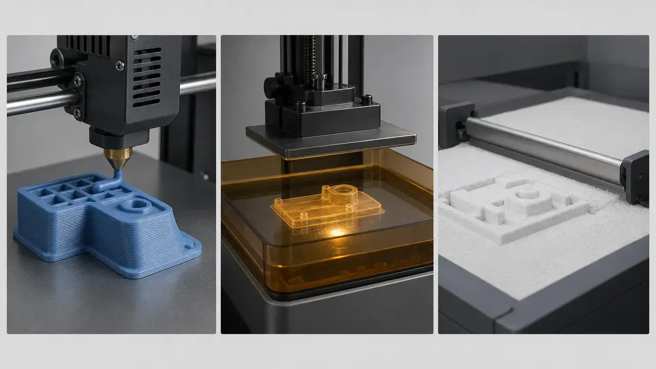
How long does it take to 3D print something? There is no universal number. A small, simple part can be done in minutes, while a larger, denser, or more detailed part can take many hours or stretch into days once setup and finishing are included. The real answer depends on the process family, the model’s geometry, and the slicer settings.
For this article, it helps to separate three different time labels. Slicer-estimated print time is the build time predicted by the slicer for the toolpaths or layers it generates. Machine cycle time is the time the printer spends running the job, including routines the slicer may model imperfectly. Time-to-part is the user-visible total, including setup, support removal, washing, curing, cooling, depowdering, and other delays. That distinction matters because Formlabs says its SLA estimated and calculated print times are based on completing the layers in a job and do not include preprint time. [S10]
Fast estimate checklist
Use this checklist when you need a quick 3D print time estimate without doing a full production analysis.
- Identify the process family first: FDM/FFF, SLA, MSLA, DLP, or SLS.
- Check the part’s height and overall envelope, not just its volume.
- Record the planned layer height or layer thickness.
- Count walls or perimeters and top and bottom solid layers.
- Note infill percentage and infill pattern.
- Review orientation and whether support structures are required.
- Check for multi-material toolchanges, purge moves, or wipe-tower use.
- Add time-to-part steps such as preheat, probing, washing, curing, cooling, depowdering, and cleanup.
Fundamentals and terminology so the time numbers mean the same thing
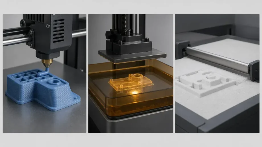
FDM/FFF is the familiar maker term, while standards vocabulary often uses material extrusion for the same process family. ISO/ASTM 52900:2021 is the main terminology anchor for additive manufacturing vocabulary. [S1] For broader taxonomy, NIST describes seven major additive manufacturing families: Binder Jetting, Directed Energy Deposition, Material Extrusion, Material Jetting, Powder Bed Fusion, Sheet Lamination, and Vat Photopolymerization. [S2] This article focuses on FDM/FFF, vat photopolymerization, and SLS because those are the timing cases most readers compare directly. MJF is out of scope here.
What actually determines print time by process family
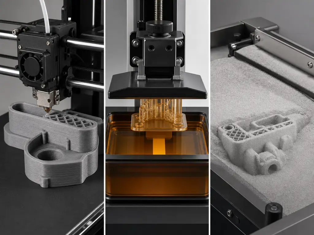
For FDM/FFF, print time is mostly a matter of toolpaths plus motion limits. Perimeters, infill, travels, retractions, seam behavior, and support paths all add motion, and the printer rarely holds its headline speed for long. In slicers, mm/s is a commanded feedrate for specific move types, not a guarantee of sustained average speed. Marlin’s documentation notes that acceleration and jerk affect motion behavior, and that junction deviation controls cornering speed, with smaller values slowing corners. [S9] That is why two jobs with the same nominal speed can finish very differently if one consists of long straight runs and the other is full of short segments, small features, and direction changes.
Vat photopolymerization follows different timing logic. In laser-scanning SLA, a focused laser traces each layer. In DLP, a digital micromirror device projects a mask so a whole layer can be cured at once in a few seconds. [S3] MSLA is another masked, area-exposure resin approach rather than a nozzle-path process, so its timing does not scale the same way as FDM path length. Formlabs lists Form 4 technology as Masked Stereolithography and reports print speed as a vertical rate rather than a path speed. [S11] Even so, resin time is not just part height. Supports, release or peel mechanics, recoating, and printer-specific layer routines still matter, and Formlabs also notes that its SLA print-time estimate excludes preprint time. [S10]
SLS is better understood through build height, thermal cycle, and post-build handling than through a nozzle-style speed number. Formlabs lists the Fuse 1 with a 10 mm/hour build speed, 110 micron layer thickness, and a 165 × 165 × 300 mm build volume. [S13] That helps explain why throughput and single-part turnaround are not the same thing in powder-bed printing: a build can be efficient overall while one part still takes much longer to cool and depowder before it is ready to use.
How to estimate 3D print time before you press Print
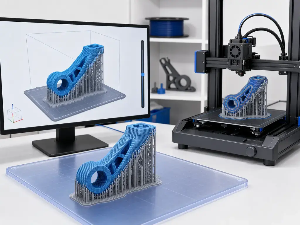
A slicer is the most practical 3D print time calculator because it generates the actual toolpaths or layer sequence your machine will attempt to run. Online calculators based only on part volume or mass can help with rough screening, but they do not know your printer profile, acceleration limits, support strategy, purge behavior, or material profile. A defensible 3D print time estimate comes from slicing the real model with the real machine and material settings.
That estimate still needs context. PrusaSlicer exposes print-time information in both the G-code preview after slicing and the stand-alone G-code viewer. [S7] If your predicted time is repeatedly off, Cura includes a Print Estimation Factor in Printer Settings so you can adjust the prediction when it consistently drifts from actual runtime. [S8] That calibration matters because slicers model the job, but the printer still has to execute it under firmware motion limits and real workflow overhead.
Step-by-step estimate workflow
Use the workflow below when you want a repeatable estimate.
- Import the model and confirm its units and scale.
- Select the exact printer profile, not a generic substitute.
- Select the actual material profile.
- Set nozzle diameter for FDM or layer thickness for resin or SLS.
- Choose layer height, walls or perimeters, and top and bottom solid layers.
- Choose infill percentage and infill pattern.
- Orient the part and generate supports if needed.
- Slice, then record the estimated print time, material use, and any toolchanges, purge structures, or wipe-tower use.
- Add time-to-part steps such as startup routines, cleanup, washing, curing, cooling, depowdering, and operator delay.
Settings that change print time the most
Layer height is one of the biggest levers because it changes how many layers the machine has to produce for a given part height. Lower layer heights often increase print time substantially, but there is no single multiplier that works for every print because acceleration limits, minimum layer-time behavior, cooling, and material flow can take over. Prusa’s infill guidance gives a useful implementation-specific example: with a 0.4 mm nozzle and 0.3 mm layer height, combining infill further does nothing because layers bigger than about 0.32 mm, roughly 80% of nozzle diameter, are not printed in that context. [S4] An illustrative dataset makes the broader point. In NSF PAR dataset rows for an Ultimaker 3 printing PLA, a 0.1 mm layer height at 20% infill took 10:34, while 0.2 mm at 20% infill took 4:00; a 0.1 mm setting at 100% infill took 24:48. [S16] Those rows are examples, not a universal formula, but they show how strongly time can move when layer height and infill change together.
Infill settings matter, but they are not the only structural lever. Prusa says most models can be printed with 10% to 15% infill, rarely need more than 30%, and force rectilinear at 100% infill. The same guide also says strength is mostly defined by the number of perimeters rather than infill. [S4] That is why walls or shell count often improve the speed-versus-strength trade better than simply packing more material into the center. Pattern choice matters too. Prusa’s 15% tree frog comparison reported Gyroid at 1104 minutes and 204 g, Lightning at 840 minutes and 111 g, and Support Cubic at 792 minutes and 152 g. [S5] So “15% infill” is not one fixed time or one fixed material cost.
Supports, orientation, and multi-material behavior can add large hidden penalties. More supports mean more toolpath, more material, and more removal work afterward. Stratasys divides FDM support materials into two broad groups, soluble support and break-away support, which already suggests different removal workflows. [S15] Multi-material printing adds purge and wipe behavior on top of that. Prusa reports that its “no sparse layers” wipe-tower option reduced total print time by 3.16% and wipe-tower filament by 16.17% in its example project set. [S6] For many parts, the fastest orientation in slicer time is not automatically the fastest path to a finished part.
Time-to-part adders you must not forget
FDM/FFF jobs often feel longer than the slicer estimate because the user sees more than path execution. Heating, probing, purge lines, first-layer checks, unloading or loading material, and support removal all sit outside the cleanest version of build time.
What the time number usually excludes
| Process | Often excluded from the displayed time | Why it matters |
|---|---|---|
| FDM/FFF | Startup and post-processing | Heating, probing, purge lines, and cleanup affect real turnaround |
| Resin | Preprint and finishing | Washing and curing are part of making the part usable |
| SLS | Cooling and depowdering | The build can finish long before the part is ready to handle |
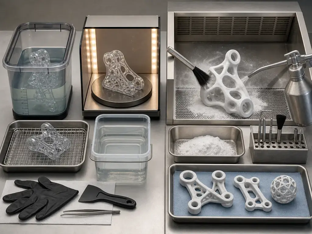
Resin makes the separation especially clear. Formlabs says SLA estimated and calculated print times do not include preprint, and it notes that PreForm versions before 3.27.0 included a preprint estimate that stayed around 20 minutes in versions 3.24.0 through 3.26.2. [S10] After the print itself, more user-visible time follows. Formlabs gives wash times of 5 to 10 minutes and cure times of 1 to 15 minutes, and says parts can go from print to final part in as little as 11 minutes in a best-case example based on 5 minutes of wash, 5 minutes of dry time, and 1 minute of cure. [S12] A resin slicer number is therefore not the same thing as a finished part in your hand.
SLS has the same issue in a different form. In a vendor-supplied Formlabs electrical-connector example, the SLS job is listed as 3 hours 30 minutes of printing plus 6 hours 27 minutes of cooling. [S14] That cooling time is not cosmetic. It is part of the real turnaround before safe handling and depowdering. This is why SLS discussions often sound fast when framed as build throughput, yet much slower when framed as single-part time-to-part.
Speed specs that do not translate directly to finished-part time
A single speed figure can mislead because different processes report different metric families. FDM machines often foreground commanded path speed in mm/s, but Marlin’s motion documentation makes clear that acceleration, jerk, and junction behavior shape how that speed is actually realized in corners and short segments. [S9] Resin and powder-bed systems often foreground vertical build rate instead. Those are not interchangeable numbers, and none of them automatically equals user-visible turnaround.
| Metric family | What it measures | Where it misleads |
|---|---|---|
| Path speed | Motion along toolpaths, often in mm/s | Ignores acceleration, corners, and short segments |
| Vertical build rate | Layer-by-layer rise, often in mm/hour | Ignores preprint, release routines, cooling, and finishing |
| Time-to-part | User-visible total to a usable part | Can still exclude queue delay or downstream manual work |
Formlabs’ Form 4 page is a good example of a different metric family. It lists technology as Masked Stereolithography, a maximum print speed of 100 mm/hour, a typical average of 40 mm/hour, a typical range of 16 to 50 mm/hour depending on material, and a build volume of 20.0 × 12.5 × 21.0 cm, or 5.25 L. [S11] The Fuse 1 SLS spec sheet likewise reports a 10 mm/hour build speed with 110 micron layers and a 165 × 165 × 300 mm build volume. [S13] Those numbers are useful inside their own process families, but they should not be flattened into equivalent mm/s against FDM.
Why slicer estimates are wrong and how to make them more useful
Slicer estimates are models, not stopwatch readings from your exact machine in every condition. They may underweight how acceleration and cornering reduce realized average speed, especially on geometry full of small segments and direction changes. Marlin’s documentation is a good reminder that commanded speed and actual elapsed time are not the same thing. [S9]
Other mismatches come from things the slicer does not fully control: heating, probing, pauses, minimum layer-time behavior, toolchanges, purge routines, and post-processing. Material flow limits can also keep a printer from sustaining nominal speed even on longer moves. That does not make the estimate useless. It means the estimate needs calibration and context.
Cura’s Print Estimation Factor is a practical example of that calibration loop. If your jobs are consistently finishing long or short relative to prediction, slice the part, print it, compare the actual runtime against the estimate, and then adjust the factor where the software allows it. [S8]
Vendor example: the same part can produce very different timelines
A vendor-supplied example is useful when treated carefully. Formlabs compares one electrical connector across three processes and also discloses the machines and core print settings, which makes the example more meaningful than a vague claim that one process is faster. [S14] It is still not an independent ranking, and it should not be read as a universal winner across all parts.
In that comparison, the reported build times were FDM at 2 h 38 min on a Bambu Lab X1 with PLA Basic at 120 microns and 15% infill, SLA at 1 h 3 min on a Form 4 with Grey Resin at 100 microns, and SLS at 3 h 30 min of printing plus 6 h 27 min of cooling on a Fuse 1+ 30W with Nylon 12 Powder at 110 microns. [S14] Formlabs also notes in the same guide that laser SLA generally cures layers more slowly than DLP or MSLA systems that can expose a full cross-section at once. [S14] The lesson is timing logic, not a blanket verdict: the same geometry can produce very different schedules depending on process family and what happens after the build ends.
Practical takeaway — how long does it take to 3D print something?
The most reliable answer to how long does it take to 3D print something is simple: slice the real model with the real printer and material profile, then add the time-to-part steps the machine does not finish on its own. A 3D print time calculator is only as useful as its assumptions. If layer height, walls, infill pattern, supports, orientation, toolchanges, washing, curing, cooling, or depowdering are left unstated, the number is only a rough screen, not a defensible estimate.
FAQ
How long does it take to 3D print something, in general?
There is no single answer. Small and simple parts can finish quickly, while large or detailed parts can take much longer. The useful distinction is between slicer-estimated print time, machine cycle time, and time-to-part. That last category is what users actually feel, because it includes setup and post-processing, not just the build itself.
Why does my printer take longer than the slicer estimate?
Because the slicer predicts the job, while the printer executes it under real motion limits and workflow overhead. Acceleration, jerk, and cornering behavior reduce realized average speed, and startup routines, pauses, minimum layer-time behavior, and toolchanges can all add time that the estimate models imperfectly. [S9]
Is a 3D print time calculator accurate?
It can be useful, but accuracy depends on what kind of calculator you mean. A generic online tool based only on size, mass, or volume is rough. A slicer-based estimate is usually much better because it uses the actual printer profile, material profile, and support plan. Even then, the estimate should be checked against real prints and calibrated if the software supports it.
Is SLA/MSLA/DLP faster than FDM?
Sometimes, but not by one universal rule. Laser-scanning SLA traces layers, while DLP cures a whole layer with a projected mask, and MSLA follows a masked area-exposure approach rather than a nozzle-path approach. That means timing can scale very differently with geometry and part count than it does on FDM. [S3] You also have to include wash and cure when comparing finished-part time.
Does lowering layer height always double the print time?
No. Lower layer height usually increases print time because the job needs more layers, but the multiplier is not fixed. Other limits, including motion behavior, cooling rules, geometry, and infill, can dominate. In illustrative NSF PAR dataset rows for an Ultimaker 3 printing PLA, 0.1 mm at 20% infill took 10:34, 0.2 mm at 20% took 4:00, and 0.1 mm at 100% took 24:48. [S16]
How much longer does multi-color or multi-material printing take?
Usually longer, because every toolchange can add purge motion, extra material, and wipe-structure overhead. The exact penalty depends on how often the model switches materials or colors. Prusa’s wipe-tower documentation shows that purge strategy alone can move both print time and material use, with its no-sparse-layers option reducing total print time by 3.16% in the cited example set. [S6]
How can I reduce print time without ruining strength?
Start with layer height, orientation, walls, and support strategy before pushing infill upward. Prusa’s guidance says most models can be printed at 10% to 15% infill and rarely need more than 30%, while also noting that strength is mostly defined by perimeters rather than infill. [S4] Pattern choice matters too, because different infills at the same nominal percentage can still produce very different print times. [S5]
Sources
- S1. ISO/ASTM 52900:2021, Additive manufacturing — General principles — Fundamentals and vocabulary.
https://www.iso.org/standard/74514.html - S2. NIST SP 1176, Costs and Cost Effectiveness of Additive Manufacturing.
https://nvlpubs.nist.gov/nistpubs/SpecialPublications/NIST.SP.1176.pdf - S3. Taormina et al. (2018), 3D printing processes for photocurable polymeric materials: technologies, materials, and future trends.
https://journals.sagepub.com/doi/10.1177/2280800018764770 - S4. Prusa Knowledge Base, Infill.
https://help.prusa3d.com/article/infill_42 - S5. Prusa Blog, PrusaSlicer 2.5 is here – new perimeter generator, STEP file support, Lightning infill and more!.
https://blog.prusa3d.com/prusaslicer-2-5-is-here-new-perimeter-generator-step-file-support-lightning-infill-and-more_70562/ - S6. Prusa Knowledge Base, Wipe tower.
https://help.prusa3d.com/article/wipe-tower_125010?product=mmu1 - S7. Prusa Knowledge Base, PrusaSlicer G-code viewer.
https://help.prusa3d.com/article/prusaslicer-g-code-viewer_193152?product=mk2-5s - S8. UltiMaker Cura, Releases.
https://github.com/Ultimaker/Cura/releases - S9. Marlin Firmware, Configuring Marlin.
https://marlinfw.org/docs/configuration/configuration.html - S10. Formlabs Support, Understanding SLA print time estimates.
https://formlabs.com/support/Understanding-SLA-print-time-estimates - S11. Formlabs, Compare Formlabs SLA 3D Printers’ Tech Specs.
https://formlabs.com/3d-printers/resin/tech-specs - S12. Formlabs, SLA Post Processing.
https://formlabs.com/global/post-processing/wash-cure/ - S13. Formlabs, Fuse 1 technical specs PDF.
https://formlabs-media.formlabs.com/filer_public/fc/74/fc74250f-5e7c-49a6-8f18-a4ea3bc4572c/fuse-1-fuse-sift-tech-specs.pdf - S14. Formlabs, Guide to Stereolithography (SLA) 3D Printing PDF.
https://formlabs-media.formlabs.com/rs/060-UIG-504/images/WP-EN-guide-to-stereolithography-sla-3d-printing.pdf - S15. Stratasys Support Center, FDM Support Materials.
https://support.stratasys.com/en/Materials/FDM/FDM-Support-Materials - S16. NSF PAR landing for Data in Brief 38 (2021) 107286 print-parameter dataset.
https://par.nsf.gov/servlets/purl/10287870