
Summary
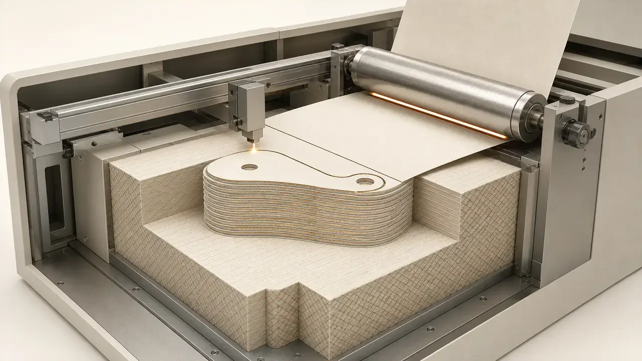
Laminated object manufacturing is a sheet-based additive process that builds a part by bonding layers of material and cutting each layer to shape. In the classic version, the machine laminates adhesive-coated sheets into a stack and trims each cross-section as the build grows. [1] [3]
In ISO/ASTM terminology, the umbrella category is sheet lamination, defined as an “additive manufacturing process in which sheets of material are bonded to form a part,” while material extrusion is a separate category defined as an “additive manufacturing process in which material is selectively dispensed through a nozzle or orifice.” Classic LOM belongs on the sheet-lamination side of that line, not with nozzle-based FDM/FFF systems. It is best understood as a laminate-and-cut workflow with distinct tradeoffs around waste removal, internal cavities, and post-processing. [1] [3]
Definitions and taxonomy
Confusion around laminated object manufacturing often comes from mixing an ISO/ASTM process category with a historically prominent implementation name. ISO/ASTM 52900 defines categories such as sheet lamination and material extrusion. LOM is the older process name most readers mean when they refer to paper-based sheet builds that are laminated and then cut. Some public-facing explainers flatten that distinction by describing sheet lamination as “also known as LOM.” That shorthand is understandable, but it is not the cleanest terminology. [1] [3] [13]
- Sheet lamination — “additive manufacturing process in which sheets of material are bonded to form a part.” [1]
- Material extrusion — “additive manufacturing process in which material is selectively dispensed through a nozzle or orifice.” [1]
- LOM — the historical laminated object manufacturing process built around sequential lamination and cutting of adhesive-coated sheets. [3]
- UAM — an adjacent sheet-lamination route that joins metal sheets or ribbons by ultrasonic welding, often with CNC machining in the workflow. [7]
- FDM vs FFF note — FDM is a Stratasys trademark, so many writers use FFF as the more generic label for the same material-extrusion family. [12]
| Variant | Bonding | Typical feedstock | Main limitation |
|---|---|---|---|
| Classic LOM (bond-then-cut) [3] | Adhesive lamination, then cutting | Paper or polymer sheets | Waste removal and trapped cavities [6] |
| Cut-then-bond LOM/CAM-LEM variant [5] | Cutting before final lamination | Precut sheets, tapes, or laminates | Registration depends more on handling and positioning [5] |
| Paper + selective adhesive (often marketed as SDL) [9] | Adhesive placed selectively rather than across the whole sheet | Paper-based sheets | Different process logic from older glue-everything LOM [9] |
| UAM [7] | Ultrasonic welding, typically with machining | Metal foils or ribbons | Different material and equipment class from classic paper LOM [7] |
That taxonomy matters because not every sheet-based process behaves like classic LOM. SDL-style paper systems place adhesive selectively instead of bonding the whole surrounding field, while UAM replaces adhesive lamination with solid-state ultrasonic welding of metal feedstock. Both sit near LOM in the broader sheet-lamination family, but neither is a simple synonym for the original Helisys-style process. [7] [9]
A brief history: why LOM mattered
Classic LOM was clearly described in 1991 as a process that sequentially laminated and cut 2D cross-sections from adhesive-coated sheets. The architecture in that paper is still the one many engineers picture: a heated roller bonds a new sheet, an X-Y positioning system guides the cut, a CO₂ laser trims the layer, and the surrounding scrap is crosshatched so it can support the build and later be broken away. The same paper reported historic capability figures such as precision below 0.005 in and working-envelope examples of 10 × 13 × 15 in and 20 × 30 × 20 in. These are useful as historical context, not as present-day blanket performance claims. [3]
Today, classic paper-based LOM is better viewed as a reference point for sheet lamination than as the center of current AM discussion. Modern overviews still place LOM alongside UAM within the same family, and peer-reviewed reviews show continuing work on ceramic tapes, preceramic papers, and related laminated workflows. [5] [7]
How the LOM 3D printing process works
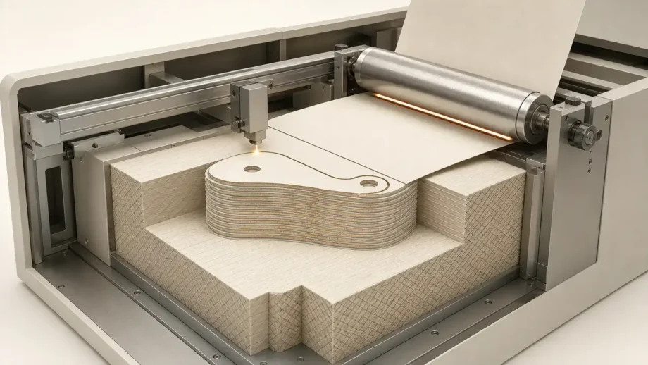
The classic LOM 3D printing process follows a simple loop: laminate a fresh sheet onto the stack, cut the current cross-section, and repeat until the part reaches full height. In the foundational machine description, the build platform moves vertically, a heated roller bonds the incoming sheet, and a CO₂ laser cuts only the top layer. Because the cut follows the layer boundary rather than scanning an entire area, the process was presented as a fast way to build larger, visually oriented models from inexpensive sheet stock. [3]
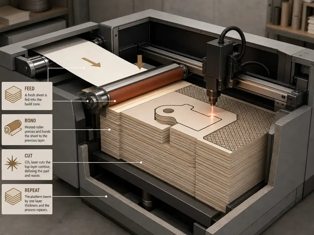
- Export the part from CAD and slice it into layers. [3]
- Feed a sheet into the build position. [3]
- Bond the sheet to the stack with heat, pressure, and adhesive action. [3]
- Cut the layer contour with a laser in classic LOM, or with a knife in broader LOM-family descriptions. [3] [8]
- Crosshatch the surrounding waste so it can be broken away later. [3]
- Repeat the feed-bond-cut cycle layer by layer. [3]
- De-cube the finished block by removing the surrounding waste material. [3] [6]
That surrounding waste is one of the defining features of classic LOM. During the build, it stays around the part and can behave like support for overhangs and undercuts. Under ISO/ASTM terminology, though, support is a structure separate from the part geometry, so LOM’s crosshatched waste block is not the same thing as the separately generated supports common in many extrusion systems. The downside is that the waste coexists with the part until the end, which is why de-cubing and internal cleanup are major practical issues, especially for hollow or enclosed shapes. [1] [3] [6]
After building, the main job is extracting the part from the rectangular block. Some parts need only edge cleanup, while paper-based builds may also be sanded and sealed with paint or lacquer to limit moisture uptake. Broader LOM-family overviews also note that finished parts can be machined or drilled if needed, but the core post-processing burden is still waste removal. [8]
Workflow variants: bond-then-cut vs cut-then-bond
The baseline version of LOM is bond-then-cut, sometimes described as cut-on-the-stack: the fresh sheet is first attached to the build and then its contour is cut. Peer-reviewed review literature also documents the reverse order, cut-then-bond, and the Loughborough overview notes that the cutting and bonding steps can be reversed so the material is cut before being positioned and bonded. In ceramic literature, that cut-then-bond route is also associated with CAM-LEM-style processing. [5] [7]
The choice changes how the build behaves. In bond-then-cut LOM, surrounding waste remains in place during the build, which helps support the part but makes internal waste removal harder later. In cut-then-bond workflows, excess material may be removed before lamination, which can make cavities and delicate outlines more accessible. The tradeoff is that once a layer is shaped before bonding, successful registration depends more heavily on how accurately that pre-cut layer is handled and positioned. [5] [7]
Materials: classic LOM feedstocks and adjacent sheet-lamination variants
Classic LOM uses sheet materials that can be stacked, bonded, and trimmed one layer at a time. Historically, the clearest picture is adhesive-coated paper or polymer laminates, with cutting performed by laser in classic Helisys-style machines and by knife or laser in broader LOM-family descriptions. The material is not deposited bead by bead as in extrusion; it arrives as a preformed sheet that becomes one more layer in the laminated stack. [3] [8]
- Classic LOM feedstocks
- Paper laminates. [3] [8]
- Polymer films or laminates. [8]
- Adhesive-coated sheets. [3] [8]
- Sheet stock intended for laser or knife cutting. [8]
Adjacent sheet-lamination methods widen the material palette, but they should not all be collapsed into “LOM.” In UAM, the feedstock is metal foil or ribbon joined by ultrasonic welding rather than adhesive. Fabrisonic states that a single UAM layer uses foil 0.005-0.010 in thick, and its SonicLayer 7200 brochure lists a 72 × 72 × 36 in machine envelope; these are manufacturer-stated examples, not universal sheet-lamination numbers. In ceramic-based work, the review literature covers cast green tapes, preceramic papers, and CAM-LEM-style rolling conditions up to 80 °C and 0.34-0.68 MPa. The same review also discusses composite-sheet approaches in which the sheet itself carries multiple constituents through the bonding-and-cutting sequence. [5] [10] [11]
- Adjacent variants
- UAM metal foils — manufacturer-stated foil thickness of 0.005-0.010 in and large-envelope examples in the SonicLayer line. [10] [11]
- Ceramic green tapes or preceramic papers — active research feedstocks in laminated ceramic processing. [5]
- Composite-sheet approaches — layered sheets used to carry mixed or functional material systems through the process. [5]
Performance and metrology
- Nominal sheet thickness — the incoming thickness of the raw sheet or tape before bonding and consolidation. [4]
- Actual consolidated layer thickness — the effective layer thickness after bonding, compression, and local deformation in the machine. [4]
- Dimensional accuracy — closeness of the finished dimensions to the intended geometry, which is not the same as precision. [4]
- Precision and repeatability — precision describes how tightly results cluster; repeatability is the ability to reproduce that result under the same conditions. [3] [4]
- Kerf or beam compensation / blade offset — path correction for material removed by a laser or knife so the final contour stays on size. [3] [8]
- Anisotropy — direction-dependent behavior caused by sheet orientation and bondlines through the stack. [5]
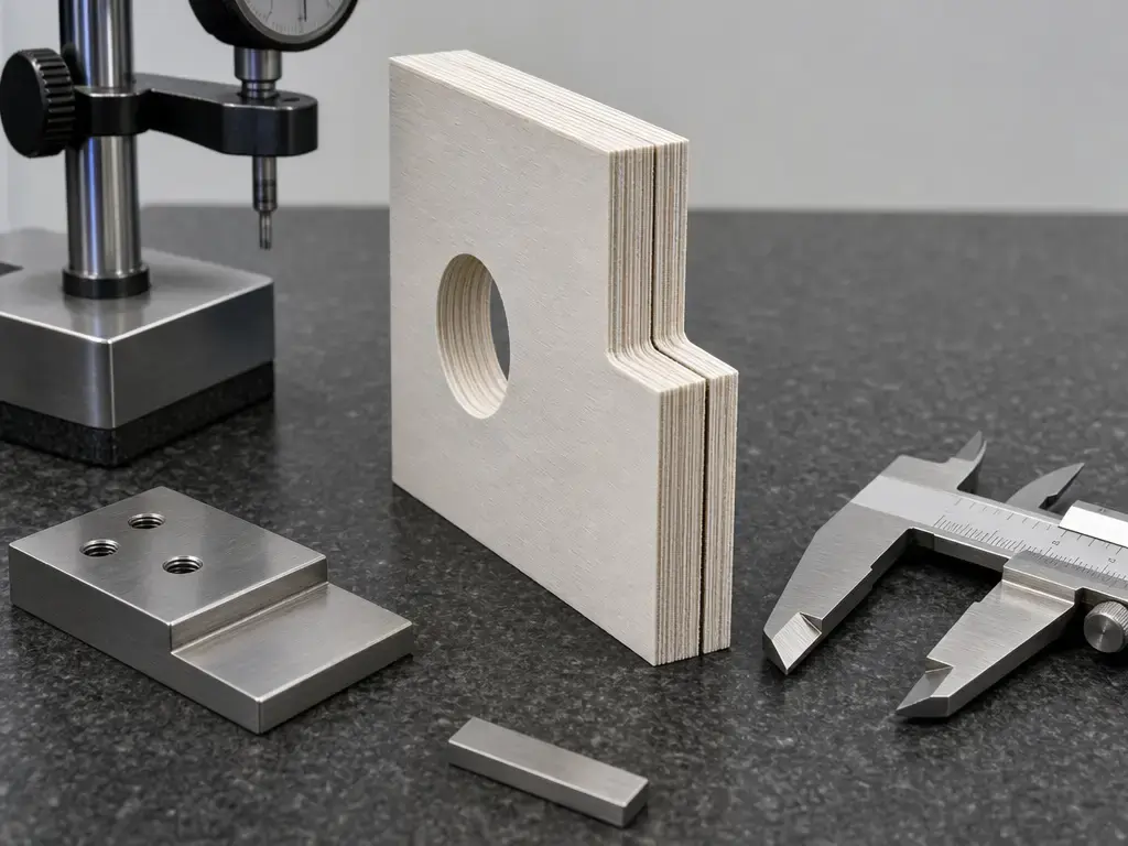
A useful way to think about LOM performance is to separate feedstock, consolidation, and cutting effects instead of asking for one universal accuracy number. Kechagias measured in-plane dimensional accuracy, actual layer thickness, and mean time per layer in a DOE study on a Helisys LOM system. The process parameters tested were nominal layer thickness, heater temperature, platform retract, heater speed, laser speed, feeder speed, and platform speed. That alone is a reminder that layer outcome is tied to machine settings and measurement context, not just to the label “LOM.” [4]
The study is especially helpful on thickness. For actual layer thickness, the ANOVA attributed about 96% of the variation to nominal layer thickness, about 2% to heater speed, and about 1% each to heater temperature and platform retract on that setup. In other words, the incoming sheet thickness dominated the consolidated layer result in that experiment, but it was not the only contributor. Cut quality also matters: Feygin described beam compensation because even a laser treated as a fine tool still removes a finite width of material, so the centerline has to be offset to preserve the intended outline. Add alignment errors, bonding quality, and the practical difficulty of removing internal waste, and dimensional performance quickly becomes geometry- and workflow-dependent. [3] [4] [6]
Material condition matters too. Paper-based laminated parts can absorb moisture unless sealed, which is why moisture sensitivity is best discussed qualitatively here rather than as a single published percentage. Taken together, that is why quoting one number for LOM accuracy is misleading. Historic precision claims, DOE results, and day-to-day dimensional outcomes all refer to specific machines, materials, and test conditions. [4] [8]
Applications: classic LOM and sheet lamination in practice
Classic LOM fits best where fast, low-cost sheet builds matter more than intricate internal freeform geometry. University and industry overviews describe it mainly in visual, aesthetic, and conceptual-prototyping roles, including scale models and appearance-oriented parts. That aligns with the strengths of bonded paper or polymer sheets: they are simple to handle, easy to stack, and well suited to parts that will be extracted, finished, and inspected by hand rather than used as dense structural hardware. [7] [8]
The broader sheet-lamination family is more diverse today. UAM manufacturers position their process around metal parts with embedded electronics, sensors, fiber optics, and other internal features that benefit from solid-state welding plus machining. Fabrisonic also cites build rates of 15 to 30 in³/h, notes a practical height-to-width ratio limit around 0.7-1.0 for tall thin structures, and lists a 72 × 72 × 36 in production-scale envelope for one system. Those are manufacturer claims, but they show how far this neighboring branch has moved beyond paper LOM. At the same time, ceramic-based laminated processing remains active in peer-reviewed research on structural, lightweight, and functional materials. [5] [10] [11]
Advantages and disadvantages of LOM 3D printing
The advantages and disadvantages of LOM 3D printing follow directly from its sheet-based logic. On the plus side, classic LOM uses straightforward sheet feedstock, bonds layers quickly, and lets surrounding material stay in place during the build so the part is naturally supported. The early literature also emphasized that the laser mainly traces perimeters rather than scanning whole cross-sectional areas, which helps explain why LOM was attractive for larger visual models. [3] [8]
The limitations are just as characteristic. Because the part emerges inside a larger laminated block, de-cubing can be laborious and can damage delicate features. Internal cavities, hollow regions, and enclosed voids are harder to clear than in many other AM processes. Paper parts may absorb moisture unless sealed, and general overviews treat classic LOM as better for visual or conceptual work than for structural service. These are central selection criteria for the process. [6] [7] [8]
Pros
- Sheet feedstock is simple to store, feed, and stack. [8]
- Surrounding crosshatched waste can support the part during building. [3]
- Perimeter cutting can be efficient for larger, layered geometries. [3]
- Well suited to visual and appearance-oriented prototypes. [7] [8]
Cons
- Waste removal is labor-intensive in classic bond-then-cut builds. [6]
- Internal waste can trap cavities and limit hollow geometries. [6]
- Paper parts can absorb moisture unless sealed. [8]
- Surface quality depends heavily on cutting and cleanup. [8]
- Classic paper LOM is generally not treated as a structural-use process. [7]
In practice, laminated object manufacturing makes sense when the geometry suits stacked sheets and the post-processing burden is acceptable. It makes less sense when the part depends on clear internal passages, delicate enclosed features, or structural performance better served by other AM routes. [6] [7] [8]
LOM vs FDM/FFF 3D printing differences
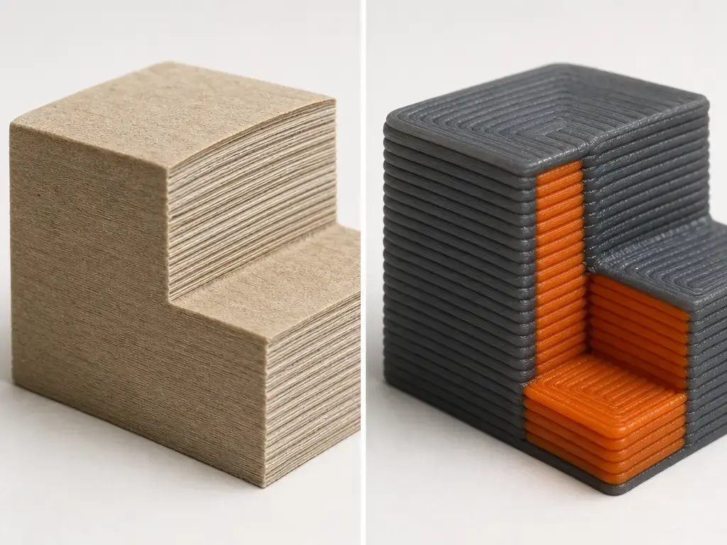
ISO/ASTM gives the cleanest starting point for LOM vs FDM/FFF 3D printing differences. LOM belongs to sheet lamination, where sheets are bonded into a part, while FDM/FFF belongs to material extrusion, where material is dispensed through a nozzle or orifice. Stratasys also states that FDM is a trademark, so using FDM/FFF in comparative writing is a practical neutral shorthand. In practical terms, classic FDM builds by extruding a continuous thermoplastic filament through a heated nozzle, which is physically very different from bonding and cutting sheets. [1] [12] [15]
| Feature | LOM | FDM/FFF | Why it matters |
|---|---|---|---|
| Feedstock | Sheets or laminates [1] [3] | Continuous thermoplastic filament [15] | Changes how material is delivered and stored |
| Bonding mechanism | Adhesive lamination plus contour cutting [3] | Melt extrusion through a nozzle, then solidification [1] [15] | Determines how each layer is formed |
| Supports | Surrounding waste can act like support, but it is not a separately generated support structure [1] [3] | Separate support structures are common in the process family [1] [15] | Affects cleanup and design freedom |
| Internal cavities | Often limited by access for waste removal [6] | Usually easier to route as deposited paths than to excavate from a laminated block [1] [15] | Important for enclosed channels and hollow parts |
| Post-processing | De-cubing, waste removal, edge cleanup, sealing for paper parts if needed [6] [8] | Support removal and surface finishing [1] [15] | Influences labor after printing |
| Typical use | Visual models, appearance models, niche sheet workflows [7] [8] | Broad prototyping and thermoplastic part production [15] | Helps match process to the job |
A useful shorthand is that LOM is a bonded-sheet process with a cutting step inside each layer, while FDM/FFF is a deposited-material process. That difference shapes almost everything downstream, from how overhangs are handled to how internal cavities are cleared after the build. If the geometry is naturally layered and easy to de-cube, LOM can be a sensible fit; if the part depends on freeform internal routing, FDM/FFF is usually easier to work with. [3] [6] [15]
Standards and quality context
ISO/ASTM 52900 is the terminology anchor for this topic. It supplies the standard definitions for sheet lamination, material extrusion, and support, which is why it is the right reference when separating LOM from FDM/FFF or when explaining why LOM’s surrounding waste is not the same as a separately generated support structure. [1]
ISO/ASTM 52920 is broader quality-assurance context, not a LOM-specific approval path. Its catalogue scope states that the document is applicable to the additive manufacturing technologies defined in ISO/ASTM 52900 and defines quality assurance measures along the manufacturing process. That makes it useful background for QA thinking, but not a special certification route for laminated object manufacturing. [2]
Key takeaways: is laminated object manufacturing still relevant?
Laminated object manufacturing remains relevant as the clearest historical reference point for sheet lamination, even if classic paper-based LOM is less visible than it once was. The broader family remains active through neighboring methods such as UAM and through research on ceramic tapes, preceramic papers, and other laminated workflows. For readers comparing AM categories, the key point is simple: classic LOM explains the logic of sheet lamination, while modern sheet-based processes show how that logic continues in newer materials and machine architectures. [5] [7]
FAQ
What is laminated object manufacturing?
Laminated object manufacturing is a sheet-based additive process in which layers are bonded and then cut to shape until a 3D part is complete. In ISO/ASTM terms, it belongs to sheet lamination, while material extrusion is a separate AM category. Classic LOM refers specifically to the historical laminate-and-cut workflow described in the early literature. [1] [3]
How does LOM 3D printing work?
The LOM 3D printing process feeds in a sheet, bonds it to the stack, cuts the current layer contour, crosshatches the surrounding waste, and repeats that cycle until the part reaches full height. The finished build comes out as a block, so post-processing mainly means de-cubing and cleaning away the surrounding waste material. [3] [6]
Is laminated object manufacturing the same as sheet lamination?
Not exactly. Sheet lamination is the ISO/ASTM process category for joining sheets into a part. Laminated object manufacturing is the historical process name most often associated with adhesive-coated sheets that are laminated and cut layer by layer. The terms are closely related, but sheet lamination is broader and also includes methods such as UAM. [1] [3] [7]
What are the main LOM vs FDM/FFF 3D printing differences?
The biggest difference is process family. LOM bonds sheets and cuts each layer, while FDM/FFF extrudes thermoplastic through a heated nozzle. That changes the feedstock, support behavior, internal-cavity handling, and post-processing. It is also good terminology practice to remember that FDM is a Stratasys trademark, while FFF is often used as the generic term. [1] [12] [15]
Bond-then-cut vs cut-then-bond: which is better and why?
Neither is universally better. Bond-then-cut is the classic LOM approach and keeps surrounding waste in place during the build, which helps support the geometry but makes later cleanup harder. Cut-then-bond can improve access to cavities because excess material may be removed before lamination, but it makes layer placement more dependent on accurate positioning and handling. [5] [7]
What limits dimensional accuracy in LOM?
Dimensional accuracy in LOM depends on more than one variable. Kechagias measured in-plane accuracy and actual layer thickness while varying nominal layer thickness, heater temperature, platform retract, heater speed, laser speed, feeder speed, and platform speed. Kerf compensation, alignment, bonding quality, and moisture control also matter, so a single universal accuracy number is not a reliable way to describe the process. [3] [4] [8]
Is laminated object manufacturing still used today?
Yes, but mostly as part of a broader sheet-lamination picture rather than as a dominant paper-prototyping method. Classic LOM still matters as the reference process, while related sheet-lamination routes remain active in areas such as UAM and ceramic-based laminated manufacturing research. That is why the vocabulary is still worth understanding even when the original paper workflow is not the main focus. [5] [7]
Sources
- ISO/ASTM 52900:2021 additive manufacturing terminology excerpt — iTeh preview of EN ISO/ASTM 52900:2021. https://standards.iteh.ai/catalog/standards/cen/4612338f-1a77-455d-905d-178e41f0aae8/en-iso-astm-52900-2021
- ISO/ASTM 52920:2023 catalogue scope page — official ISO catalogue entry. https://www.iso.org/standard/76911.html?browse=tc
- Feygin, M. and Hsieh, B. (1991), Laminated Object Manufacturing (LOM): A Simpler Process — SFF Symposium PDF. https://utw10945.utweb.utexas.edu/Manuscripts/1991/1991-16-Feygin.pdf
- Kechagias, J.D. (2007), Investigation of LOM process quality using design of experiments approach — ResearchGate full-text page for the Rapid Prototyping Journal article. https://www.researchgate.net/publication/235275194_Investigation_of_LOM_process_quality_using_design_of_experiments_approach
- Dermeik, B. and Travitzky, N. (2020), Laminated Object Manufacturing of Ceramic-Based Materials — Wiley Online Library review article. https://advanced.onlinelibrary.wiley.com/doi/full/10.1002/adem.202000256
- Liao, Y.S., Chiu, L.C., and Chiu, Y.Y. (2003), A new approach of online waste removal process for laminated object manufacturing (LOM) — PDF mirror of the Journal of Materials Processing Technology article. https://scholars.lib.ntu.edu.tw/bitstreams/5a10f8f9-e592-422c-95c8-cdadc687e822/download
- Loughborough University AMRG, Sheet Lamination — university technical overview. https://www.lboro.ac.uk/research/amrg/about/the7categoriesofadditivemanufacturing/sheetlamination/
- TWI Global FAQ, What is Laminated Object Manufacturing (LOM)? — industry technical overview. https://www.twi-global.com/technical-knowledge/faqs/what-is-laminated-object-manufacturing-lom
- Mcor Technologies white paper, How Paper-based 3D Printing Works: The Technology and Advantages — SDL versus older LOM framing. https://www.awp1.com/wp-content/uploads/2015/10/MCOR-WPUS-06092013_low.pdf
- Fabrisonic, What is UAM? — manufacturer process page. https://fabrisonic.com/uam/
- Fabrisonic, SonicLayer® 7200 brochure PDF — manufacturer machine-envelope example. https://fabrisonic.com/wp-content/uploads/2024/04/SonicLayer-7200-R4.pdf
- Stratasys, Legal Information — trademark statement including FDM. https://www.stratasys.com/en/legal/legal-information/
- Dassault Systèmes, Sheet Lamination, What is it and how does it work? — example of public-facing terminology conflation. https://akamai.3ds.com/make/guide/process/sheet-lamination
- Xometry, What Is Sheet Lamination in 3D Printing — context overview. https://www.xometry.com/resources/3d-printing/sheet-lamination/
- Stratasys, FDM 3D Printing – Fused Deposition Modeling — official description of filament-based FDM process. https://www.stratasys.com/en/guide-to-3d-printing/technologies-and-materials/fdm-technology/