
Summary
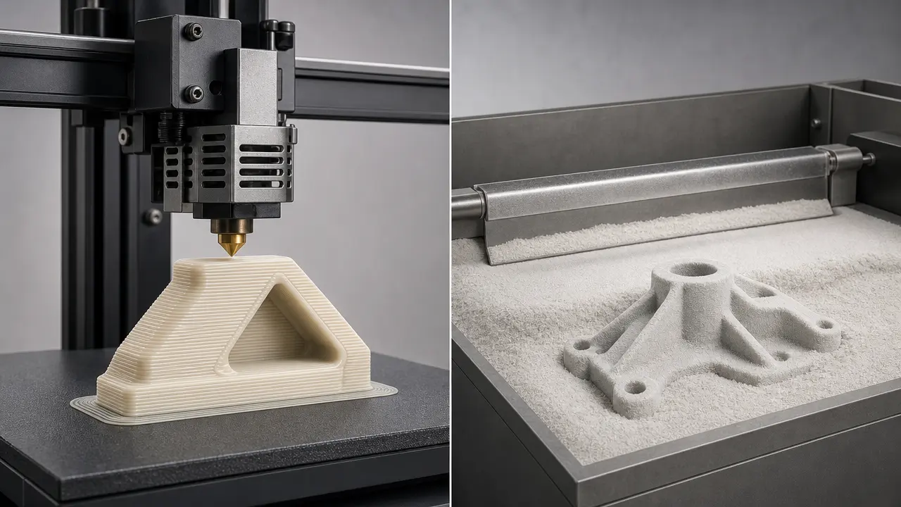
FDM vs SLS is easiest to compare in standards language. ISO/ASTM defines additive manufacturing as the “process of joining materials to make parts from 3D model data, usually layer upon layer,” and the two families here are material extrusion and powder bed fusion. [1] Terminology guidance based on ISO/ASTM recommends using those family names alongside common labels such as FDM/FFF and SLS when that improves recognition. [2] In practice, the choice usually comes down to geometry, material behavior, post-processing labor, and whether you need one large part or a densely packed build. SLS often avoids dedicated support structures, but enclosed features still need drain holes and depowdering access, while FDM more often trades simpler material handling for support planning and removal. [6] [12] [13]
| Aspect | Material extrusion / FDM-FFF | Powder bed fusion / SLS | Practical takeaway |
|---|---|---|---|
| Process family | Material extrusion. [1] | Powder bed fusion. [1] | Compare by standards category first. |
| Geometry support | Usually needs planned supports for many overhangs. [6] | Loose powder supports parts, but enclosed features still need drain holes and powder-removal planning. [12] | SLS favors complex shapes, but only if you can recover and clean them. |
| Typical effort | Orientation, support generation, and support removal. [6] | Cooling, unpacking, depowdering, and cleaning. [13] | Labor shifts, not disappears. |
| Best fit | Large single parts, simpler tools, quick iterations. [6] | Complex nylon parts, nested batches, support-light geometry. [10] [12] | Match the process to geometry and batch size. |
Terminology and brief history
For a standards-first comparison, the formal process families are material extrusion and powder bed fusion. [1] Readers still say fused deposition modeling and selective laser sintering because those labels remain common in industry, but terminology guidance based on ISO/ASTM recommends using the standards category instead of non-standard terms or trademarks when possible, and pairing a market label with its standards family when that improves clarity. [2]
That habit has clear historical roots. Scott Crump’s U.S. patent for the process associated with FDM was published on June 9, 1992, and Carl Deckard’s U.S. patent for selective laser sintering was published on September 5, 1989. [4] [5] Those patent-era names persisted, even though the standards framework is usually better for comparing process principles across machine classes and vendors.
How FDM and SLS work
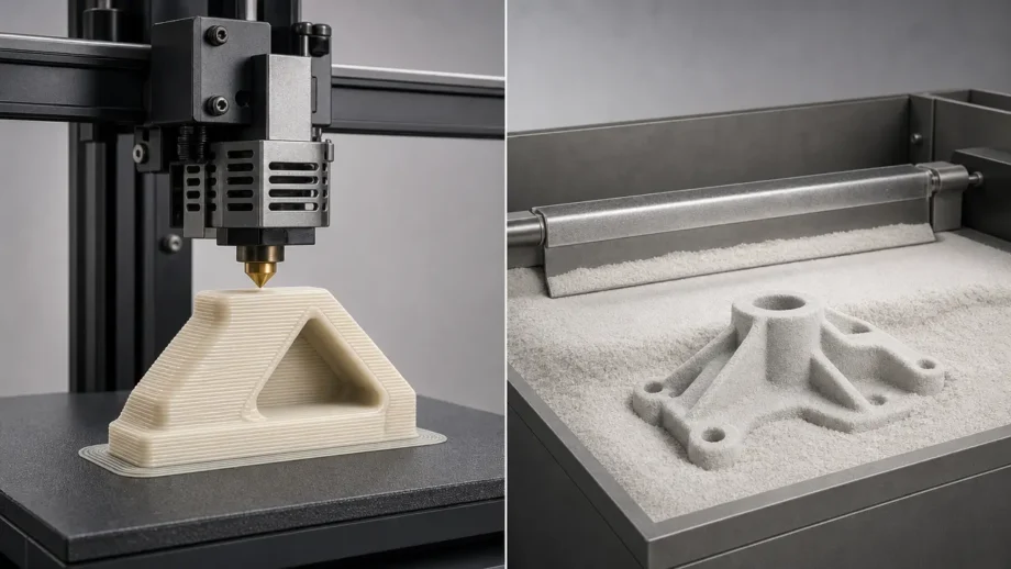
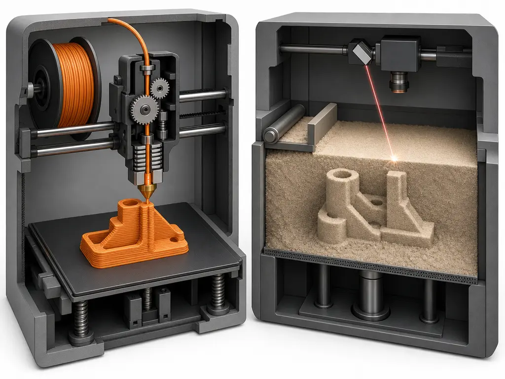
In FDM, a thermoplastic filament is driven into a heated nozzle, softened, and deposited as adjacent roads or beads that define each layer. Each new road bonds to neighboring material and to the layer below, so layer adhesion depends on temperature, bead geometry, and local cooling behavior. Supports are often generated for overhangs, which makes orientation part of the process rather than an afterthought. Industrial design guidance gives a concrete example of how that affects design: recommended minimum wall thickness is generally 4× the layer thickness, with example minimums from 0.508 mm at 0.127 mm layers to 2.54 mm at 0.508 mm layers. [6] Material extrusion also remains relevant for large tooling and housings because one industrial guide lists single-part build size up to 914 × 610 × 914 mm. [6]
In SLS, a thin layer of polymer powder is spread across a heated bed and a laser selectively fuses the regions that will become the part. The surrounding loose powder acts as support, so dedicated support structures are usually unnecessary for many geometries. [12] One current compact industrial example lists 110-micron layers. [9] But powder support does not make geometry unlimited. In Formlabs’ Fuse Series design guide, recommended minimum hole diameter is 1.0 mm, enclosed cavities need drain holes at least 3.5 mm in diameter, and internal surfaces should be reachable for cleaning tools so unsintered powder can actually be removed. [12]
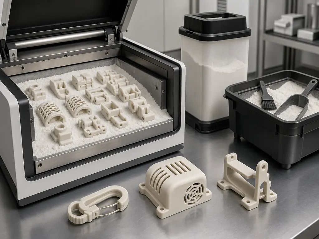
The difference becomes clearest after the last layer is formed. In FDM, the operator usually removes the part from the build plate, removes supports, and finishes any support-contact or bead-texture surfaces that matter. In SLS, the build first cools in the chamber, then parts are unpacked from the powder bed, depowdered, and often media blasted to reach a clean, powder-free surface. [13] That changes the labor model rather than eliminating it. FDM often feels simpler for one large fixture or enclosure, while SLS often becomes more attractive when many smaller parts can share one build volume. [6] [12] [13]
Materials: what each process usually prints
Among plastic 3D printing methods, material extrusion spans a wide range of thermoplastics, from easy-printing desktop filament to industrial engineering polymers. That matters because FDM vs SLS is also a feedstock comparison: filament on one side, polymer powder on the other. A desktop/prosumer PLA example from UltiMaker shows tensile stress at break of 45.5 ± 1.1 MPa in XY, 56.0 ± 1.5 MPa in YZ, and 33.1 ± 2.8 MPa in Z, plus heat deflection temperature at 0.455 MPa of 58.8 ± 0.4 °C. [8] An industrial material-extrusion example, Stratasys ABS-M30, lists heat deflection temperature at 0.455 MPa of 104.4 °C, which is a useful reminder that FDM is not limited to commodity PLA. [7]
SLS usually runs polymer powders, and nylons are common because they process well in a powder bed and often produce durable functional parts. But SLS is not nylon-only. In one industrial SLS material data sheet, EOS PA 2200 Balance lists a melting temperature of 176 °C. [11] In a compact industrial SLS example from Formlabs, Nylon 12 Powder lists printed density of 0.99 g/cc, ultimate tensile strength of 50 MPa, and heat deflection temperatures of 87 °C at 1.8 MPa and 171 °C at 0.45 MPa. [10] These are material examples, not universal values for all SLS parts.
Typical family groupings in plastic printing methods include:
- FDM/FFF: PLA, ABS, PETG, nylon, filled grades, high-temp industrial thermoplastics. [7] [8]
- SLS: PA12, PA11, filled nylon variants. [10] [11]
Performance metrics that matter
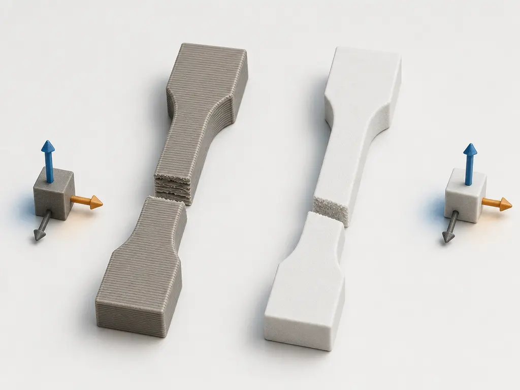
When people compare mechanical strength, the first step is to separate strength from stiffness and label every example by process, material, and orientation. Stratasys states directly that “Parts created using FDM are anisotropic.” [7] In one industrial FDM example, ABS-M30 printed on an F900 at 0.25 mm layer height lists yield strength of 30.8 MPa in XZ and 27.5 MPa in ZX, with break strength of 28.1 MPa and 26.8 MPa respectively. [7] In a desktop material-extrusion PLA example, tensile stress at break ranges from 56.0 ± 1.5 MPa in YZ to 33.1 ± 2.8 MPa in Z. [8] For SLS, Formlabs Nylon 12 Powder lists ultimate tensile strength of 50 MPa on Fuse 1+ test specimens, while EOS PA 2200 Balance at 120 µm layer thickness lists tensile modulus of 1650 MPa in X, Y, and Z, with tensile strength of 48 MPa in X and Y and 42 MPa in Z. [10] [11]
Elongation and orientation sensitivity need their own reading. In material extrusion, layer adhesion is one reason Z-oriented behavior can differ sharply from in-plane behavior, because failure may localize at interlayer boundaries rather than through a more uniform bulk section. Review literature on additively manufactured polymers treats anisotropy as a recurring issue, not an edge case. [3] Desktop PLA illustrates that clearly, and industrial ABS-M30 does too. [7] [8] SLS is often more balanced, but it is not perfectly isotropic. Formlabs Nylon 12 Powder lists elongation at break of 11% in X/Y and 6% in Z, while EOS PA 2200 Balance lists strain at break of 18% in X and Y but 4% in Z. [10] [11]
Heat resistance also has to be read under stated test loads. Industrial FDM ABS-M30 lists HDT at 0.455 MPa of 104.4 °C, while the desktop PLA example lists 58.8 ± 0.4 °C at the same load condition. [7] [8] Formlabs Nylon 12 Powder lists 87 °C at 1.8 MPa and 171 °C at 0.45 MPa, so matched test conditions matter before making cross-process claims. [10] Surface finish needs the same discipline. No reliable figure found here for a universal Ra comparison across directly equivalent FDM and SLS setups, so it is safer to say that surface finish depends on layer strategy, powder particle effects, orientation, and post-processing rather than quote a single ranking.
Workflow and production economics
The workflow difference starts before the machine prints anything. In FDM, the operator usually chooses orientation, decides how much support is acceptable, and checks whether thin walls make sense for the selected layer strategy; one industrial guide recommends minimum wall thickness generally at 4× layer thickness. [6] During the build, common concerns include first-layer stability, support reliability, and whether a tall or narrow part will survive the whole run. In SLS, setup shifts toward powder handling, part packing, and depowder-aware geometry. The Fuse Series design guide recommends at least 5 mm spacing between separate parts for high-quality results, recommends 1.0 mm as a minimum hole diameter, and requires at least two 3.5 mm drain holes for enclosed cavities. [12] A current Fuse Series tech-spec page also lists 110-micron layers, which helps explain why many smaller parts can be nested within one job. [9]
The labor model is different, not absent. FDM often spreads labor across orientation choices, support removal, and local finishing. SLS shifts labor toward cooling, unpacking, depowdering, and managing build utilization across batch production. [13] That is why production cost is hard to reduce to a universal machine-price comparison. No reliable figure found for a process-wide cost-per-part or print-speed winner independent of geometry, nesting density, machine class, material, and post-processing route. Large-format FDM can stay attractive for oversized fixtures because industrial systems can reach 914 × 610 × 914 mm, while SLS often improves economics when many smaller parts share a packed build. [6] [12] [13]
Key production cost drivers include:
- FDM cost drivers: support planning and removal labor; orientation-sensitive failure risk; wall-thickness and sectioning decisions tied to deposition strategy; lower utilization when parts cannot be stacked efficiently; advantages for very large single parts on large-format systems. [6]
- SLS cost drivers: powder handling; cooling delay; depowdering and cleaning labor; drain-hole and access planning for enclosed geometry; better batch economics when many compatible parts fit into one build. [12] [13]
When FDM makes more sense
In FDM printing vs SLS printing, FDM tends to fit better when the job is a large single part, a quick design iteration, or a simple functional tool that does not benefit much from dense batch nesting. Large-format capability is a real differentiator, with one industrial guide listing 914 × 610 × 914 mm as a maximum single-part build size. [6] That matters for fixtures, jigs, guards, and enclosures that would be awkward to segment. FDM also remains practical for concept models and low-cost one-offs when geometry is simple and support removal is easy. The limits still matter: Stratasys states that parts created using FDM are anisotropic, and material choice ranges from desktop PLA at 58.8 ± 0.4 °C HDT to industrial ABS-M30 at 104.4 °C under the same 0.455 MPa condition. [7] [8]
Best-fit FDM cases often include:
- Large fixtures, jigs, and shop aids that benefit from generous build volume. [6]
- Concept models and draft-fit checks where fast iteration matters more than packed batch throughput.
- Simple one-off functional parts with accessible support removal.
- Enclosures, brackets, and guards whose geometry is support-manageable and does not justify powder handling.
- Applications where the selected filament’s directional and thermal limits are understood in advance. [7] [8]
When SLS makes more sense
SLS makes more sense when the goal is a functional polymer part rather than only a quick shape check, especially if nylon-like behavior is a good material fit. In one compact industrial SLS example, Formlabs Nylon 12 Powder lists printed density of 0.99 g/cc, ultimate tensile strength of 50 MPa, and HDT values of 87 °C at 1.8 MPa and 171 °C at 0.45 MPa. [10] In an industrial EOS PA 2200 Balance example at 120 µm layer thickness, tensile modulus is 1650 MPa in X, Y, and Z, while tensile strength is 48 MPa in X and Y and 42 MPa in Z. [11] Those examples help explain why selective laser sintering is often chosen for durable housings, clips, snap-fit features, and lightweight functional parts.
It also makes more sense when geometry benefits from loose-powder support and when batch production matters. A current Fuse Series example uses 110-micron layers, and the powder bed fusion process allows many parts to share one powder bed without dedicated support structures under each one. [9] [12] But support-free only means no generated support structures in many cases; it does not mean constraint-free design. In the Fuse Series SLS design guide, recommended minimum hole diameter is 1.0 mm, enclosed cavities need drain holes at least 3.5 mm across, and internal surfaces should be reachable so cleaning tools can remove trapped powder. [12] The same guide gives minimum integrated-assembly clearance of 0.3 mm for features smaller than 20 mm² and 0.6 mm for larger ones. [12]
Limitations, failure modes, and selection mistakes
Material extrusion tends to fail where the deposited layers become the weak link. Stratasys explicitly notes that parts created using FDM are anisotropic, and the ABS-M30 F900 example shows yield strength of 30.8 MPa in XZ versus 27.5 MPa in ZX, with break strength of 28.1 MPa versus 26.8 MPa. [7] A desktop PLA example shows the same issue even more visibly, with 45.5 ± 1.1 MPa in XY, 56.0 ± 1.5 MPa in YZ, and 33.1 ± 2.8 MPa in Z. [8] In practice, that means cracked layer interfaces, weak snap features in the wrong orientation, and support scars or bead texture even when dimensions are otherwise acceptable.
SLS fails differently. It is often more balanced than FDM, but it is not perfectly isotropic: EOS PA 2200 Balance lists tensile strength of 48 MPa in X and Y versus 42 MPa in Z, while strain at break drops from 18% in X/Y to 4% in Z. [11] Geometry can also fail at the design stage if holes, clearances, or powder-removal paths are ignored. In the Fuse Series design guide, holes under 1.0 mm may close, enclosed cavities need 3.5 mm drain holes, and integrated assemblies need 0.3 or 0.6 mm clearance depending on feature size. [12] A part that looks printable on screen can still be difficult to clean or impossible to free of trapped powder.
A common buyer mistake is to compare unlike metrics. Accuracy vs precision vs resolution is not just wordplay: resolution concerns the smallest increment or feature a process can place, precision concerns repeatability, and accuracy concerns closeness to the intended dimension. Surface finish is also not the same as dimensional fidelity. No reliable figure found here for a universal FDM-versus-SLS accuracy number across machine classes. Another mistake is to compare thermal numbers without matching the test load, since the same Nylon 12 material example ranges from 87 °C at 1.8 MPa to 171 °C at 0.45 MPa. [10]
Current research and market context
Polymer AM is a mature manufacturing field, but the open questions are mostly about optimization rather than basic feasibility. In material extrusion, anisotropy remains both a practical and research concern; industrial documentation still states that parts created using FDM are anisotropic, and review literature continues to treat orientation sensitivity and interlayer behavior as central topics. [7] [3] In SLS, design rules and powder workflow remain active optimization areas. Formlabs’ SLS workflow guidance notes that parts are recovered from unsintered powder after cooling and that unfused powder is reused only with refresh because high-temperature exposure slightly degrades it. [13] That is why polymer AM discussions still center on qualification, powder handling, part orientation, and repeatable post-processing rather than on whether these processes work at all.
Which should you choose?
The best choice follows the job. Start with geometry: if the part is large, fairly simple, and easier to orient than to unpack from powder, FDM may be the better fit, especially because large-format systems can reach 914 × 610 × 914 mm and industrial guidance often starts wall design at about 4× layer thickness. [6] If the part has enclosed channels, packed batches, or many support-troublesome features, SLS often fits better, but the geometry still has to respect design rules such as 1.0 mm minimum hole diameter, 3.5 mm drain holes for enclosed cavities, and clearance for integrated assemblies. [12] Then check the material target: Formlabs Nylon 12 Powder lists 50 MPa ultimate tensile strength and HDT values of 87 °C at 1.8 MPa and 171 °C at 0.45 MPa, while EOS PA 2200 Balance lists 1650 MPa tensile modulus in X, Y, and Z. [10] [11] A current Fuse Series example uses 110-micron layers, which helps frame the scale at which compact SLS systems operate. [9]
- Choose FDM when the part is large, the geometry is support-manageable, the batch is small, and the labor model favors direct part recovery over powder handling. [6]
- Choose SLS when part count is high, batch production and nesting matter, the geometry benefits from powder support, and the design can accommodate hole, clearance, and depowdering rules. [12] [13]
Neither process is universally better. In FDM vs SLS, the better method is the one whose geometry limits, material behavior, labor pattern, and batch logic match the part you actually need to make.
FAQ
What is the difference between FDM and SLS?
FDM is a material extrusion process that deposits softened thermoplastic filament through a nozzle, while SLS is a powder bed fusion process that fuses polymer powder in a bed. [1] In practice, FDM often needs planned supports, while SLS usually avoids dedicated support structures but still requires depowdering and drain-hole planning for enclosed features. [12] [13]
Which is better, FDM or SLS?
Neither is universally better. FDM often fits larger, simpler, or lower-volume parts, while SLS often fits complex geometry and packed builds better. The better choice depends on geometry, material, labor, and batch size. [6] [12]
Is SLS stronger than FDM?
Sometimes, but not as a blanket rule. Formlabs Nylon 12 Powder lists 50 MPa ultimate tensile strength, but FDM results vary strongly by material and orientation, from 56.0 ± 1.5 MPa in one desktop PLA YZ example to 33.1 ± 2.8 MPa in Z. [10] [8] Compare labeled materials and orientations, not process names alone.
Which is cheaper, FDM or SLS?
No reliable figure found for a universal cost winner. FDM can be economical for simple one-offs or very large single parts, while SLS often gets more competitive as nesting density, build utilization, and batch size improve. Cooling, depowdering, support removal, and cleaning labor often matter more than headline machine price. [6] [12] [13]
What materials are used in FDM and SLS?
FDM commonly uses filament-form thermoplastics, from PLA to engineering grades such as ABS-M30. [7] [8] SLS commonly uses polymer powders, especially nylons such as Formlabs Nylon 12 Powder and EOS PA 2200. [10] [11]
Is “powder printing” the same as SLS?
Not exactly. “Powder printing” is informal umbrella language, while SLS is one specific polymer powder-bed process inside powder bed fusion. [1] [2] It is also only support-light in the sense of no dedicated support structures; enclosed cavities still need drain holes and powder-removal access. [12]
Expert: How do build orientation and anisotropy affect qualification, and when does nesting density matter economically?
For qualification, orientation has to match the real load path. Stratasys states that FDM parts are anisotropic, and EOS PA 2200 Balance still shows directional differences in SLS, with 48 MPa tensile strength in X/Y versus 42 MPa in Z and 18% strain at break in X/Y versus 4% in Z. [7] [11] Economically, SLS tends to pull ahead when many compatible parts can be packed into one build and then cleaned efficiently, not when one oversized part dominates the schedule. [6] [12] [13]
Related on 3D Mag
- Metal vs Plastic 3D Printing: Key Differences
- Electron Beam Melting (EBM) in Metal 3D Printing: Key Differences with SLM
- Bambu Lab P1S vs P2S: Key Differences Explained
Sources
- ISO/ASTM 52900:2021, Additive manufacturing — General principles — Fundamentals and vocabulary
- A guideline for 3D printing terminology in biomedical research utilizing ISO/ASTM standards
- Material Anisotropy in Additively Manufactured Polymers and Polymer Composites: A Review
- US5121329A — Apparatus and method for creating three-dimensional objects
- US4863538A — Method and apparatus for producing parts by selective sintering
- Stratasys Direct FDM Design Guide
- Stratasys ABS-M30 Material Data Sheet
- UltiMaker PLA material page
- Tech Specs for the Fuse Series SLS 3D Printers | Formlabs
- Nylon 12 Powder Technical Data Sheet | Formlabs
- PA 2200 Balance | EOS GmbH
- Fuse Series SLS Design Guide | Formlabs
- Selective Laser Sintering (SLS): Complete Guide to SLS 3D Printing | Formlabs