
Summary
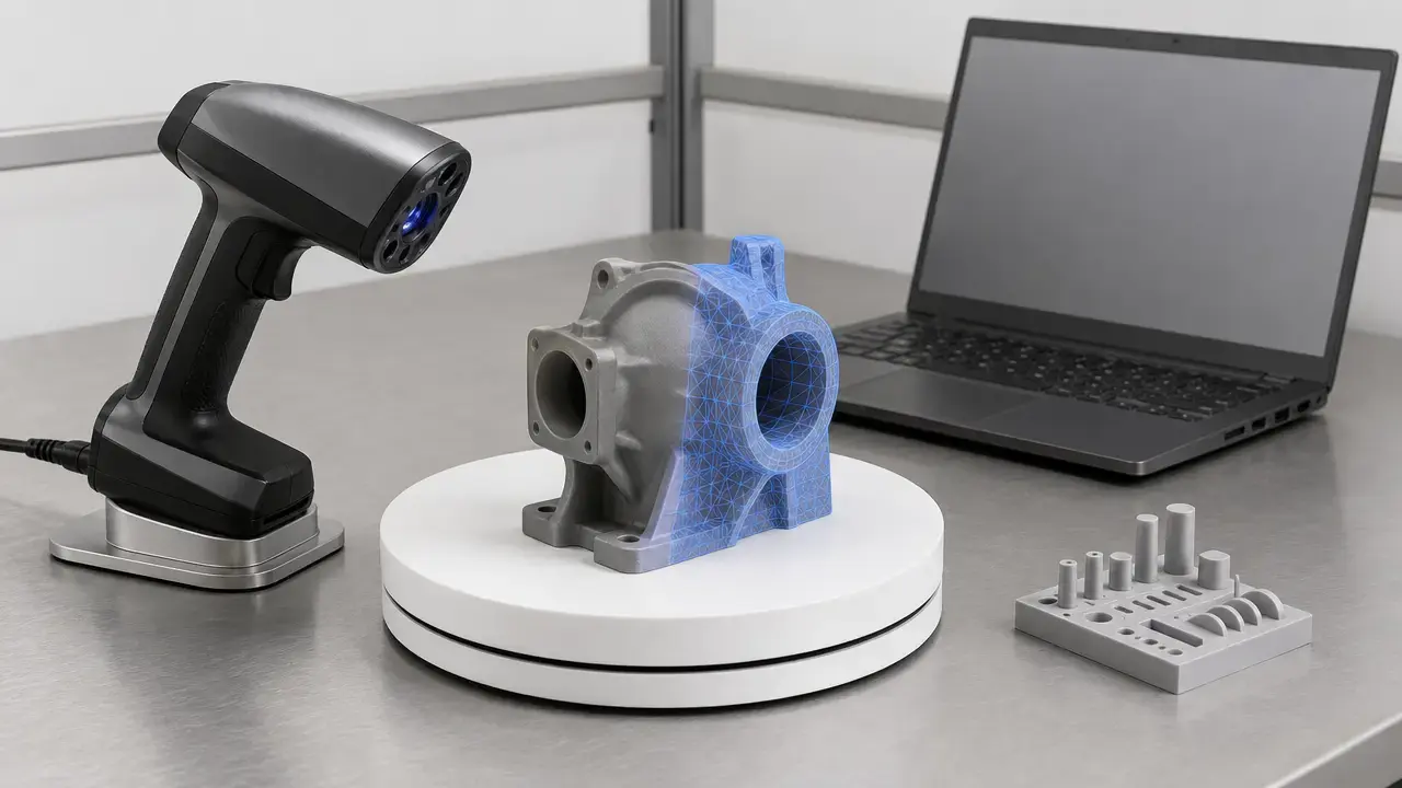
If you want to learn how to scan an object for 3D printing, treat it as a capture-to-cleanup workflow rather than a one-click shortcut. In the terminology used here, additive manufacturing builds physical 3D geometry by successive addition of material, but the scan itself is only captured measurement data, not a finished print file. [1] [18]
That distinction matters because most scans still need alignment, fusion, mesh repair, scale checking, and export decisions before they are ready for slicing. [16] [17] [18] A scan can help you copy shape, preserve a physical object, or start a reverse-engineering job, but exporting it does not automatically make it editable CAD. [11] [18]
Why scanning became a capture step, not the finish line
In restoration, inspection, reverse engineering, and maker workflows, 3D scanning is valuable because it captures shape quickly, not because it removes the rest of the process. [18] The result still has to be interpreted, cleaned, and sometimes rebuilt before it becomes reliable print input or feature-based CAD. [16] [18] Using additive-manufacturing terminology carefully helps avoid the common mistake of treating every digital scan as if it were already a printable or editable final model. [1]
The workflow from object to printable file
A reliable scan-to-print job is a staged process, and each step depends on the quality of the one before it. [7] [8] [10]
- Choose the scanning method
- Prepare the object and environment
- Capture all visible surfaces with overlap
- Align or register multiple scans
- Fuse or convert data into a mesh
- Remove noise and unwanted geometry
- Fill holes only where appropriate
- Make the mesh watertight and oriented
- Check scale against a known dimension
- Export STL, OBJ, or 3MF
- Slice and print a small validation sample
Before you export, you are managing object size, surface behavior, lighting, power, room to move, overlap between views, and the difference between clean capture and later repair work. [8] Real-world scanning also differs from controlled evaluation because sensor configuration, projected patterns, work volume, point density, triangulation angle, and target characteristics all affect results. [7] Many scan packages can track with geometry plus texture and may offer real-time fusion, but that does not remove the need for registration checks, mesh cleanup, or scale verification. [10]
It also helps to separate scanner capability from slicer behavior. [11] [17] A scanner or scan package may export mesh formats such as PLY, STL, or OBJ, and some systems also export 3MF, but your slicer may still ignore attached data or interpret the file in a limited way. [11] [15] [17] That is why a small validation print is worth doing before a full build: it reveals scale mistakes, missing geometry, over-smoothed features, and slicer-side surprises while the job is still cheap to correct. [16] [17]
Know what the scan data actually is
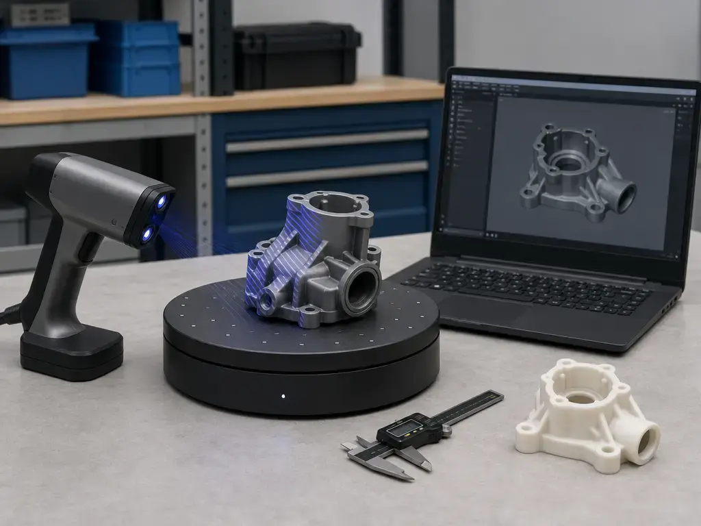
A scan is captured measurement data from the object, not the object itself and not a guarantee of printability. [18] In a typical workflow, you are trying to turn that measurement data into processed geometry that a slicer can interpret reliably. [17] [18]
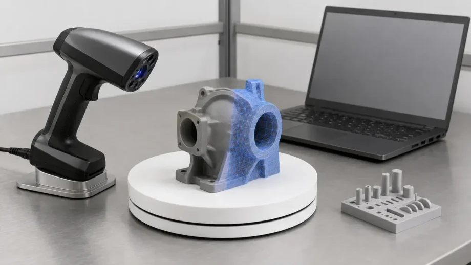
A point cloud is a collection of measured points in 3D space. A mesh is a surfaced model that connects that data into polygons, usually triangles, so software can process a continuous skin. A point cloud is not a mesh, and the mesh is usually what scan-to-print workflows repair and export.
A mesh is still not the same thing as solid CAD. Feature-based CAD models are built from geometric definitions and editable features, while scan meshes are triangle-based surface approximations. [18] Software ecosystems often separate mesh exports from CAD exchange paths, which is why scan tools may export STL, OBJ, or PLY for mesh work while handling STEP/STP, IGES/IGS, or X_T in a different CAD context. [11] If you need editable holes, bosses, planes, or mating faces, you are moving into reverse engineering, not just choosing a different export button. [18]
Choose the capture method for the object
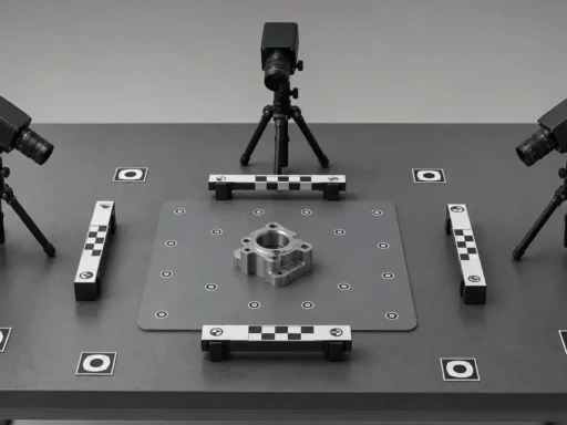
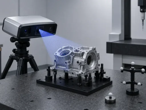
The right method depends on the object’s size, shape, surface behavior, and the scanning conditions you can control. [8] That includes whether the object is matte or reflective, whether you can walk around it, whether a turntable makes sense, and whether scale must be verified later. [8] [9] Manufacturer pages also show why this is not a simple brand-ranking exercise: a structured-light handheld such as Artec Eva, a laser handheld such as the HandySCAN BLACK Elite, and a hybrid white-light/IR handheld such as the EinScan H2 publish different kinds of specifications because they address different capture problems. [13] [14] [15]
| Method | Best for | Strength | Main caution |
|---|---|---|---|
| Structured light [8] [9] | General-purpose capture of small-to-medium objects, especially when you want fast surface coverage | Can capture geometry quickly, often with texture-assisted tracking in software. [10] | Dark, reflective, transparent, translucent, or fuzzy surfaces can be difficult. [9] |
| Laser triangulation [14] | Functional parts and metrology-oriented jobs where dimensional confidence matters | Vendors often publish separate local and volumetric accuracy figures, which is useful for technical work. [14] | Setup, tracking strategy, and whole-object stitching still matter; a strong local spec does not cancel a poor workflow. [7] [14] |
| Photogrammetry [18] | Large visual objects, low-cost capture, and situations where a camera-only workflow is attractive | Accessible and often good for color-rich surfaces. [18] | Lower confidence for small functional parts unless scale is verified and cleanup is expected. [18] |
| Depth camera / phone LiDAR [18] | Quick reference models, rough capture, and convenience-first workflows | Easy entry point with minimal hardware. [18] | Treat as lower-confidence for small functional parts unless you verify scale on the resulting mesh. [18] |
In practice, structured light is a common choice when the object is cooperative and you want fast capture. Laser triangulation is often the more technical path when part geometry and published volumetric behavior matter more than convenience. [13] [14] Photogrammetry and phone capture can still be useful, but for small replacement parts or tight interfaces they are better treated as capture aids than automatic dimensional truth. [18]
Prepare the object and the environment
Preparation is where many avoidable failures begin or disappear. [8] [9] Before scanning, check the object’s size, shape, surface behavior, available lighting, nearby power, and how much room you have to move around the part. [8] If the geometry is simple, the scanned area is too small, or you move too fast, tracking can fail before you even reach the repair stage. [10]
- [ ] Is the object matte enough for optical capture?
- [ ] Can the scanner see all sides?
- [ ] Are there deep recesses or undercuts?
- [ ] Is the object small enough for a turntable?
- [ ] Is scale critical?
- [ ] Will coating or spray alter the object?
- [ ] Are reflective, transparent, dark, or fuzzy surfaces present?
Difficult optical surfaces often need mitigation such as coating, increased sensitivity, or a changed distance and angle. [9] But any added spray or coating can change the measured surface, so it may be a poor choice for delicate, valuable, or tolerance-critical parts. [9] Treat object prep as part of the measurement process, not as a cosmetic step. [8] [9]
Read scanner specs correctly
Keep accuracy, precision, resolution, and registration separate
Scanner specifications are only useful if you keep the categories separate. Accuracy describes closeness to the true value. Precision or repeatability describes consistency from one measurement to the next. Point spacing or point distance describes how densely data is sampled. Mesh resolution describes how fine the surfaced model can be. Volumetric or stitched accuracy describes how error behaves across a longer span of the object rather than at one local patch. Registration error is the mismatch introduced while aligning scans, and alignment drift is the way those small mismatches can accumulate across a longer capture sequence. [7] [13] [14] [15]
Those terms are related, but they are not interchangeable. [7] [15] Lower point distance does not automatically mean better dimensional accuracy, because a dense point set can still be wrong if the surface is difficult, the angle is poor, or the scans were stitched badly. [6] [7] [15] In the same way, a strong single-scan figure is not the same thing as whole-object confidence after multiple passes, alignment, and fusion. [7] [13] [14]
Standards context also matters. VDI/VDE 2634 is part of the standards landscape for optical 3D measuring systems, while NIST explicitly warns that real objects differ from controlled artifacts in sensor configuration, patterns, work volumes, point densities, triangulation angles, and target characteristics. [4] [7] NIST also identifies range, angle of incidence, reflectivity, azimuth angle, method of obtaining the range measurement, and target type as factors that affect range performance. [6] ASTM E3125-17(2025) is a useful counterexample because it addresses medium-range systems operating in at least part of the range from 2 m to 150 m, which is not the same problem as scanning a small object for printing. [5]
How to quote vendor specs without overclaiming
Quote vendor figures exactly, label the model and mode, and do not generalize them across all scanners of that class. [7] [13] [14] [15] For example, Artec Eva publishes up to 0.1 mm 3D accuracy, up to 0.2 mm 3D resolution, up to 0.1 mm + 0.3 mm/m 3D accuracy over distance, and a 0.4 m to 1 m working distance. [13] HandySCAN BLACK Elite publishes 0.025 mm accuracy, 0.020 mm + 0.040 mm/m volumetric accuracy, 0.025 mm measurement resolution, and 1,300,000 measurements/s. [14] EinScan H2 publishes mode-dependent figures: up to 0.05 mm accuracy in white-light mode, up to 0.1 mm in IR mode, 0.2 mm to 3 mm point distance, 1,200,000 points/s at 20 FPS in white-light mode, and 1,060,000 points/s at 20 FPS in IR mode. [15]
Those figures are not saying the same thing, and that is the point. [13] [14] [15] A local accuracy number, a point-distance number, a measurement-rate number, and a volumetric number each describe different behavior. If you collapse them into a simple claim such as “this scanner is accurate to X,” you lose the conditions that make the number meaningful. [7] [14] [15]
Turn scans into a printable mesh
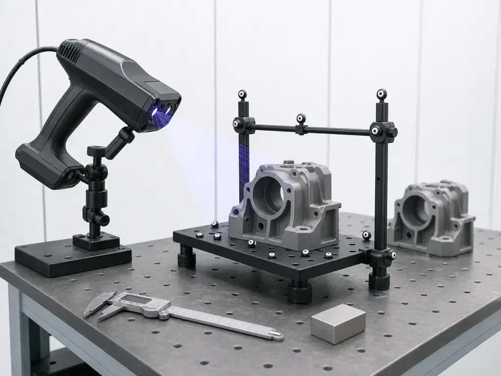
Once you have enough overlapping coverage, the goal is to produce a clean mesh that preserves the geometry you actually need. [10] [16] Some software offers real-time fusion during capture, but post-processing still determines whether the result is printable, overly heavy, or geometrically distorted. [10] A practical cleanup sequence usually includes the following tasks. [16] [20]
- crop unwanted background
- remove floating artifacts
- align scans
- decimate carefully
- fill small holes only where appropriate
- fix normals / orientation
- make watertight
- preserve sharp features where needed
- verify scale before slicing
A watertight mesh is a closed surface that a slicer can interpret as a volume rather than a shell with gaps or contradictory face directions. [16] [20]
Topology repair versus dimensional correction
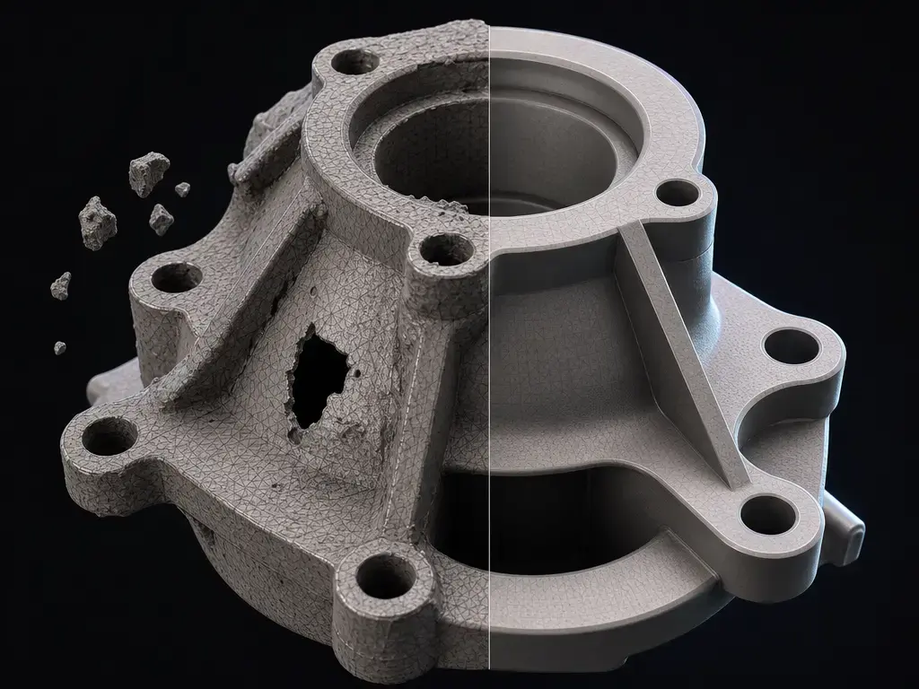
Topology repair is about making the mesh structurally usable. Dimensional correction is about whether the shape is still the right shape after you fix it. Those are not the same task. [16] Autodesk Fusion’s mesh repair tools include Close Holes, Stitch and Remove, Wrap, and Rebuild, and the documentation explicitly notes that Wrap and Rebuild make more significant changes to the mesh body. [16] The same help pages also flag common issues such as mesh not closed, mesh not oriented, and mesh not having positive volume. [16]
That is why smoothing, wrapping, remeshing, and hole filling are not harmless cleanup for mating faces, threads, bosses, sharp edges, or tolerance-critical interfaces. [16] A repair tool can invent triangles where no measurement existed, soften corners you needed, or bridge openings that should have remained open. [16] For decorative replication, that may be acceptable. For functional parts, you often need manual measurement checks after repair, and sometimes the better answer is to stop repairing and rebuild the feature in CAD instead. [16] [18]
If you want a second opinion before slicing, Blender’s 3D Print Toolbox is a bundled analysis add-on that checks for mesh problems that can cause slicing issues. [20]
Pick the right file format and slicer path
File format choice is a workflow decision, not a quality guarantee. [11] [17] Exporting to a different extension does not turn a scan mesh into editable CAD, and it does not guarantee that your slicer will preserve every bit of attached data. [11] [17] [18] For many scan-to-print jobs, the useful question is not “which format is best in the abstract,” but “which format carries the data I need, and how will my slicer treat it?” [17]
| Format | What it carries | Good for | Slicer caveat |
|---|---|---|---|
| STL [12] [17] | Triangle geometry only in most workflows | Broad compatibility and simple mesh handoff | Common and widely accepted, but typically geometry-only. [12] |
| OBJ [12] [17] | Geometry plus linked texture or color files in many workflows | Decorative or textured models | Some slicers ignore material and texture information on import. [17] |
| PLY [11] | Scanner-side mesh or point-style interchange, depending on exporter | Moving data between scan and mesh tools | Import behavior varies by slicer, so confirm before relying on it. [11] |
| 3MF [3] [17] | A richer additive-manufacturing package than STL | Modern print workflows and project-style handoff | Preferred in PrusaSlicer, but behavior still depends on the toolchain. [17] |
| AMF [2] [17] | Standards-based additive-manufacturing format | Standards-aware AM exchange | Supported in PrusaSlicer, but 3MF is suggested there instead. [17] |
| STEP [11] [17] | CAD geometry for reverse-engineering paths | Rebuilt CAD workflows | Triangulated on import in PrusaSlicer, so it is not the default scan-mesh route. [17] |
The scanner side and slicer side are different systems. [11] [17] Artec Studio’s scan and mesh exports include formats such as PLY, STL, OBJ, WRL, X, SCAN, plyVC, and OBC, while its CAD-related contexts include STEP/STP, IGES/IGS, and X_T. [11] The 3MF Consortium now lists 3MF with ISO/IEC 25422:2025 standards status, which is part of why 3MF is often treated as the richer additive-manufacturing option in current software. [3]
When a repaired mesh is enough — and when it is not
A simple decision rule for direct mesh printing vs scan-to-CAD
Use the mesh directly when the geometry only needs to look right and print as a shape. [16] [18] Move toward scan-to-CAD when the geometry has to function like a designed part with controlled interfaces. [18]
- Direct mesh printing may be enough for figurines, sculpture, decorative replication, and some visual reference parts. [18]
- Rebuild in CAD when the part has mating faces, holes, bosses, threads, planar fits, or tolerance-critical interfaces. [18]
- If the part must function as a replacement component, treat scan-to-CAD as the likely next step. [18]
Repair tools can fix closure and orientation problems while still changing the underlying shape, which is why direct mesh printing and CAD reconstruction are separate choices, not just separate export formats. [16] [18] Slicers reinforce that separation: PrusaSlicer prefers 3MF, triangulates STEP on import, and ignores OBJ material or texture information on import. [17] For a universal tolerance threshold that tells you when a scan is “good enough” for all replacement parts, no reliable figure found. [18]
Common failure modes and how to avoid them
Many failures start at the surface. [6] [9] Black, reflective, transparent, translucent, fuzzy, and loosely structured surfaces are difficult for optical scanners because they absorb, scatter, pass through, or otherwise distort the projected light pattern. [9] Deep recesses, undercuts, and occluded regions create a different problem: the scanner cannot measure what it cannot see, so you need more viewpoints, reorientation, or a different method. [8] [18] If you use spray or coating as a workaround, remember that it can leave residue, add thickness, and alter the measured object. [9]
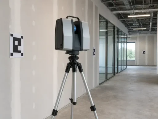
Tracking and alignment failures are common on simple, feature-poor objects or when the scanned area is too small or the scanner is moved too fast. [10] Motion during capture can also break registration, and small alignment errors can accumulate into drift across a longer object or session. [7] [10]
Downstream failures usually appear as wrong scale, missing patches, heavy meshes, over-smoothed detail, or slicer confusion. [16] [17] [20] Wrong scale can come from unit mistakes, bad reference assumptions, or unreliable capture that was never checked against a known dimension. [17] [18] Heavy polygon counts can make cleanup and slicing slower without improving the dimensions you care about. [10] Over-smoothing, wrap operations, and aggressive hole filling can erase sharp features or create geometry that was never measured. [16] A dense point-distance or point-rate figure should not be mistaken for guaranteed part accuracy; even the EinScan H2’s published 0.2 mm to 3 mm point distance is a mode-dependent sampling spec, not a universal promise about finished-part fit. [15]
Key takeaways
- For how to scan an object for 3D printing, the simplest rule is to treat scanning as measurement capture first and print preparation second. [1] [18]
- Choose the method around the object, not marketing categories, and read every spec in the context of mode, setup, and whole-workflow risk. [7] [15]
- Repair only what you understand, because hole filling, wrapping, and smoothing can change geometry as well as topology. [16]
- Verify scale against a known dimension before slicing, especially for phone, photogrammetry, or replacement-part work. [17] [18]
- Pick the export path your slicer actually handles well; in at least one major slicer, 3MF is preferred, but file behavior still depends on software. [17]
FAQ
How to scan an object for 3D printing if I only have a phone?
Use a phone-based photogrammetry or depth-capture workflow as an accessible starting point, but expect cleanup and verify scale before trusting the result for printing. [18] Capture the object from many overlapping angles, avoid motion blur, and compare the finished mesh against at least one known dimension before exporting or slicing. [18] For small functional parts, treat phone capture as lower-confidence than dedicated scanning unless the final mesh checks out dimensionally. [18]
How to 3D scan an object and turn it into an STL file?
Capture overlapping views, align the scans, fuse them into a mesh, remove noise, fix orientation issues, close only the holes that should be closed, verify scale, and then export to STL. [10] [16] Remember that STL is typically geometry-only, so it is a common handoff format for printing but not a color-preserving or CAD-editable format. [12] [17] After export, slice a small test piece before committing to the full print. [17]
Why is my scan the wrong size?
Wrong size usually comes from unit mismatches, unverified scale, or errors introduced during capture and alignment. [17] [18] Phone capture and photogrammetry especially need reference-based scale checks, and even dedicated scanners should be validated against a known dimension before printing a functional part. [15] [18] If the model also had repair or wrap operations applied, confirm that the geometry itself was not changed during cleanup. [16]
Is scanning for 3D printing accurate enough for replacement parts?
Sometimes, but only conditionally. [7] [18] Decorative covers, ergonomic shapes, or noncritical reference parts may print directly from a repaired mesh, while functional replacements often need CAD reconstruction and manual measurement checks. [16] [18] Local scanner numbers and whole-part behavior are different things, so a good single-scan figure does not automatically prove that the full stitched part will fit correctly. [7] [13] [14]
When should I use scan-to-CAD instead of printing the mesh directly?
Use scan-to-CAD when the part has planes, holes, bosses, threads, or mating faces that need to behave like designed geometry rather than a captured surface. [18] That is especially true for replacement parts, assemblies, or anything tolerance-critical. [18] Exporting the mesh as STEP is not the same as rebuilding it as CAD, and slicers may triangulate STEP on import anyway, which shows that scan-to-CAD is a separate workflow decision. [17] [18]
What do alignment drift and registration error mean in a scan-to-print workflow?
Registration error is the mismatch introduced when separate scans or frames are aligned to each other. Alignment drift is what happens when those small mismatches accumulate over a longer sequence and distort the final whole-object shape. [7] [10] In practice, you notice them as stretched dimensions, seams that do not agree, or geometry that looks locally fine but globally wrong. [7] This is why overlap, stable tracking, and validation against known dimensions matter so much. [8] [10]
Sources
- ISO/ASTM 52900:2021 — Additive manufacturing — General principles — Fundamentals and vocabulary
- ISO/ASTM 52915:2020 — Specification for additive manufacturing file format (AMF) Version 1.2
- 3MF Consortium — 3MF Specifications
- VDI/VDE 2634 Blatt 1 — Optical 3D measuring systems
- ASTM E3125-17(2025) — Standard Test Method for Evaluating the Point-to-Point Distance Measurement Performance of Spherical Coordinate 3D Imaging Systems in the Medium Range
- NIST TN 1695 — Characterization of the Range Performance of a 3D Imaging System
- NIST — Sources of Errors in Structured Light 3D Scanners
- Artec 3D — How to 3D scan an object with a portable structured-light scanner
- Artec Support — Black, reflective, transparent, etc. surfaces
- Artec Studio 12 Documentation — 3D Scanning at a Glance
- Artec Studio 17 Documentation — Projects, Scans and Models
- Artec Manual Processing Guide
- Artec Eva product specifications
- Creaform HandySCAN 3D — Technical specifications
- EinScan H2 specifications
- Autodesk Fusion Help — Repair a mesh body
- Prusa Knowledge Base — Supported file formats
- Formlabs — How to Choose the Best 3D Scanner to Use With Your 3D Printer
- Blender Manual — 3D Print Toolbox