
Summary + decision aid
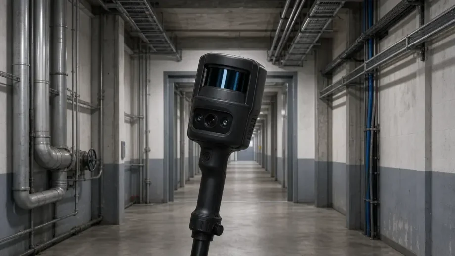
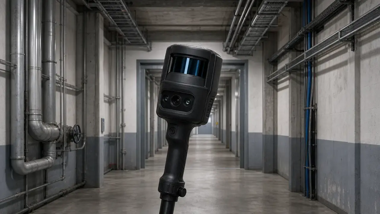
A handheld lidar 3d scanner is a speed-and-coverage tool. Here, that means a professional, hand-carried LiDAR plus SLAM system used while walking through spaces or around large objects, not a tripod scanner, wearable rig, or phone depth feature. Leica’s BLK2GO is a clear class example: its GrandSLAM stack combines LiDAR SLAM, Visual SLAM, and an IMU for real-time mobile capture. [4]
That strength in speed does not mean automatic detail capture or print readiness. The usual first deliverable is a registered point cloud; mesh generation, cleanup, watertight repair, CAD surfacing, and dimensional checking come later. ASTM’s framing for medium-range time-of-flight systems also warns that rated performance can shift in real spaces because geometry, reflectance, ambient lighting, vibration, temperature, humidity, and other field conditions affect results. [1] [2]
Use it when:
- You need fast coverage of interiors, plant rooms, tunnels, mines, or construction progress.
- The goal is context and spatial layout, not micron-level detail.
- You want a rapid first-pass model before tighter verification.
- You need large-object or body-scale reference geometry.
- You will combine the scan with control points, static scans, or manual measurements.
- You need reference geometry for 3D printing, not a guaranteed direct printable mesh.
Don’t use it when:
- Tight tolerances on small parts control the outcome.
- Fine edges, threads, or surface form are the main deliverable.
- The project needs object-metrology-style accuracy from the first capture.
- The environment is low-feature, highly repetitive, or full of motion.
- You need a watertight model without post-processing.
- The scan must be treated as final CAD without geometry checking.
The practical rule is simple: use this class for fast contextual capture and reference geometry, not as a substitute for tight-tolerance object metrology or as proof that a scan mesh is ready to print. [12] [13]
Taxonomy + definitions
The category boundary matters because “LiDAR scanner” can refer to several different tools with very different tolerances, workflows, and outputs. Here, adjacent classes are included only to show where they outperform handheld SLAM LiDAR. A wearable system such as NavVis VLX 3 belongs to the broader mobile mapping family, but it is not handheld; NavVis lists it as a wearable device with a weight of 8.5 kg. [8]
The glossary below sets the vocabulary for the rest of the article so the later sections can stay concise. [8] [14] [17]
Handheld vs wearable vs TLS vs metrology vs phone LiDAR: what we mean in this article
Handheld LiDAR + SLAM — a professional, hand-carried system used while walking through a space or around a large object. It measures range and estimates the scanner path at the same time. [4]
Wearable mobile mapping — a body-worn capture system based on similar mapping logic but with different ergonomics, weight, and workflow. NavVis VLX 3 is one example and is listed at 8.5 kg. [8]
Static TLS — a tripod-based terrestrial laser scanner used from fixed stations for controlled, high-detail scene capture.
Metrology handheld laser-line / structured-light — an object-scanning class aimed at inspection and reverse engineering, with much tighter standards and tolerance language. ISO 10360-13:2021 exists for optical 3D coordinate measuring systems. [14]
Smartphone LiDAR / AR depth — consumer depth capture used for bounded scene reconstruction. Apple documents LiDAR depth for creating a polygonal scene mesh, not as a survey-grade accuracy standard. [17]
LiDAR — in this article, laser-based time-of-flight ranging. [2]
SLAM — the method that estimates the scanner path while geometry is being collected.
Point cloud — a set of measured 3D points, sometimes with attributes such as color or intensity.
Mesh — a connected surface representation made from facets or polygons. [20]
Relative accuracy — how well geometry fits together internally inside a scan or project.
Absolute accuracy — how well the scan aligns to real-world coordinates or control points.
Smartphone LiDAR stays bounded in this article. It can reconstruct a polygonal scene mesh, but it is not treated here as a substitute for professional handheld SLAM LiDAR in survey-like workflows. [17]
What is a handheld LiDAR 3D scanner?
A handheld LiDAR 3D scanner is a mobile capture tool carried through a scene while it records range and estimates its own path. If you ask, “what is a handheld lidar 3d scanner,” the practical answer is a walking-capture system that can produce a usable spatial record without a tripod at every station. In the professional class, the intended output starts as a point cloud, not finished CAD or an automatically printable mesh. [4] [3] [20]
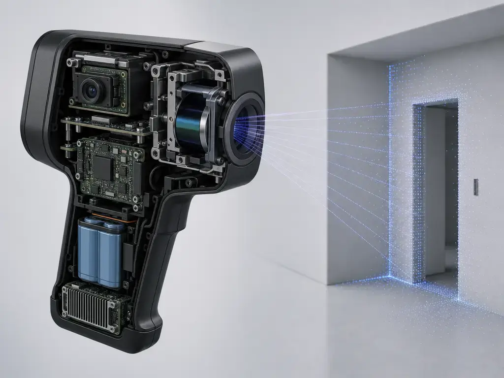
The core workflow is continuous ranging plus continuous path estimation. The sensor records time-of-flight measurements to nearby surfaces, while the tracking stack estimates trajectory from motion and observed geometry. An IMU helps stabilize motion estimation, and some products also use camera data to strengthen tracking. Leica describes BLK2GO’s GrandSLAM as a combination of LiDAR SLAM, Visual SLAM, and an IMU, which is a useful shorthand for how this device class stays aligned while the operator is walking. [4]
Not every handheld system has the same architecture or uses “accuracy” the same way. Leica’s BLK2GO is a continuous walking scanner, BLK2GO PULSE is a shorter-range solid-state handheld design, and GeoSLAM’s ZEB Horizon lists relative accuracy up to 6 mm only when processed in GeoSLAM Connect V2 onwards. That last clause matters because even within the class, a quoted number may depend on processing context rather than raw sensor behavior alone. [5] [7]
How portable LiDAR 3D scanning works
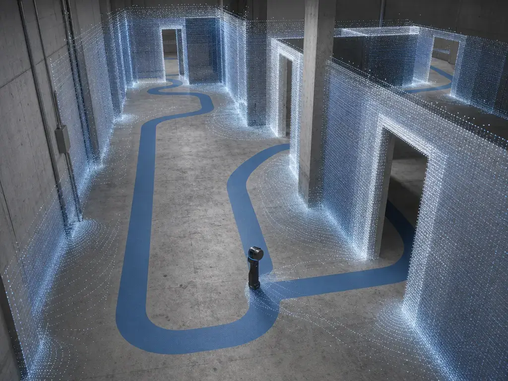
Portable lidar 3d scanning follows a walking-capture pipeline. The operator plans a route, moves through the space, and gives the software enough repeated geometry to keep the trajectory stable. Overlap between passes helps the system compare new measurements with recent ones, and loop closure helps when the path returns near earlier geometry so accumulated drift can be corrected. The usual result is a registered point cloud in one coordinate frame, not a finished surface model. That distinction matters because rated ranging performance and field results are not the same thing; ASTM’s framing for medium-range time-of-flight systems explicitly warns that real surfaces, lighting, vibration, and other environmental factors can change outcomes. [1] [2]
Control points matter when the project needs external truth rather than internal consistency alone. NavVis states that control points provide real-world position information, improve the trajectory estimate, and allow automatic geo-registration and alignment between datasets. [9]
Registration and reconstruction are separate stages. Registration solves how the captured data fit together in space. Reconstruction comes later, when the point cloud may be cleaned, segmented, decimated, meshed, hole-filled, or surfaced for downstream use. A clean walking path helps, but so do practical field choices such as revisiting areas, maintaining overlap, and avoiding routes that give the solver very little distinct geometry to work with. [1] [2]
Typical capture pipeline
- Path planning — choose a route with enough overlap, visibility, and return paths for loop closure.
- Live capture — walk the route while the device records range and tracking data in real time.
- Overlap / looping — revisit areas so the software can compare repeated geometry and stabilize alignment.
- Registration / trajectory solution — solve the scanner path and register the captured data into one frame.
- Cleanup — remove obvious noise, stray points, and unusable sections before downstream work.
- Export — save the registered point cloud for meshing, CAD/BIM work, comparison, or archive use.
Those steps end with a registered point cloud. Meshing, print preparation, and CAD work are later deliverables, not the default raw output of the walk-through itself. [3] [19]
What handheld LiDAR scanners are good at
The main strength of this class is speed, coverage, and context. If the question is “what are handheld lidar 3d scanners good at,” the short answer is large-space capture where walking the job matters more than resolving every small edge. [12]
That makes them useful for interiors, MEP and plant rooms, tunnels and mines, construction as-builts and progress checks, heritage spaces, and other room- or route-scale environments where rapid coverage matters. The Applied Geomatics validation paper frames SLAM handheld mobile mapping as a rapid mapping approach that can be integrated with other static or dynamic measurement techniques, which fits these use cases well. [12]
They can also be useful for large props, mockups, and body-scale reference geometry when the goal is envelope, pose, or spatial relationship rather than tight small-feature fidelity. That is still a reference workflow, not a promise that the first output will behave like an inspection-grade part model. [12] [13]
Hybrid workflows matter here. FARO’s Orbis Premium is an example of a professional product that combines mobile scanning with a stationary Flash mode, reflecting a common field pattern: walk first for coverage, then stop for denser or more controlled detail where needed. In that sense, “good at” means fast contextual capture, not guaranteed fine-detail truth everywhere. [6]
Handheld LiDAR scanner accuracy — what the numbers actually mean
There is no single handheld lidar scanner accuracy number that applies across jobs, because the metric changes with the question being asked. Range noise, local or relative accuracy, absolute or project accuracy, point spacing, and mesh fidelity are different things. The reported value also depends on device class, test context, and output stage. A controlled indoor test says something different from a looped field run, and a point-cloud claim says something different from a later mesh claim. That is why a handheld scan can look clean in one room, drift in a corridor, and change again after registration or meshing. [1] [2] [10]
Manufacturer figures are useful, but they should not be treated as equivalent to independent results. Leica lists BLK2GO at ±3 mm range noise and ±10 mm indoor accuracy on its technology page. Leica’s BLK2GO PULSE lists ±2 cm indoor accuracy in a controlled environment with a 3-minute scan duration, plus ±15 mm real-time range noise and ±5 mm post-processed range noise. GeoSLAM’s ZEB Horizon lists relative accuracy up to 6 mm when processed in GeoSLAM Connect V2 onwards. NavVis lists 5 mm point-cloud accuracy for VLX 3 in a dedicated 500 m² test environment as a local-accuracy statement and separately notes that absolute accuracy depends on environment size and can be controlled via control points. [4] [5] [7] [8]
Independent testing shows the same condition dependence in less controlled form. A 2024 comparison study reported indoor SLAM accuracy around 5 mm and outdoor results from 10 mm to 60 mm depending on conditions. That spread is why “how accurate is a handheld lidar scanner” is really a project question, not a universal product label. ASTM E3125 and ASTM E2938 are useful here only in the right role: they frame derived-point and range-performance terminology for medium-range time-of-flight systems in the 2 m to 150 m class, and E2938 explicitly includes phase-based, pulsed, and chirped systems. They do not function as end-to-end SLAM mapping acceptance standards for mobile reality capture. [10] [1] [2]
The only accuracy number that helps in practice is one tied to a metric, device class, test context, output stage, and source class. [1] [10]
Accuracy terms you’ll see on spec sheets and in studies
Range noise — the spread in repeated distance measurements from the scanner to a surface.
Local / relative accuracy — how well nearby geometry fits together internally before or apart from external control.
Absolute / project accuracy — how well the result matches real-world coordinates or control in the project frame.
Point spacing — the distance between sampled points; it is not the same thing as accuracy.
Mesh fidelity — how closely a reconstructed mesh follows the source geometry after processing.
Accuracy numbers in this article — mapped to metric + context
| Device | Number + metric | Test context | Source class |
|---|---|---|---|
| BLK2GO handheld SLAM LiDAR | ±3 mm range noise; ±10 mm indoor accuracy. [4] | Manufacturer-rated indoor context; output stage not separately stated on the technology page. [4] | Manufacturer |
| BLK2GO PULSE handheld ToF scanner | ±2 cm indoor accuracy; ±15 mm real-time range noise; ±5 mm post-processed range noise. [5] | Controlled indoor environment; 3-minute scan duration for the accuracy statement. [5] | Manufacturer |
| ZEB Horizon handheld SLAM LiDAR | Relative accuracy up to 6 mm. [7] | Processed output in GeoSLAM Connect V2 onwards. [7] | Manufacturer |
| NavVis VLX 3 wearable mobile mapping | 5 mm point-cloud accuracy as a local-accuracy statement. [8] | Dedicated 500 m² test environment; absolute accuracy separately noted as control-point dependent. [8] | Manufacturer |
| Handheld / wearable SLAM LiDAR class | Indoor accuracy around 5 mm; outdoor results 10–60 mm. [10] | Independent 2024 study comparing systems under different conditions. [10] | Independent study |
Limitations and failure modes
The cleanest way to think about failure is to separate two root causes. One group comes from what the laser interacts with in the scene. The other comes from how the system estimates and maintains its own path. That split matters because a scan can look plausible while still being wrong for very different reasons. [1] [2] [11]
Surface / ranging interaction failures (what the laser “sees”)
Specular or highly reflective targets can produce large distance errors in laser-scanning contexts; the 2018 Remote Sensing paper reports that centimeter-scale and even decimeter-scale errors are possible on such surfaces. Glass is another classic trap because it can behave as reflective or transparent depending on incidence angle, which can mislead measurement and later interpretation. ASTM’s caveats also remind you that reflectance, object geometry, particulate matter, and ambient lighting can shift rated performance in real work. In practice, that means glossy, transparent, very dark, or mixed-material scenes can create dropouts, misleading returns, or intensity artifacts that meshing cannot fully repair. [23] [24] [1] [2]
SLAM / trajectory / registration failures (how the scanner “knows where it is”)
Drift happens when the estimated path slowly departs from reality. The risk goes up when the route gives the solver weak or repetitive geometry, when the operator moves too quickly, or when the scan lacks strong loop closure. Mobile scenes with changing objects such as moving people or doors can also disturb alignment. The practical mitigations are procedural: build in overlap, revisit areas for loops, move more deliberately in difficult sections, and add control points when the job needs external truth. NavVis explicitly states that control points improve trajectory estimates and support automatic geo-registration and alignment, which is why they matter so much for absolute project accuracy. The West Point repository record for an IGARSS 2024 paper adds a useful warning: stationary BLK2GO tests reportedly met or exceeded manufacturer specifications at less than 0.020 m RMSE, while mobile tests showed systematic errors. Stable sensor behavior and stable mobile mapping are related, but they are not the same claim. [9] [11]
A good field diagnostic is simple: if repeated features fail to line up, suspect trajectory or registration trouble; if surfaces look patchy, warped, or selectively missing, suspect surface interaction first. Either way, a plausible-looking scan is not the same thing as verified geometry. [11] [23] [24]
Handheld LiDAR vs other 3D scanning technologies
Handheld LiDAR is not a universal replacement for other 3D capture methods. It wins when walking coverage, scale, and context matter. Other tools win when the job is small, tightly toleranced, or calls for a different deliverable. The right comparison is therefore not “best overall,” but “best fit for the geometry, tolerance, and output you actually need.” [14] [15]
| Scanner class | Best at | Weak at | Typical output |
|---|---|---|---|
| Handheld / portable SLAM LiDAR | Fast room-, site-, and route-scale capture with context | Tight small-part tolerances and fine edge fidelity | Registered point cloud; mesh after processing |
| Static TLS | Controlled, high-detail scene capture from fixed stations | Slower coverage; many setups for complex spaces | Dense point cloud; registered survey dataset |
| Handheld laser-line metrology scanner | Object-scale inspection and reverse engineering with tight tolerances | Large-space walking capture | Measurement-grade point cloud; inspection or CAD reference |
| Structured-light object scanner | Small to medium parts and bench-style geometry capture | Very large scenes; shiny or transparent objects can be difficult | Dense point cloud or mesh |
| Smartphone LiDAR / AR depth | Quick bounded scene capture and app-based scene reconstruction | Survey-grade accuracy and full-scope metrology | Depth data and polygonal scene mesh |
The outputs and test regimes differ for a reason. Handheld SLAM LiDAR usually starts as a point cloud for later processing. Metrology scanners use much tighter object-scale accuracy language, and structured-light systems are commonly framed through standards such as ISO 10360-13 or VDI/VDE 2634-style evaluation. NIST also warns that structured-light users can be misled when real use departs from guideline test conditions. The phone row is intentionally limited here to ARKit-style bounded scene reconstruction, where Apple documents polygonal scene meshes rather than a general dimensional-accuracy figure. These classes are not interchangeable by tolerance, scale, or deliverable. [14] [15] [17]
Is a LiDAR scanner good for 3D printing?
Sometimes. A lidar scanner for 3d printing can be useful when the printed result only needs reference geometry, broad shape, or body-scale fit, but not when the part depends on tight dimensional control. The real threshold is required tolerance versus achievable project accuracy. [4] [13]
| Use case | Good fit? | Why | Output check |
|---|---|---|---|
| Direct decorative printable mesh | Sometimes | Large, low-detail forms can tolerate more geometric simplification | Mesh cleanup, hole repair, watertight check |
| Fit-check / ergonomic reference mesh | Often | Envelope and shape matter more than tiny edge detail | Verify scale and obvious holes |
| Reverse-engineered CAD from scan reference | Sometimes | The scan can guide surfacing without being final CAD truth | Compare against known dimensions and datums |
| Small tight-tolerance mechanical parts, threads, sharp edges | No | These features usually exceed handheld SLAM LiDAR’s practical accuracy envelope | Use metrology or structured-light workflows instead |
That table is why “is lidar scanning good for 3d printing” cannot be answered by points per second. Leica’s BLK2GO lists ±10 mm indoor accuracy as a handheld SLAM LiDAR example, while Creaform’s HandySCAN BLACK series cites 0.025 mm accuracy and a volumetric accuracy formula of 0.020 mm + 0.040 mm/m on the metrology side. Those are different device classes, different test framings, and different intended outcomes. If the print depends on tight fit, threads, or sharp edges, handheld SLAM LiDAR is usually the wrong starting point. [4] [13]
Terminology matters as much as geometry. ISO/ASTM 52900:2021 is the additive-manufacturing vocabulary baseline, and the Library of Congress description of STL treats it as a triangular mesh surface format. A scanned mesh is therefore only one stage in the workflow, not proof that the part is printable, watertight, scaled correctly, or dimensionally appropriate for the job. [25] [20]
Workflow — from point cloud to CAD/BIM/mesh/print
Raw handheld LiDAR capture usually begins as a point cloud. E57 and LAS are point-cloud exchange formats, while STL, OBJ, and PLY are mesh-oriented formats used later for visualization, editing, or print preparation. That is a workflow distinction, not a branding distinction. [3] [19] [20] [21] [22]
Formats by stage (point cloud vs mesh vs print)
| Stage | Formats | What they are for | What they are not for |
|---|---|---|---|
| Point cloud capture / exchange | E57 [3], LAS/LAZ [19] | Storing scanned points, attributes, and related imagery; moving point-cloud data between tools | Print-ready geometry |
| Mesh exchange / visualization | PLY [22], OBJ + MTL [21] | Representing reconstructed surfaces for editing, viewing, or later downstream use | Survey control |
| Print preparation | Usually STL [20], sometimes repaired OBJ/PLY [21] [22] | Watertight mesh preparation, scaling, QA, and slicer import | Raw capture truth |
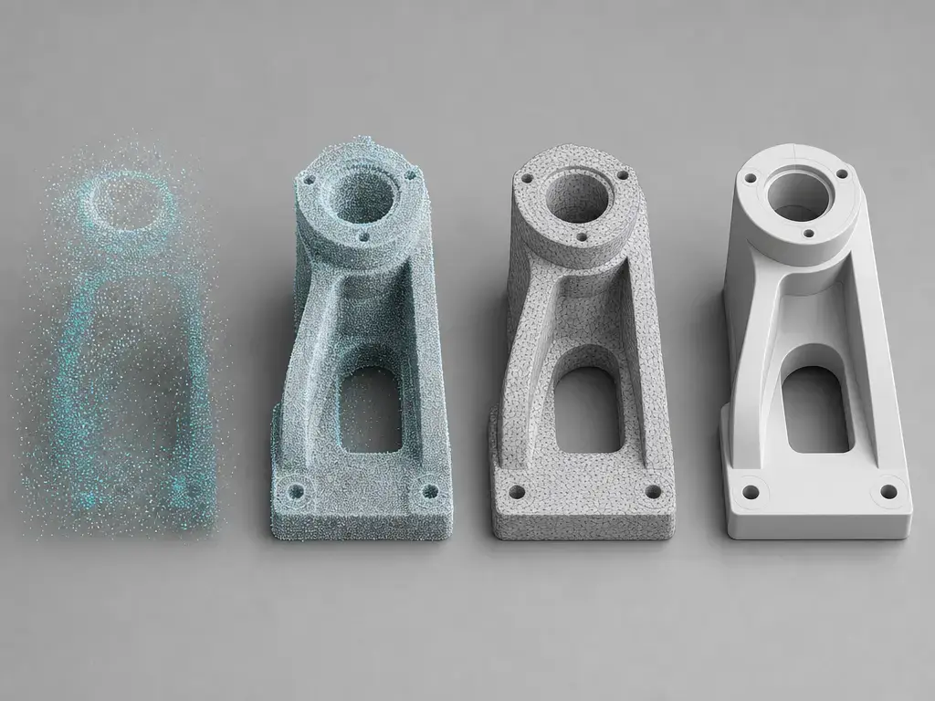
The usual sequence is clean, register, segment, decimate, mesh, hole fill, watertight check, scale/QA, and CAD surfacing if needed. Clean and register first so the data share one frame. Segment the relevant objects or spaces. Decimate only if density gets in the way of downstream processing. Then mesh, repair holes if the use case requires it, and check watertightness before sending anything toward print. If the goal is editable solids or parametric geometry, CAD surfacing comes after those earlier geometric checks, not before them. [3] [20] [21] [22]
Exchange format does not equal deliverable quality. E57 and LAS are not print formats, and STL, OBJ, or PLY are not substitutes for survey control or project verification. [3] [19] [20]
Market + research context
Current products and validation literature point to the same adoption logic: handheld and portable LiDAR are useful because the workflow is fast, mobile, and well suited to contextual coverage. That helps explain why SLAM LiDAR is attractive for building interiors, routes, and mixed field conditions. It does not remove environment dependence, though. The 2024 comparison study still reports indoor accuracy around 5 mm and outdoor results from 10 mm to 60 mm depending on conditions, which is a large enough spread to matter in project planning. [12] [10]
The product direction also points toward hybrid capture rather than one device replacing everything. FARO’s Orbis Premium shows that mobile scanning and short stationary detail capture can coexist in one workflow, while ASTM’s caveats remain relevant because surfaces, geometry, lighting, and motion still separate field results from rated conditions. [6] [1]
Bottom line — when to use a handheld lidar 3d scanner
A handheld lidar 3d scanner is the right tool when coverage, context, and field speed dominate the job. It is the wrong tool when the output has to behave like tight-tolerance object metrology from the start. [4] [13]
Choose handheld SLAM LiDAR for interiors, plant rooms, routes, site context, and reference geometry that will be checked, cleaned, or refined later. Choose metrology or structured-light object scanning when small features, close fits, sharp edges, or inspection-style tolerances control success. The decision is not about whether the scanner looks advanced. It is about whether the device class matches the geometry, tolerance, and deliverable you actually need. [4] [13]
FAQ
What is a handheld LiDAR 3D scanner?
It is a professional, hand-carried LiDAR plus SLAM system used while walking through a scene so the device can collect geometry and estimate its path at the same time. In this class, the normal first output is a point cloud rather than a finished mesh or CAD model. [4] [3]
What are handheld LiDAR 3D scanners good at?
They are good at fast room-, route-, and site-scale capture where context matters more than tiny feature fidelity. That makes them useful for interiors, plant rooms, construction progress, heritage spaces, and other rapid first-pass mapping tasks that may later be combined with more controlled measurements. [12]
How accurate is a handheld LiDAR scanner?
There is no single answer. The number depends on the metric, test context, and output stage. In one 2024 independent comparison, indoor SLAM accuracy was reported around 5 mm, while outdoor results ranged from 10 mm to 60 mm depending on conditions. That is why project accuracy has to be checked against the actual task, not taken from a generic label. [10]
Can you 3D print directly from a LiDAR scan?
Sometimes, but not safely by default. STL is a triangular mesh surface format, so a scan still needs cleanup, hole repair where necessary, watertight checking, and scale/QA before it behaves like a printable model. A point cloud is even earlier in the chain and is not itself a print format. [20] [3]
Is LiDAR scanning good for 3D printing?
It can be good for large, loose-tolerance reference geometry, fit studies, or reverse-engineered CAD starting points. It is usually a poor match for small mechanical parts, threads, and sharp edges. The contrast between handheld SLAM LiDAR figures such as BLK2GO’s ±10 mm indoor accuracy and metrology figures such as HandySCAN’s 0.025 mm accuracy explains why. [4] [13]
Why do handheld LiDAR scans drift, and how can that be reduced?
Drift appears when the trajectory estimate departs from reality, especially if the route lacks strong overlap or loop closure. The practical mitigations are to revisit areas, move more deliberately in difficult sections, and use control points when absolute positioning matters. NavVis explicitly states that control points improve trajectory estimates and support geo-registration and alignment. [9]
What about smartphone LiDAR?
Apple documents LiDAR depth for building a polygonal scene mesh in ARKit, but no reliable figure found in Apple’s official documentation gives a general dimensional-accuracy spec for that workflow. A 2023 field study reported RMS ranges of 0.016–0.035 m and 0.017–0.025 m for two iPhone apps against a ZEB Revo in forest-soil plots, but that is task-specific evidence, not a substitute for professional handheld SLAM LiDAR. Apple’s Class 1 Laser note is a safety classification, not accuracy proof. [17] [16] [18]
Sources
- ASTM E3125-17 / active listing for laser-based scanning time-of-flight 3D imaging systems — https://store.astm.org/e3125-17.html
- ASTM E2938-15(2023) range measurement performance for medium-range time-of-flight systems — https://store.astm.org/standards/e2938
- ASTM E2807-11R19 E57 3D imaging data exchange capability statement — https://store.astm.org/e2807-11r19.html
- Leica BLK2GO Technology page — https://shop.leica-geosystems.com/reality-capture/blk2go/technology
- Leica BLK2GO PULSE tech specs — https://shop.leica-geosystems.com/lat/reality-capture/blk2go-pulse/tech-specs
- FARO Orbis Premium technical sheet PDF — https://media.faro.com/-/media/Project/FARO/FARO/FARO/Resources/2_TECH-SHEET/2024/Orbis-Premium/CMO12127_Techsheet_OrbisPremium_AECO_A4_ENG_Web.pdf
- GeoSLAM ZEB Horizon spec sheet V4 PDF — https://media.faro.com/-/media/Project/FARO/FARO/FARO/New-Product-Images/GeoSLAM/ZEB-Horizon/PDF/Horizon_Spec_Sheet_V4_RT_FARO.pdf
- NavVis VLX 3 specifications — https://www.navvis.com/resources/specifications/navvis-vlx-3
- NavVis control points introduction — https://vlx2.docs.navvis.com/operation/using-the-device/best-practices/control-points/introduction/
- Remote Sensing 2024 study comparing NavVis VLX and Leica BLK2GO — https://www.mdpi.com/2072-4292/16/17/3256
- IGARSS 2024 BLK2GO repository record — https://athena.westpoint.edu/items/b9bf4ec2-e574-4704-aec7-3a491886086d
- Applied Geomatics 2018 validation of SLAM handheld mobile mapping — https://link.springer.com/article/10.1007/s12518-018-0221-7
- Creaform HandySCAN BLACK series brochure PDF — https://www.creaform3d.com/-/media/project/oneweb/oneweb/creaform3d/promotional-documentation/en/handyscan-3d_black-series_brochure_en_hq_20241128.pdf
- ISO 10360-13:2021 optical 3D coordinate measuring systems catalog entry — https://www.iso.org/standard/74957.html
- NIST publication on sources of errors in structured light 3D scanners — https://www.nist.gov/publications/sources-errors-structured-light-3d-scanners
- Frontiers 2023 iPhone LiDAR versus ZEB Revo field-method study PDF — https://www.frontiersin.org/journals/forests-and-global-change/articles/10.3389/ffgc.2023.1224575/pdf
- Apple ARKit scene reconstruction documentation — https://developer.apple.com/documentation/arkit/visualizing-and-interacting-with-a-reconstructed-scene?changes=la&language=objc
- Apple Support iPad Pro LiDAR Class 1 Laser information — https://support.apple.com/guide/ipad/ipad89155f3c/26/ipados/26
- OGC LAS 1.4 community standard listing — https://www.ogc.org/standards/las/
- Library of Congress STL format description — https://www.loc.gov/preservation/digital/formats/fdd/fdd000504.shtml
- Library of Congress OBJ format description — https://www.loc.gov/preservation/digital/formats/fdd/fdd000507.shtml
- Library of Congress PLY family format description — https://www.loc.gov/preservation/digital/formats/fdd/fdd000501.shtml
- Remote Sensing 2018 paper on specular reflection distance errors — https://www.mdpi.com/2072-4292/10/7/1077
- Pattern Recognition Letters article on transparent and specular materials in laser scans — https://www.sciencedirect.com/science/article/pii/S0921889015302736
- ISO/ASTM 52900:2021 additive manufacturing vocabulary catalog entry — https://www.iso.org/standard/74514.html