
Summary
What is a point cloud? It is sampled 3D data: a set of points, usually with X, Y, and Z coordinates, intended to represent part of an object or scene. It is data, not automatically a mesh, a solid, or a parametric CAD model. [1] [11]
Point clouds can come from laser scanning, photo-based reconstruction, and other 3D capture systems, then pass through alignment, cleanup, and export before downstream use. They may also carry RGB color, intensity, normals, scan location, pose, or other metadata, which is where confusion often starts. The same capture can exist as raw scans, a registered project, or an exchange file depending on how it is processed and stored. [1] [12] [14] [16]
What is a point cloud?
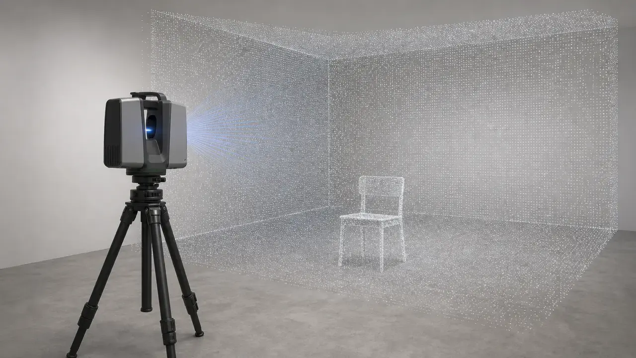
A point cloud is a sampled 3D representation of a surface, usually expressed as XYZ coordinates with optional attributes attached to each point. It is a measurement set rather than a finished geometric object. PCL describes 3D point clouds as points that usually represent the X, Y, and Z geometric coordinates of an underlying sampled surface, and Autodesk defines a point cloud as a set of points intended to represent the external surface of an object. [1] [11]
The phrase point cloud model is common in search, software menus, and everyday use, but it does not imply a finished model in the mesh or CAD sense. A point cloud may also carry RGB color, intensity values, normals, or other attached information, but those additions do not change its basic nature as sampled point data rather than connected geometry. [11] [16] [19]
Some clouds are organized, meaning the software preserves a row-and-column neighborhood structure between points. Others are unorganized, where points are treated as a simple set. That difference affects how software estimates adjacency, computes normals, or resamples the data. In PCD examples, fields can include x, y, z, rgb, and normal components, and an organized cloud may be stored as WIDTH 640 and HEIGHT 480 for 307,200 points, while an unorganized cloud uses HEIGHT 1. [19]
Common data stored per point (optional unless stated otherwise)
- X, Y, Z coordinates. [1]
- RGB color. [16] [19]
- Intensity values. [8] [16]
- Normals. [11] [19]
- Classification or labels in some workflows and formats. [4] [8]
- Timestamp or return information in some capture pipelines. [8]
- Scan pose or project metadata when the format supports it. [11] [16]
Some of that information is truly per point, while some is scan-level or project-level metadata. For example, Autodesk’s E57 export notes describe pose and pointsSize fields, which belong to the scan record rather than to each individual point. In lidar workflows, intensity can also be a required field and is not the same as RGB color. [8] [16]
Point cloud vs mesh
A mesh is a surface structure built from vertices, edges, and faces. A point cloud does not contain that topology. Autodesk defines a mesh as a collection of vertices, edges, and faces, while Autodesk’s 3ds Max help is explicit that point clouds do not contain edges or faces. That is why a point cloud can serve as measured reference data without yet being a directly editable surface model. [11] [18]
Turning point cloud data into a mesh is an interpretive step, not a neutral file conversion. Surface reconstruction methods decide how to connect samples, and that choice can smooth detail, bridge gaps, or extend into areas with weak support. Open3D’s documented methods include alpha shapes, ball pivoting, and Poisson reconstruction, and its Poisson example notes that triangles may be created in low-density areas and may extrapolate beyond measured data. [21]
| Aspect | Point cloud | Mesh | Main risk |
|---|---|---|---|
| Structure | Sampled points only | Vertices, edges, faces | Confusing samples with surface topology |
| Source | Scanner, photogrammetry, or other capture | Usually reconstructed or modeled | Assuming the same data meaning |
| Editing | Strong for measurement, alignment, and reference | Better for surface editing and fabrication prep | Editing can add inferred geometry |
| Gaps/noise | Stays close to measured samples | Often smoothed or filled during reconstruction | Unmeasured areas may be invented |
The distinction in the table follows Autodesk’s definitions of point clouds and meshes and Open3D’s reconstruction caveats. [11] [18] [21]
A mesh is often the better format when you need a continuous surface, simulation boundary, or print-ready shell. A raw point cloud is often the better starting point when you want to preserve what was actually measured before deciding how much geometry to infer. [11] [18] [21]
How a 3D scanner point cloud is created
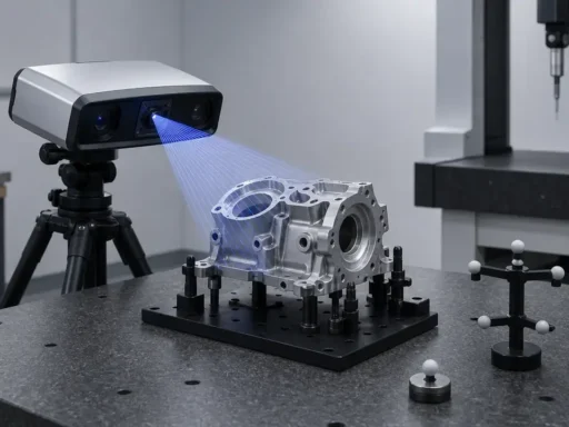
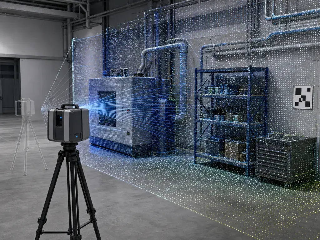
A 3D scanner point cloud starts as sampled surface data, not as a finished model. Depending on the capture route, that sampling may come from laser scans, stereo or time-of-flight depth sensing, or photo-based reconstruction. PCL notes that point clouds can be acquired from hardware sensors such as stereo cameras, 3D scanners, and time-of-flight cameras, while Autodesk’s reality-capture workflow also includes projects built from overlapping photographs. [1] [12]
The dataset usually changes after capture. Scan files may be indexed, aligned, cleaned, merged, clipped, or decimated before they become the version another team receives. Autodesk defines registration as merging scans into one cohesive point cloud, and Autodesk’s project documentation notes that an RCP project references indexed scan data rather than storing the original raw files inside the project file itself. PCL’s VoxelGrid tutorial gives a concrete downsampling example with a 0.01 m leaf size, reducing an example cloud from 460,400 to 41,049 points. [11] [14] [20]
A practical workflow usually looks like this. [1] [11] [20]
- Capture the scene or object as point samples from scans, depth sensing, or photos.
- Register or align multiple scans if the job contains more than one setup.
- Clean the data by removing obvious outliers, moving objects, or irrelevant regions.
- Downsample dense areas when you need smaller files or faster processing.
- Segment or classify parts of the cloud if the workflow needs labels or object groups.
- Export the result in a format that preserves the fields and metadata needed downstream.
- Optionally convert it into a mesh or rebuild it into CAD, BIM, or another model form.
Registration and alignment
In a multi-scan project, registration places separate scans into one cohesive point cloud. Autodesk describes it as specific to scan projects and notes that it can be automatic or manual. The goal is to make all scans share the same spatial frame so they can be compared, merged, and measured together. [11]
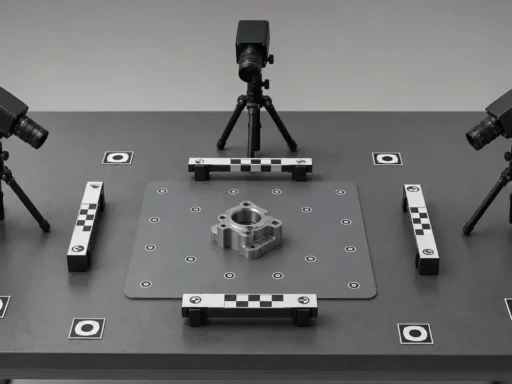
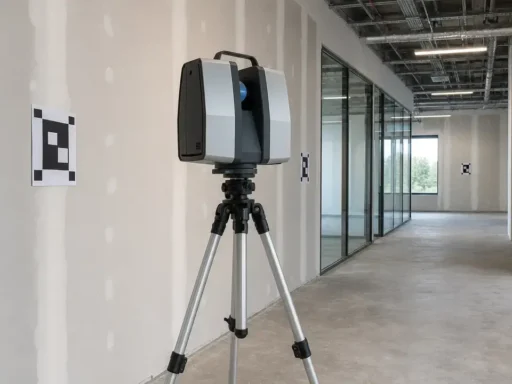
Two common registration paths are target- or control-based registration and cloud-to-cloud registration. Target-based workflows use known reference objects or survey/control points to lock scans together. Cloud-to-cloud methods align overlapping geometry directly. Review literature often describes registration as coarse-to-fine: a rough initial alignment is found first, then refined until the remaining mismatch is smaller. [11] [26]
Photogrammetry uses a related but different idea called stitching. Autodesk treats stitching as specific to photo projects, where images are linked through automatic mesh reconstruction or manual user input rather than through scan registration in the strict terrestrial-scanning sense. A registration residual is the remaining misfit after alignment, so it is a project-level indicator, not the same as an instrument’s single-scan accuracy specification. [11] [26]
Coordinate systems: local vs registered vs georeferenced
XYZ coordinates are meaningless without a coordinate frame and units. In E57-related requirements, physical quantities are represented in SI units, with coordinate and length information in meters and planar angles in radians. Those same requirements note that fixed-position scanners can store data in scanner-local coordinates and specify a transformation to the desired global coordinate system. Autodesk’s E57 export documentation follows the same meters-and-radians convention and can write pose information with the scan record. [16] [22]
After alignment, the cloud may live in a project-registered frame. That means points from different scans now agree with one another inside a shared project coordinate system, even if the project is not tied to any external map projection or survey datum. A registered project frame is coherent for the job, but it is not automatically georeferenced. [11] [22]
Georeferenced point clouds add that external reference layer. In LAS 1.4-R15, coordinate reference system information for the point data is required and is stored in VLRs or EVLRs using GeoTIFF or WKT, depending on point format and encoding. E57 can also carry coordinate-reference information: the Library of Congress format description notes CoordinateMetadata encoded with a WKT string for CRS information. [4] [23]
- Scanner-local: points are stored relative to the instrument or scan setup, commonly with the scanner at the origin in the local frame. [22]
- Project-registered: multiple scans are aligned into one internal project frame. [11]
- Georeferenced CRS: the cloud is tied to an external datum or map projection, with CRS metadata stored through LAS VLRs/EVLRs or E57 coordinate metadata. [4] [23]
File formats and standards
Point cloud formats serve different roles. Some are exchange formats, some are geospatial delivery formats, and some are software-native project containers. Autodesk ReCap lists formats including E57, LAS, RCS/RCP, PTS, PTX, TXT, and XYZ, but support for opening or exporting a format in one application does not guarantee that every attribute survives unchanged in another. [13]
E57 is an exchange format for 3D imaging data. ASTM’s standard summary says an E57 file can store 3D point data, attributes such as color and intensity, and 2D imagery. Public E57 requirements and Autodesk’s export notes also make the unit conventions explicit: coordinates are in meters and planar angles in radians. Autodesk further documents fields such as pose, pointsSize, intensity limits, and color limits, which is a reminder that exporter behavior and field population can vary by software. [2] [16] [22]
LAS is aimed at interoperable lidar and other point cloud records. The OGC LAS page describes it as an open format for common exchange of LiDAR point cloud data, while LAS 1.4-R15 requires CRS information for all point data and places that information in VLRs or EVLRs using GeoTIFF or WKT. LAS itself does not include compression, which the OGC endorsement document states directly. LAZ 1.4 is the separate compressed form, based on LAS 1.4 and LASzip. [3] [4] [5] [6]
| Format | Best at preserving | Often lost | Typical use-case |
|---|---|---|---|
| E57 | 3D points, color, intensity, imagery, scan-level metadata | Exporter-specific project settings or some native organization | Exchange across scan software |
| LAS/LAZ | LiDAR points, common per-point fields, CRS metadata | Nonstandard project metadata or software-specific context | Geospatial delivery and archiving |
| RCS/RCP | Autodesk scan/project context and references | Portability outside the Autodesk ecosystem | Native project workflows |
| PCD | XYZ plus developer-friendly fields such as rgb, normals, and viewpoint | Broader project context and rich interchange metadata | Research, robotics, and processing pipelines |
| PLY | Basic point or polygon geometry, often with simple color | Rich scan metadata and formal CRS handling | Lightweight geometry exchange |
| XYZ/TXT | Bare coordinates and simple extra columns | Most metadata, structure, and CRS detail | Plain-text export and quick interchange |
These format caveats summarize the roles documented by Autodesk, ASTM, LAS/E57 references, and PCL’s PCD documentation rather than promising perfect field retention across all software. [2] [4] [14] [15] [19]
RCS is a single point cloud scan, while RCP is a project file that points to the individual scan files and contains information about them. Autodesk also notes that exporting packaged project information can make shared files quite large, which is one reason native project containers and exchange files play different roles. [14] [15]
For a real job, the key format question is not which one is “best” in the abstract. It is which coordinates, attributes, and metadata the next step actually needs. [2] [3] [14]
Performance metrics
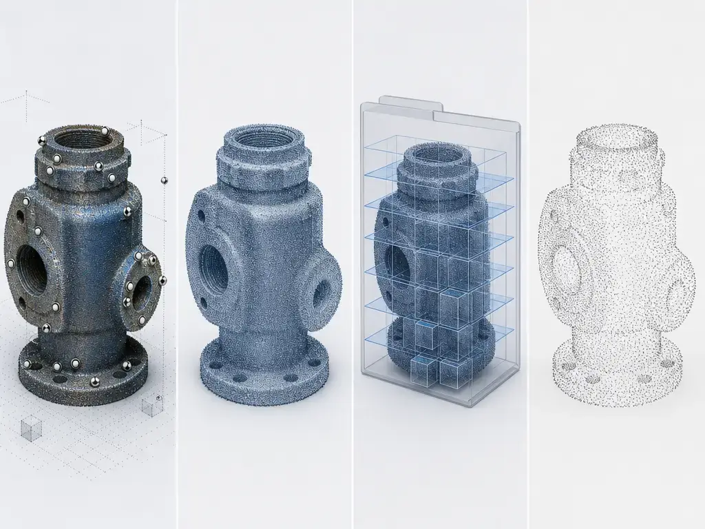
Point density and point spacing are related, but they are not the same thing, and neither one is a synonym for accuracy. Density describes how many points occupy an area, while spacing describes how far apart those samples are. USGS lidar specifications show why exact terminology matters: in the 2025 rev. A tables, Table 1 lists QL2 as aggregate nominal pulse spacing (ANPS) less than or equal to 0.71 m and aggregate nominal pulse density (ANPD) greater than or equal to 2.0 pls/m². In the 2025 rev. A Collection Requirements text, the minimum acceptable quality level for 3DEP is QL2, ANPD shall be no less than 2 points per square meter, and ANPS shall be no greater than 0.70 m. Those values are close, but they are not identical, so the discrepancy should be reported rather than silently normalized. [7] [8]
Metrology terms need the same care. NIST TN 1297 warns that accuracy and precision are qualitative terms that should not be used casually as bare numeric labels, and the NIST/SEMATECH engineering-statistics glossary describes repeatability as short-term variability under controlled conditions while describing accuracy, in metrology context, as total measurement variation including both precision and systematic offset. ISO 10360-13:2021 adds an important testing context: acceptance and reverification tests for optical 3D coordinate measuring systems are tied to measuring lengths stated by the manufacturer and to surface characteristics kept within a cooperative range. For lidar files, intensity is another separate idea altogether: USGS requires intensity values for each multiple discrete return and requires that they be linearly scaled to 16 bits in LAS files per LAS 1.4-R15. [8] [9] [24] [25]
Registration residuals are also easy to misuse. A low residual means the scans fit one another well during alignment. It does not, by itself, prove that the device is accurate everywhere in an absolute sense. Registration error is a project-level alignment result, while scanner specifications describe the instrument under stated test conditions. [11] [26]
| Term | What it is | What it is not |
|---|---|---|
| Accuracy | Closeness to a reference or true value in measurement context | A synonym for density, resolution, or a one-number marketing claim |
| Precision | Agreement or scatter behavior under stated conditions | The same thing as accuracy |
| Repeatability | Short-term variability under the same conditions | Long-term reproducibility or field drift |
| Resolution | A smallest distinguishable change or instrument sensitivity concept | Point spacing, density, or accuracy |
| Point spacing | Distance between neighboring samples | Accuracy |
| Point density | Number of points per area or volume | Proof of measurement quality |
| Noise | Random variation around the sampled surface | Fine detail that should always be preserved |
| Volumetric accuracy | Error behavior across a 3D working volume | A direct substitute for static-lidar point accuracy |
| Registration residual/error | Misfit remaining after alignment | Global truth or full-scene absolute accuracy |
The distinctions in this glossary follow NIST terminology guidance, ISO verification context, and USGS lidar deliverable language. [7] [8] [9] [24] [25]
Device-specific examples below are manufacturer claims, not typical values for all scanners.
| Manufacturer example | Range | Speed | Accuracy note |
|---|---|---|---|
| FARO Focus Premium Max | 0.5–400 m | Up to 2 MPts/sec | 3D accuracy 2 mm @ 10 m and 3.5 mm @ 25 m. [28] |
| Leica RTC360 | 0.5–130 m | Up to 2,000,000 pts/sec | 3D point accuracy 1.9 mm @ 10 m, 2.9 mm @ 20 m, and 5.3 mm @ 40 m. [29] |
| Creaform HandySCAN BLACK Elite | — | — | Accuracy 0.025 mm; volumetric accuracy 0.020 mm + 0.040 mm/m. [30] |
These figures are not interchangeable across device classes. Long-range terrestrial lidar range and point-accuracy specs describe one testing context, while handheld volumetric accuracy describes another. ISO 10360-13 is a useful reminder to read each specification inside its stated measurement conditions rather than mixing them into a single “best accuracy” number. [9]
Processing a point cloud for use
Before a point cloud is useful downstream, it is often cleaned and reshaped for the task. Typical steps include cropping away irrelevant areas, removing moving objects or obvious outliers, and filtering noise so the dataset is easier to inspect, store, and register against other data. Autodesk’s glossary explicitly describes project cleanup as identifying bad points and removing moving objects from a static environment, which is a reminder that “the point cloud” is often already a processed result rather than untouched raw capture. [11]
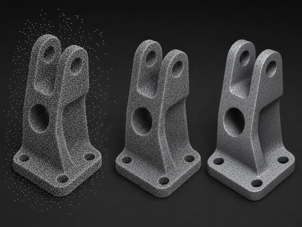
Downsampling and meshing are the next major decisions when lighter data or continuous surfaces are needed. PCL’s VoxelGrid tutorial uses a centroid-per-voxel approach and shows an example with a 0.01 m leaf size, reducing 460,400 points to 41,049 points. That can speed up processing, but it also discards information. For surface reconstruction, Open3D documents alpha shapes, ball pivoting, and Poisson reconstruction, and notes that Poisson may create triangles in low-density areas and extrapolate beyond measured data. A mesh is not just a smaller point cloud; it is a new geometric interpretation of one. [20] [21]
Common processing operations include the following. [1] [20] [21]
- Registration.
- Cropping.
- Outlier removal.
- Voxel downsampling.
- Normal estimation.
- Surface reconstruction.
- Export.
The main tradeoff is straightforward: smaller files and faster workflows usually come with some information loss, and meshing adds inferred geometry instead of merely reorganizing the original samples. [20] [21]
Applications by domain
Point clouds are fit-for-purpose data, not one universal end product. The same captured surface information can support construction documentation, engineering checks, terrain mapping, robotics, or restoration work, but the next step depends on the domain. Autodesk frames reality capture around construction, design, and project documentation uses, while LAS remains an interoperability format for lidar and other point cloud records. [3] [12]
| Domain | Why point clouds help | Typical next step |
|---|---|---|
| Reverse engineering | Capture existing geometry and missing features | Fit surfaces or rebuild CAD geometry |
| Scan-to-BIM / as-built | Record existing conditions for coordination | Compare to plans or model BIM elements |
| Inspection / metrology | Measure deviation, clearance, or form | Compare against tolerances or references |
| Terrain mapping | Represent ground and surface cover at scale | Classify, grid, and deliver lidar/geospatial products |
| Robotics / SLAM | Support localization and obstacle awareness | Fuse scans into navigation maps |
| Cultural heritage | Preserve shape and visible condition | Archive, document, or reconstruct assets |
| 3D printing prep | Provide measured shape reference | Generate a mesh or modeled part before slicing |
The domain mapping above reflects Autodesk’s reality-capture workflow framing and the role of LAS/USGS-style lidar deliverables in terrain mapping. [3] [7] [12]
For terrain mapping, the point cloud is often judged with lidar-specific metrics such as ANPD and ANPS, which belong to the deliverable specification rather than to a general idea of “3D quality.” In construction and design workflows, the cloud is usually reference data for comparison and coordination, not the final fabricated object. [7] [8]
Limitations and common misunderstandings
A point cloud can look dense yet still be inaccurate if calibration, registration, or surface conditions are poor. In metrology-style verification, ISO 10360-13 ties performance checks to manufacturer-stated measuring lengths and to cooperative surface characteristics, so visual fullness is not proof of trustworthy geometry. A low registration residual can still coexist with global offsets or other project problems. [9] [11]
Capture itself has predictable blind spots. Occlusion hides parts of the object or room from any one scanner position, so multiple setups are often required. Reflective, transparent, or otherwise non-cooperative surfaces can also weaken results. In photo-based reconstruction, image overlap and visible features matter, which is one reason photogrammetry projects can need manual refinement or survey-point assistance in difficult areas. [9] [12]
Operational limits show up after capture too. Large files can slow storage, viewing, and downstream processing. Registration drift can accumulate across long projects if alignment control is weak. Meshing also remains an interpretive step: Open3D notes that Poisson reconstruction may create triangles in low-density areas and extrapolate beyond measured data, so a finished surface can include geometry that was never directly sampled. [11] [21]
Research snapshot
Registration research often frames alignment as a coarse-to-fine process: find a workable initial pose, then refine it while analyzing the remaining error. That framing is practical because real point clouds often contain overlap, noise, differing viewpoints, and incomplete coverage, so a single-pass fit is rarely enough. [26]
On the storage side, LAZ remains the standardized compression path for LAS-based workflows. The current OGC LAZ 1.4 community standard states that LAZ 1.4 is based on LAS 1.4 and uses LASzip-derived compression rather than defining a different kind of point cloud altogether. [6]
Why understanding point clouds matters before you scan
The question what is a point cloud matters before you scan because it affects the settings you choose, the deliverable you request, and the mistakes you avoid later. If you understand that a point cloud is sampled surface data rather than an automatic mesh or CAD model, you are less likely to confuse raw capture with editable or printable geometry. That distinction also helps you ask for the right export: E57 when exchange of rich scan data matters, LAS or LAZ when geospatial interoperability and CRS handling matter, and native project formats such as RCP/RCS when the workflow depends on application-specific project context. [1] [2] [3] [11]
FAQ
What is a point cloud?
A point cloud is a set of sampled 3D points, usually stored as X, Y, and Z coordinates, that represents the surface of an object or scene. It may also carry attributes such as color or intensity, but the core idea is still measured points rather than connected faces, edges, or a finished solid model. [1] [11]
Do point clouds have faces or edges?
No. Point clouds do not contain faces or edges. They are collections of individual points. Faces and edges belong to meshes, which add topology on top of geometric positions. That is why a point cloud can work well as measured reference data while still not being a directly editable surface model. [11] [18]
What is a “point cloud model” and is it a real 3D model?
The phrase point cloud model is widely used, but it is loose language. In strict technical terms, a point cloud is data that represents sampled surface points, not automatically a mesh, solid, or parametric CAD model. It becomes one of those only after a reconstruction or modeling step. [1] [11]
Are all point clouds LiDAR data?
No. LiDAR is a common source, but it is not the only one. Point clouds can also come from other 3D scanners, stereo or time-of-flight sensors, and photo-based reconstruction workflows. Autodesk’s reality-capture process also covers projects built from photographs rather than only laser scans. [1] [12]
What is point cloud registration (target-based vs cloud-to-cloud), and what is a registration residual?
Registration is the process of aligning multiple scans into one cohesive point cloud. Target-based registration uses reference targets or control points, while cloud-to-cloud registration fits overlapping geometry directly. A registration residual is the remaining misfit after alignment. It is useful for judging scan-to-scan fit, but it is not the same as absolute measurement accuracy for the whole project. [11] [26]
How do coordinate systems work in point clouds (local vs georeferenced CRS in LAS/E57)?
A point cloud’s XYZ values only make sense if you know the coordinate frame and units. E57 requirements use meters and radians and allow scanner-local coordinates with transforms into a broader frame. LAS 1.4-R15 requires CRS information for all point data and stores it in VLRs or EVLRs using GeoTIFF or WKT. E57 can also carry coordinate metadata using WKT when georeferencing is needed. [4] [22] [23]
Can you 3D print a point cloud? What file do you actually need?
Not directly in most cases. Printers and slicers usually expect a mesh-based file such as STL or 3MF rather than a raw point cloud. Autodesk’s STLOUT documentation describes STL as triangles approximating faces of solids or watertight meshes, and the 3MF Consortium notes that 3MF is recognized as ISO/IEC 25422:2025. So if you start with a point cloud, you typically need meshing or modeling first. [10] [17]
Sources
- PCL About — https://pointclouds.org/about/
- ASTM E2807-11(2019) Standard Specification for 3D Imaging Data Exchange, Version 1.0 — https://store.astm.org/e2807-11r19.html
- OGC LAS Specification standard page — https://www.ogc.org/standards/las/
- ASPRS LAS Specification v1.4-R15 (PDF) — https://www.asprs.org/wp-content/uploads/2019/07/LAS_1_4_r15.pdf
- OGC LAS 1.4 Community Standard PDF — https://docs.ogc.org/cs/17-030r1/17-030r1.pdf
- OGC LAZ 1.4 Community Standard PDF — https://portal.ogc.org/files/?artifact_id=110135&version=2
- USGS Lidar Base Specification: Tables — https://www.usgs.gov/ngp-standards-and-specifications/lidar-base-specification-tables
- USGS Lidar Base Specification: Collection Requirements — https://www.usgs.gov/ngp-standards-and-specifications/lidar-base-specification-collection-requirements
- ISO 10360-13:2021 — https://www.iso.org/standard/74957.html
- 3MF Consortium Specification — https://3mf.io/spec/
- Autodesk ReCap Glossary — https://help.autodesk.com/cloudhelp/ENU/Reality-Capture/files/glossary.html
- Autodesk About the Reality Capture Process — https://help.autodesk.com/cloudhelp/ENU/Reality-Capture/files/Getting_Started/about_reality_capture.html
- Autodesk Supported File Formats — https://help.autodesk.com/cloudhelp/ENU/Reality-Capture/files/Getting_Started/supported_file_formats.html
- Autodesk About Scan and Photogrammetry Files and Projects — https://help.autodesk.com/cloudhelp/ENU/Reality-Capture/files/Getting_Started/Supported_File_Formats/scan_photogrammetry.html
- Autodesk Navisworks ReCap File Reader — https://help.autodesk.com/cloudhelp/2024/ENU/Navisworks/files/GUID-7F1C93E2-66A8-4884-85E1-15B180E0C46F.htm
- Autodesk E57 Export Support – Technical Specification — https://help.autodesk.com/cloudhelp/ENU/Reality-Capture/files/Saving_Exporting_Your_Project/export_e57_technical_specifications.html
- Autodesk AutoCAD STLOUT (Command) — https://help.autodesk.com/cloudhelp/2017/ENU/AutoCAD-Core/files/GUID-5E9946B5-D769-4881-BC0F-21F54840683D.htm
- Autodesk 3ds Max Point Cloud Object — https://help.autodesk.com/cloudhelp/2022/ENU/3DSMax-Modeling/files/GUID-49CE0ACB-1345-4D50-B6E5-361DBFDB5B33.htm
- PCL PCD File Format — https://pointclouds.org/documentation/tutorials/pcd_file_format.html
- PCL VoxelGrid Tutorial — https://pointclouds.org/documentation/tutorials/voxel_grid.html
- Open3D Surface Reconstruction Tutorial — https://www.open3d.org/docs/release/tutorial/geometry/surface_reconstruction.html
- ASTM 3D Image Data Format Requirements — https://e57-3d-imgfmt.sourceforge.net/requirements.html
- Library of Congress E57 Format Description — https://www.loc.gov/preservation/digital/formats/fdd/fdd000563.shtml
- NIST TN 1297 Appendix D1: Terminology — https://www.nist.gov/pml/nist-technical-note-1297/nist-tn-1297-appendix-d1-terminology
- NIST/SEMATECH Engineering Statistics Handbook Glossary — https://www.itl.nist.gov/div898/handbook/glossary.htm
- Registration of Laser Scanning Point Clouds: A Review — https://pmc.ncbi.nlm.nih.gov/articles/PMC5981425/
- FARO Point Clouds for Beginners — https://www.faro.com/en/Resource-Library/Article/Point-Clouds-for-Beginners
- FARO Focus Premium Max brochure (PDF) — https://media.faro.com/-/media/Project/FARO/FARO/FARO/Resources/1_BROCHURE/2024/FARO-Focus/AECO/CMO9773_Brochure_FocusPremiumMax_AECO_ENG_LT_Web_112024.pdf?rev=32d2a3ce59b943828b19a6a2e5374d94
- Leica RTC360 Laser Scanner product page — https://shop.leica-geosystems.com/reality-capture/rtc/leica-rtc360-laser-scanner/buy
- Creaform HandySCAN 3D technical specifications — https://www.creaform3d.com/en/products/portable-3d-scanners/portable-3d-scanner-handyscan-3d/technical-specifications