
Summary
How accurate is photogrammetry? There is no universal number, because accuracy depends on workflow class, capture geometry, image quality, scale or control, calibration, surface behavior, and how the result is validated. [S01] [S11]
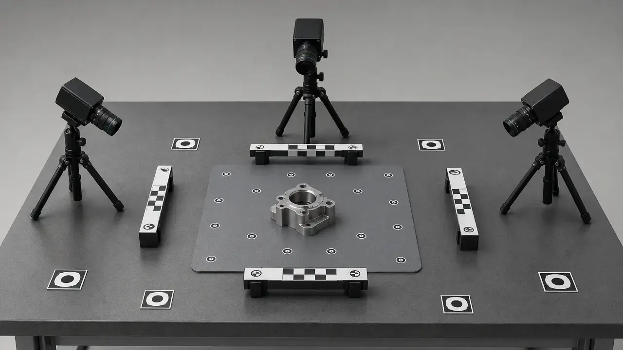
In aerial and drone mapping, a correctly scaled and reconstructed project is often described with guidance around 1–3 × GSD for relative accuracy, but Pix4D also warns that error is not global, so local accuracy can vary across the same model. [S01] Without GCPs, standard GNSS image geolocation can leave final absolute accuracy at the level of a few meters. [S01] With precise georeferencing, typical guidance is about 1–2 × GSD horizontally and 1–3 × GSD vertically. [S01] Controlled close-range work can be far better, but only in engineered setups with strong network design and reference checks: Fraser describes a 26 m radio telescope network that required object-point accuracy of σ = 0.065 mm, while an industrial comparison against CMM ground truth reported mean semisphere-distance errors of 0.040 mm for marker-based photogrammetry, 0.231 mm for one markerless strategy, and 1.721 mm for a weaker strategy affected by focus changes. [S10] [S12]
- Controlled close-range photogrammetry can be sub-millimeter, but only with engineered geometry, reliable scale or targets, and independent reference checks. [S08] [S10] [S12]
- UAV mapping with control can approach GSD-based limits, but the result still depends on overlap, visibility, georeferencing quality, and checkpoints. [S01] [S04]
- Uncontrolled visual modeling may look convincing, yet without external scale, datum control, or independent checks it should be treated as a visual model before a metrology claim. [S09] [S11]
Photogrammetry accuracy at a glance
The safest way to read photogrammetry accuracy is by workflow class, not as one universal number. Most GSD-based rules come from aerial or drone mapping guidance, so they should not be imported as generic rules for tabletop objects, people, or inspection parts. [S01] [S09] [S11]
| Workflow class | Typical accuracy reporting | What mostly limits accuracy | Best validation method |
|---|---|---|---|
| UAV mapping | Relative accuracy around 1–3 × GSD; with precise georeferencing, guidance about 1–2 × GSD in X,Y and 1–3 × GSD in Z. Without GCPs and with standard GNSS, absolute positioning may still be only a few meters. [S01] | GSD, overlap, visibility, image quality, control quality, and georeferencing. Error is not global across the model. [S01] [S03] | Checkpoints for absolute accuracy, with GCPs when external positioning matters. [S04] |
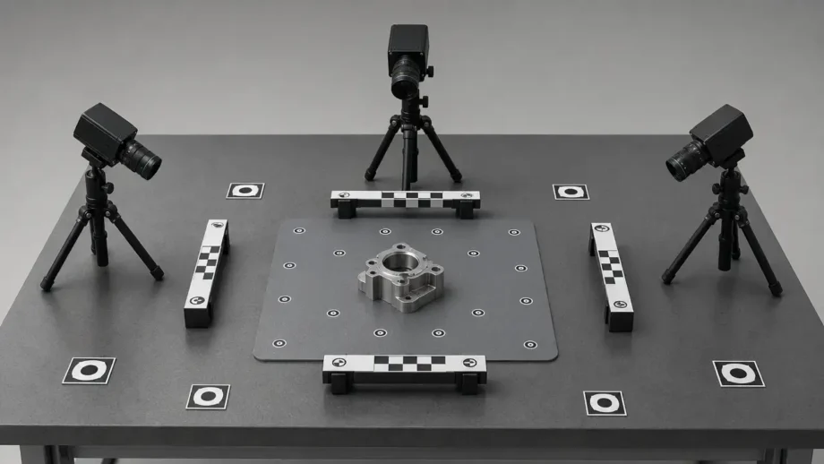
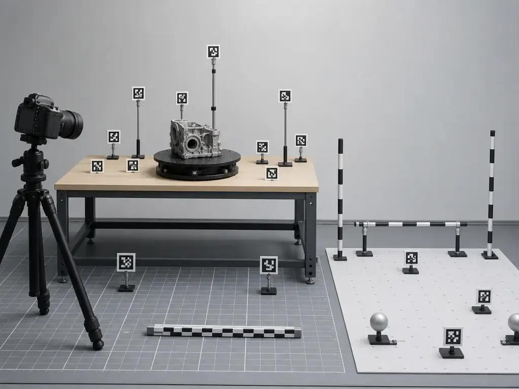
| Object-scale photogrammetry | Scale-bar residuals, check distances, or errors after aligning an image-space model to object space. At least three scale bars are recommended for confidence. [S08] [S09] | Network design, lens distortion, marker quality, and the accuracy of the distance reference itself. [S08] [S10] | Check scale bars or held-out distances, not only the references used to optimize the model. [S08] |
| Controlled close-range inspection | Error against a reference instrument or reference geometry. Published examples range from σ = 0.065 mm in a hyper-redundant network to 0.040 mm mean semisphere-distance error in a marker-based industrial comparison. [S10] [S12] | Capture strategy, scene texture, focus stability, and the quality of the reference comparison. [S10] [S12] | Direct comparison against CMM, laser tracker, or other metrology-grade references. [S12] |
| Multi-camera rigs and hybrid workflows | Project-specific repeatability, check distances, or differences to an external reference rather than a universal mm figure. [S11] [S12] | Rig calibration, subject motion, texture, and how the rig is tied to scale or a reference frame. [S11] | Repeat captures plus independent reference measurements or hybrid comparison against the companion metrology system. [S11] [S12] |
In practice, the validation method matters as much as the number itself. A model can have good internal shape while still being shifted, rotated, or scaled incorrectly in the real world, which is why scale-only references, full datum control, and independent checks need to be kept distinct. [S01] [S08] [S09]
What “accuracy” means in photogrammetry
In photogrammetry, accuracy is not the same as precision, repeatability, or resolution. Accuracy is closeness to the true value. Precision is how tightly repeated measurements agree. Repeatability is how consistent the same workflow is when you run it again. Resolution or point spacing describes how finely a surface is sampled, but that can be finer than the model’s true measurement quality. A dense point cloud can therefore look detailed and still be wrong in scale or position. [S11]
A second distinction is relative versus absolute accuracy. Pix4D defines relative accuracy as how well features agree with each other within the same model or map, and absolute accuracy as the difference between those reconstructed features and their true position in a reference frame. [S01] A model can therefore be internally consistent yet globally wrong: two holes on a part may be spaced correctly relative to each other, while the whole model is shifted, rotated, or scaled away from reality because it was never tied to object space. SfM outputs begin in a relative image-space coordinate system and need alignment to object space, often through a 3D similarity transform based on known control. [S09]
Validation also happens in layers. Internal diagnostics such as reprojection error tell you how well the solved camera model fits the image observations. Constrained residuals tell you how well the solution fits the control data used to build it. Independent checks, such as checkpoints, check scale bars, or external reference measurements, are stronger evidence because they were not used to tune the model. Pix4D describes checkpoints as a way to assess absolute accuracy, while RealityScan’s Ground Test points are specifically withheld from optimization and can reveal deformations such as banana effect. There is still no universally recognized common criterion for formalizing photogrammetry model error across workflows, so the metric needs to be stated with the claim. [S04] [S06] [S11]
Glossary callout
- GSD — Ground sampling distance: the distance between two consecutive pixel centers measured on the ground. It describes image scale, not guaranteed final accuracy. A 5 cm GSD image is 5 cm/pixel, while a 30 cm GSD image is 30 cm/pixel. [S02]
- RMSE — Root mean square error: a summary measure of residual size under a particular test setup or comparison.
- Reprojection error — The pixel-space mismatch between observed image points and the points predicted by the solved camera model.
- Checkpoint — An independently surveyed point used to assess absolute accuracy by comparing known and computed positions. [S04]
- Scale bar — A known distance used to set or check model scale. It does not by itself establish a full external datum. [S08] [S09]
Minimal history — how SfM changed workflows
Classical photogrammetry relied more heavily on pre-measured control and manually planned geometry. Structure from Motion changed that by solving camera pose and scene geometry together from overlapping images, using highly redundant bundle adjustment driven by matched features across multiple views. [S09] That made photogrammetric reconstruction much more accessible, but it did not make scale or orientation automatic. Westoby and colleagues note that SfM point clouds begin in a relative image-space coordinate system and must still be aligned to real-world object space through external references such as GCPs or targets. [S09]
Technical principles — why geometry and calibration control results
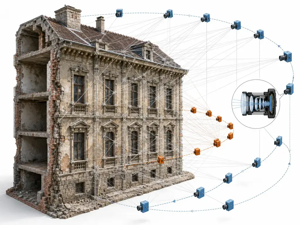
Photogrammetry works by finding tie features across overlapping images and solving cameras and 3D points together in bundle adjustment. Geometry is central to the measurement. If the scene is seen from too few angles, if the baseline is weak, if viewpoints are nearly collinear, or if the surface has repeating patterns, the solver has less information to triangulate reliable positions. Westoby’s SfM overview stresses that the method is best suited to image sets with high overlap that capture full 3D structure from a wide array of positions. [S09] In aerial work, Pix4D recommends at least 75% frontal overlap and 60% side overlap in the general case, with higher overlap for more difficult scenes such as flat agriculture at 80/80, forest and dense vegetation at 85/85, and thermal work at 90/90. [S03] For circular building capture, Pix4D recommends one image every 5–10° and warns against increasing flight height by more than 2× between rounds, because large height jumps change GSD and weaken geometric consistency. [S03]
Calibration matters because the solver is estimating 3D geometry from pixel observations, not from idealized rays. Lens distortion changes where those rays should intersect. Blur reduces the reliability of feature matching. Rolling shutter can distort geometry during motion. Pix4D explicitly warns that rolling-shutter cameras are not recommended for sub-centimeter accuracy results. [S01] RealityScan also notes that even careful human point placement is difficult below 3–4 pixels, a reminder that weak images and weak targets directly turn into weak measurements. [S06]
GSD is best treated as a planning variable. Pix4D defines it as the distance between two consecutive pixel centers measured on the ground, and its examples make the distinction clear: 5 cm GSD means 5 cm per pixel, or 25 cm² per pixel, while 30 cm GSD means 30 cm per pixel, or 900 cm² per pixel. [S02] Those values describe image scale and visible detail, but they are not guarantees of final dimensional accuracy. A low-GSD project with bad geometry can still underperform a higher-GSD project with stronger control and validation. [S01] [S02]
Capture choices that usually improve geometry
- Use strong front and side overlap so the same features are observed from multiple viewpoints. [S03]
- Add convergent views when the subject has depth, facades, or repeating surfaces. [S03] [S09]
- For circular building capture, keep image spacing tight at roughly 5–10° and increase height gradually rather than jumping by more than 2× between rounds. [S03]
- Favor sharp, well-exposed images and stable shutter behavior. [S01] [S05]
- Treat calibration and distortion as measurement issues, not cosmetic cleanup. [S01] [S05]
- Remember that manual marking gets hard below 3–4 pixels, so target visibility and image scale matter. [S06]
- Treat GSD as a planning baseline, not proof that the finished model is accurate. [S02]
Validation and reporting — the metric stack you must not mix up
Internal diagnostics are useful, but they are not the same as field accuracy. Reprojection error tells you how tightly the solved camera model fits the observed image points, and RMSE summarizes residual size under a chosen comparison. Those numbers help diagnose the reconstruction, but they do not by themselves prove that a part, building, or site is correctly sized or correctly located in the real world. [S11]
Constrained residuals sit one step higher. GCP residuals and enabled scale-bar residuals can look very good partly because those references helped define the solution in the first place. Agisoft’s helpdesk makes the distinction explicit: an enabled scale bar is a control used during optimization, while a disabled scale bar is a check used afterward. [S08] The same logic applies to GCPs. If you optimize the model using a reference and then report that same reference as proof of accuracy, you have shown fit to control, not independent accuracy. Pix4D therefore recommends checkpoints for assessing absolute accuracy. [S04]
The strongest claims come from independent test data. RealityScan describes Ground Test points as references that are not involved in optimization and can reveal banana effect if the model is bending while the control still looks good. [S06] In object-scale work, the equivalent is to hold out some scale bars or check distances rather than enabling all of them. In inspection work, the equivalent may be direct comparison against a CMM, laser tracker, or another metrology-grade reference. Because the field still lacks one universally accepted criterion for photogrammetry model quality, the validation method needs to travel with the number being reported. [S08] [S11] [S12]
| Metric | Computed from | What it can tell you | What it cannot prove |
|---|---|---|---|
| Reprojection error | Image observations versus projected model points. | Whether the camera solution fits the image measurements tightly. | Real-world dimensional or positional accuracy by itself. [S11] |
| RMSE | Residuals from a fit or comparison. | Overall error size under the chosen test setup. | Accuracy outside that setup or reference context. [S11] |
| GCP residuals or enabled scale bars | Differences between constrained references and solved values. | How well the model fits the controls used during optimization. | Independent validation, because the same data helped build the solution. [S08] |
| Checkpoints or disabled scale bars | Differences between held-out references and solved values. | Independent evidence for absolute accuracy or scale quality in the tested region. | Accuracy everywhere, unless check coverage is representative. [S04] [S06] [S08] |
Workflow — measurement-ready photogrammetry checklist
A measurement-ready workflow starts by defining the required accuracy before capture. In aerial work that often means choosing a target GSD, planning overlap, and deciding whether the project will rely on onboard geolocation alone, RTK/PPK, GCPs, or some combination. [S01] [S03] [S04] In object-scale work it usually means deciding how scale will be introduced, how targets or features will be distributed through the volume, and what reference will be held out for validation. [S08] [S09] Whatever the workflow, the model’s absolute accuracy cannot exceed the accuracy of its image geolocation or its control references. [S01]
Control and validation should be separated on purpose. Pix4D says checkpoints are used to assess absolute accuracy, not merely to improve the fit. [S04] Agisoft says enabled scale bars are controls and disabled ones are checks. [S08] RealityScan says Ground Test points are withheld from optimization and can expose deformation. [S06] These are all versions of the same rule: do not grade the model with the same references that taught it the answer. [S04] [S06] [S08]
Capture habits matter because they determine how much error the bundle adjustment has to absorb. Pix4D’s overlap guidance and DJI Terra’s visible-light guidance both point toward high redundancy as standard practice, while DJI’s calibration routine adds a concrete capture recipe for one specific use case: 100 m flight altitude, shutter speed of 1/400 s or faster, distortion correction disabled, -45° pitch, and 80% forward with 70% lateral overlap. [S03] [S05] That DJI recipe is not a universal law for all photogrammetry, but it shows how calibration, blur control, and viewpoint planning interact. RealityScan’s note about 3–4 pixel manual marking limits is a reminder that tiny or blurry targets waste potential accuracy even if the rest of the workflow is strong. [S06]
Measurement-ready checklist
- Define the required accuracy before capture, and state whether the claim is relative, absolute, or scale-only. [S01] [S11]
- Choose the workflow class first: UAV mapping, object-scale capture, multi-camera rig, or hybrid inspection. [S11]
- For general aerial mapping, plan at least 75% frontal overlap and 60% side overlap, increasing for difficult scenes. [S03]
- For DJI Terra visible-light missions, 80% forward and 70% side overlap are recommended, with 65% forward and 60% side as a lower reduction minimum. [S05]
- If you need GCP control, use at least 3 points and preferably 5–10 distributed across the project. [S04]
- Size AutoGCP targets to at least 20× the project’s average GSD. [S04]
- For circular building capture, do not rely on one ring alone; use multiple heights and keep the height change between rounds below 2×. [S03]
- In object-scale work, use at least three scale bars when that workflow is appropriate. [S08]
- Keep control and check references separate: enabled scale bars are controls, disabled ones are checks. [S08]
- Set the scale-bar accuracy field to the real accuracy of the distance-measurement device; Agisoft’s default example value is 0.001 m, not a universal truth. [S08]
- Use checkpoints or Ground Test points for validation rather than optimization. [S04] [S06]
- Avoid rolling-shutter capture for sub-centimeter claims unless you have specifically tested the workflow. [S01]
- Keep images sharp and blur low; DJI’s calibration guidance includes shutter speed of 1/400 s or faster and distortion correction disabled in that specific routine. [S05]
- Distribute targets, checks, and references across the full scene volume so local bending is easier to detect. [S06] [S09]
For aerial jobs, the practical sequence is usually: choose GSD, design overlap, place control, then verify with checkpoints. For object-scale jobs, it is more often: design viewpoint coverage, place scale or targets, reserve some checks, then compare against held-out distances or another reference. In both cases, the workflow becomes trustworthy when the validation remains independent of the optimization. [S02] [S04] [S08]
Workflow classes and typical expectations
The main workflow classes are close-range object photogrammetry, UAV or aerial mapping, multi-camera rigs for people or dynamic capture, and hybrid metrology workflows that combine photogrammetry with another reference system. They are not interchangeable. Aerial mapping often reports accuracy in GSD-based terms because the project is tied to ground scale and georeferencing. Close-range object work more often reports scale-bar checks or differences to a reference instrument. Multi-camera rigs often care about repeatability, consistency, and how well the rig is tied to scale rather than about one universal mm figure. Hybrid metrology workflows inherit both the strengths and the constraints of the reference instrument they are paired with. [S01] [S08] [S11] [S12]
This is why cross-applying rules is misleading. Pix4D’s 1–3 × GSD guidance is useful for aerial or drone mapping when the project is correctly reconstructed and scaled, but it is not a generic tabletop rule. [S01] Object-scale scale bars can establish or check scale, yet they do not create a full external datum on their own. [S08] SfM models start in image space and must be aligned to object space before scale and orientation become meaningful. [S09] In engineered close-range networks, redundancy can be very high, with Fraser noting 10–20 images per station or more, but the final result still depends on the specific design and reference used. [S10]
| Workflow type | Best use | Typical reporting metric | Best validation method |
|---|---|---|---|
| Close-range objects | Parts, artifacts, props, and small scenes where viewpoint geometry can be tightly controlled. | Scale-bar residuals, held-out distances, or comparison to a reference model. [S08] [S09] | Check scale bars, held-out distances, or direct comparison to another instrument. [S08] |
| UAV / aerial mapping | Terrain, sites, roofs, stockpiles, orthomosaics, DSMs, and larger structures. | Relative accuracy around 1–3 × GSD; with precise georeferencing, about 1–2 × GSD in X,Y and 1–3 × GSD in Z. Without control, absolute position may still be only a few meters. [S01] | GCPs plus checkpoints, or precise onboard georeferencing plus checkpoints. [S01] [S04] |
| Multi-camera rigs | People, bodies, repeated production capture, or motion-limited scenes. | Project-specific repeatability, scale checks, and reference comparisons rather than a universal GSD rule. [S11] | Repeat captures with independent scale or reference objects. [S11] |
| Hybrid metrology | Inspection workflows that merge photogrammetry with laser tracker, CMM, or scanner data. | Difference to the reference instrument or residuals in a merged coordinate system. [S12] | Direct comparison against the companion metrology system. [S12] |
Photogrammetry accuracy vs laser scanning
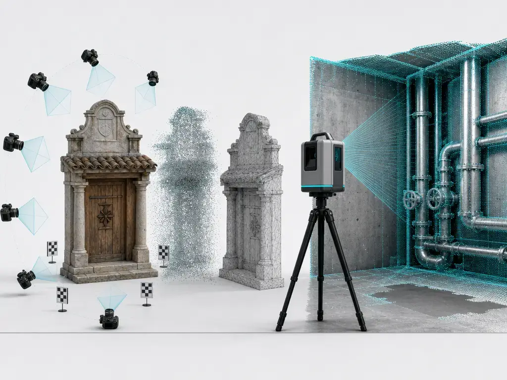
The phrase photogrammetry accuracy vs laser scanning often hides an apples-to-oranges comparison. Photogrammetry usually produces a project-level outcome whose accuracy depends on geometry, image scale, control, calibration, and validation. [S01] Scanner vendors, by contrast, often publish device-level specifications such as point accuracy, volumetric accuracy, resolution, range, or measurement rate, sometimes under defined standards or acceptance tests. [S14] [S15] [S17] [S18] ASTM E2938, for example, is a relative-range test method for medium-range 3D imaging systems that operate over at least part of the 2 to 150 m range. [S14] ISO 10360-13 is an acceptance and reverification standard for optical 3D coordinate measuring systems, but its scope is restricted to cooperative surface conditions. [S15] Those are useful frameworks, yet they are not the same as saying a photogrammetry project will always be accurate to one device-spec number. [S01] [S15]
Photogrammetry competes well when the subject has enough texture, the capture geometry is strong, and the model is validated against appropriate checks. It is often attractive for large objects, mixed environments, heritage recording, and situations where color and surface context matter alongside shape. [S01] [S09] Scanner classes tend to win when surfaces are cooperative, illumination is controlled, and the job demands a device specification that maps cleanly onto a known test method. A Creaform HandySCAN BLACK Elite page, for instance, separates 0.025 mm accuracy, 0.020 mm + 0.040 mm/m volumetric accuracy, 0.025 mm resolution, and 1,300,000 measurements/s, with acceptance testing based on VDI/VDE 2634 part 3. [S17] FARO’s Focus line uses a different style again, advertising model-dependent range and “up to” 2 mm 3D accuracy, such as 200 m for Focus Premium and 400 m for Focus Premium Max. [S18]
| Method | What it measures | How accuracy is usually specified | Common error sources |
|---|---|---|---|
| Photogrammetry | Surface shape and scene geometry reconstructed from overlapping images. | Project outcome: often GSD-based guidance in aerial work, or residuals against scale bars, checkpoints, and reference models. [S01] [S08] | Weak geometry, low texture, blur, lens distortion, poor control, and local variations in error. [S01] [S09] |
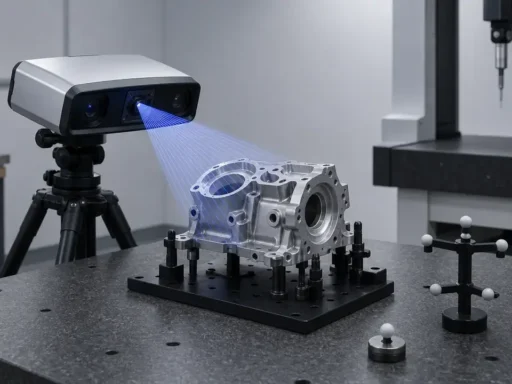
| Handheld triangulation / structured light | Small-to-medium parts in close range. | Vendor specs such as accuracy, volumetric accuracy, resolution, and measurement rate. [S17] | Reflective surfaces, occlusion, working-distance effects, and operator technique. [S15] [S17] |
| Structured-light / optical metrology scanners | Controlled close-range measurement on cooperative surfaces. | Acceptance or reverification tests under standards such as ISO 10360-13. [S15] | Surface condition, calibration state, and environmental stability. [S15] |
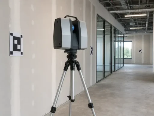
| Terrestrial LiDAR | Room-, building-, or site-scale point clouds. | Vendor range and 3D accuracy claims, often phrased as “up to” values. [S18] | Range, reflectivity, incidence angle, registration, and occlusion. [S14] [S18] |
The practical comparison is not “Which label is smaller?” but “Which workflow can honestly meet the requirement and prove it?” A project RMSE from photogrammetry is not the same as a scanner’s volumetric-accuracy spec, and a scanner’s “up to” accuracy figure is not a promise that every field setup will match that best-case condition. [S11] [S17] [S18]
Standards and traceability context
Standards matter because measurement claims are stronger when they point to a known test method instead of vague marketing language. In geospatial work, the standard is often about how positional accuracy should be reported and checked across a mapped product. In device-based metrology, the standard is more often about how a particular class of instrument is accepted or reverifed under defined conditions. These are related ideas, but they are not interchangeable. [S13] [S14] [S15]
The 2024 ASPRS update is a good example of a reporting framework rather than a single device test. ASPRS says Edition 2 Version 2 increased the minimum number of checkpoints for product-accuracy assessment from 20 to 30, set a maximum of 120, introduced the term “three-dimensional positional accuracy,” and removed the 95% confidence level as an accuracy measure. [S13] ASTM E2938, by contrast, is about relative-range performance of medium-range 3D imaging systems operating over at least part of 2 to 150 m. [S14] ISO 10360-13 is about optical 3D CMS acceptance and reverification under cooperative surface conditions. [S15] ISO 17123-8 sits on the control-measurement side: it specifies field procedures for evaluating the precision, or repeatability, of GNSS RTK systems used in surveying and related measurement work. [S16]
Standards explainer
- ASPRS — A positional-accuracy reporting framework for geospatial products. The 2024 update raised the minimum checkpoint count from 20 to 30, capped maximum checkpoints at 120, introduced “three-dimensional positional accuracy,” and removed the 95% confidence level as an accuracy measure. [S13]
- ASTM E2938 — A relative-range test method for medium-range 3D imaging systems, covering systems that operate within at least part of the 2 to 150 m range. [S14]
- ISO 10360-13 — An acceptance and reverification standard for optical 3D coordinate measuring systems, applicable under cooperative surface conditions. [S15]
Applications — when photogrammetry is accurate enough
Photogrammetry is accurate enough when the measurement claim matches the workflow and the validation method. That makes it a practical option for many 3D printing references, heritage documentation, site and stockpile work, and drone mapping projects, especially when the result is checked against scale bars, checkpoints, or another reference. [S01] [S04] [S08] In aerial work, strong georeferencing can bring results toward GSD-based expectations, while standard-GNSS, no-GCP projects can still remain only a few meters in absolute position. [S01] In object-scale work, scale bars are useful and at least three are recommended, but they must be handled as either controls or checks, and they establish scale rather than a full external datum by themselves. [S08] The closer a job moves toward tight inspection, the more the burden shifts from “Does the model look right?” to “Can the workflow prove the number?” [S11]
Good fit
- Heritage recording where color, shape, and context matter and key dimensions can be checked. [S08] [S09]
- Drone mapping with GCPs or precise georeferencing plus checkpoints. [S01] [S04]
- Stockpile, terrain, and site documentation where relative geometry matters more than tight metrology. [S01]
- 3D printing references, props, and visual assets where scale can be checked and the model does not need a formal metrology claim. [S08]
Use caution
- Human bodies and faces, where motion, pose change, hair, and soft tissue complicate repeatable measurement.
- Mixed surfaces with glare, transparency, low texture, or repeated patterns. [S01] [S09]
- Any project missing checkpoints, check distances, or other independent validation. [S04] [S06]
Prefer laser, structured-light, or CMM
- Tight dimensional inspection on cooperative surfaces. [S12] [S15]
- Jobs that need device-spec traceability under a defined test framework. [S15] [S17]
- Cases where proving uncertainty with photogrammetry would be harder than measuring directly with the reference instrument. [S11] [S12]
Limitations and common photogrammetry error sources
Many limits come from the scene itself. Low texture, repeated patterns, shiny finishes, transparency, deep shadows, and unstable subjects all make feature matching and triangulation less reliable. Westoby notes that image texture and resolution are major determinants of output quality, while Pix4D notes that sharp edges, trees, reflective surfaces, and some roads or rooftops can be locally less accurate. [S01] [S09]
Geometry and control problems are just as important, and this is where a lot of real photogrammetry error comes from. If overlap falls below recommended levels, the model may still reconstruct but the geometry becomes less stable. Pix4D’s general mapping guidance starts at 75% frontal and 60% side overlap, with higher values for more difficult scenes. [S03] Weak viewing angles, long thin capture paths, sparse target distribution, and poor scale layout all make it easier for the solution to drift. RealityScan warns that human clicking is difficult below 3–4 pixels and that Ground Test points can expose banana effect when the optimized model looks better than it really is. [S06] Pix4D also warns that local error is not global, so one part of a model may be much better or worse than another, and rolling-shutter cameras are specifically not recommended for sub-centimeter accuracy results. [S01]
Post-processing can hide defects without fixing them. Smoothing, hole filling, and mesh cleanup may make a model easier to view, but they do not restore missing geometric evidence from weak images or weak geometry. If the original capture was underconstrained, the cleaned mesh can simply look more confident than the measurements actually support. [S11]
Common failure modes
- Low texture or repeated texture. [S09]
- Specular reflections on shiny surfaces. [S01]
- Transparency or translucency.
- Motion blur. [S01] [S05]
- Rolling-shutter distortion in motion-sensitive work. [S01]
- Poor focus or exposure. [S05]
- Insufficient overlap for the scene type. [S03]
- Weak convergence angles or long thin camera networks. [S09] [S10]
- Sparse or uneven control distribution. [S04] [S09]
- Scale drift from too few or poorly placed scale references. [S08]
- Manual marking error below about 3–4 pixels. [S06]
- Over-trusting a cleaned mesh without independent checks. [S11]
Bottom line: how accurate is photogrammetry?
There is no single number that transfers cleanly across drone mapping, object capture, people scanning, and inspection. So, how accurate is photogrammetry? In aerial work, the same method can range from roughly 1–3 × GSD relative accuracy in a correctly reconstructed project to only a few meters of absolute accuracy when standard GNSS is used without GCPs, while precisely georeferenced projects can approach about 1–2 × GSD in X,Y and 1–3 × GSD in Z. [S01] In object-scale work, scale bars improve trust only when the reference itself is accurate, at least three are used where appropriate, and some references are kept as checks rather than controls. [S08] Across all workflows, the defensible answer comes from geometry, calibration, surface behavior, and independent validation, not from a universal headline figure. [S11]
FAQ
Is photogrammetry accurate enough for 3D printing?
Usually yes, if the object is captured at suitable image scale and the model is checked for scale. For object-scale work, Agisoft recommends at least three scale bars for better confidence, and some of those references should be left as checks when measurement matters. [S08] What matters for printing is usually consistent shape and scale, not a formal metrology claim.
What’s the difference between photogrammetry accuracy and precision?
Accuracy is closeness to the true value. Precision is how tightly repeated measurements agree with each other. A workflow can be precise but still inaccurate if scale, control, or calibration are biased. Pix4D’s distinction between relative and absolute accuracy is useful here, because a model can be internally consistent while still be wrong in real-world position. [S01]
Why isn’t reprojection error the same as dimensional accuracy?
Reprojection error is an internal image-fit metric. It tells you how well the solved cameras explain the clicked or matched image points, not whether the object is the correct size in the real world. Independent references such as checkpoints, check scale bars, or Ground Test points are stronger because they were not used to optimize the solution. [S04] [S06] [S11]
How do scale bars differ from GCPs and checkpoints?
Scale bars set or check a known distance, which helps with model scale. GCPs place the model in an external reference frame, adding position and orientation as well as scale. Checkpoints are surveyed references kept out of optimization so they can test absolute accuracy afterward. Agisoft also distinguishes enabled control scale bars from disabled check scale bars. [S04] [S08] [S09]
How should you compare project RMSE to a scanner’s volumetric accuracy spec?
Do not treat them as the same kind of number. Project RMSE is a workflow result under a specific capture and validation setup. A scanner’s volumetric-accuracy spec is a device specification under defined conditions. For example, Creaform separates 0.025 mm accuracy from 0.020 mm + 0.040 mm/m volumetric accuracy on the HandySCAN BLACK Elite page, while FARO uses “up to” 2 mm 3D accuracy language on Focus pages. [S17] [S18]
What overlap do you actually need?
For general aerial mapping, Pix4D recommends at least 75% frontal overlap and 60% side overlap, with higher values for tougher scenes such as 80/80 for flat agriculture, 85/85 for forest, and 90/90 for thermal work. [S03] DJI Terra’s visible-light guidance is 80% forward and 70% side, with 65% and 60% as a lower reduction minimum. [S05]
What causes the biggest photogrammetry errors in real scenes?
The biggest causes are usually weak geometry, weak texture, blur, distortion, reflective or transparent surfaces, and weak control. RealityScan also warns that manual point placement becomes difficult below 3–4 pixels, while Pix4D warns that rolling-shutter cameras are not recommended for sub-centimeter accuracy results and that local error is not uniform across a model. [S01] [S06]
Sources
- S01. Pix4D Relative vs Absolute Accuracy. Official documentation, Copyright 2026. https://support.pix4d.com/hc/en-us/articles/202558889
- S02. Ground sampling distance (GSD) in photogrammetry. Official documentation, Copyright 2026. https://support.pix4d.com/hc/en-us/articles/202559809
- S03. Image acquisition – PIX4Dmapper. Official documentation, Copyright 2026. https://support.pix4d.com/hc/en-us/articles/115002471546
- S04. Tie points in photogrammetry project (GCPs, CPs, MTPs, and ATPs) – PIX4Dmapper. Official documentation, Copyright 2026. https://support.pix4d.com/hc/en-us/articles/115000140963
- S05. DJI Terra – FAQ. Manufacturer documentation, page live 2026. https://enterprise.dji.com/dji-terra/faq
- S06. Control Points – RealityScan Help. Official documentation, current 2026. https://rshelp.capturingreality.com/en-US/tools/controlpoints.htm
- S07. Agisoft Metashape User Manual – Professional Edition, Version 2.3. Official documentation, 2026. https://www.agisoft.com/pdf/metashape-pro_2_3_en.pdf
- S08. Creating scale bars in the project without coded targets. Manufacturer help article, modified 2026-03-25. https://agisoft.freshdesk.com/support/solutions/articles/31000162602-creating-scale-bars-in-the-project-without-coded-targets
- S09. Westoby et al. (2012), “Structure-from-Motion” photogrammetry: a low-cost, effective tool for geoscience applications. Scientific source, 2012. https://researchportal.northumbria.ac.uk/ws/portalfiles/portal/65822314/Westoby_et_al._GEOMORPH_2012_Accepted.pdf
- S10. Fraser (2005), Hyper Redundancy for Accuracy Enhancement in Automated Close Range Photogrammetry. Scientific source, 2005. https://onlinelibrary.wiley.com/doi/10.1111/j.1477-9730.2005.00327.x
- S11. di Filippo et al. (2023), Methodologies for assessing the quality of 3D models obtained using close-range photogrammetry. Scientific source, published 2023-07-08. https://link.springer.com/article/10.1007/s12008-023-01428-z
- S12. Prieto et al. (2024), Markerless photogrammetry in industrial inspection. Scientific source, 2024-12-13. https://isprs-archives.copernicus.org/articles/XLVIII-2-W7-2024/121/2024/isprs-archives-XLVIII-2-W7-2024-121-2024.pdf
- S13. ASPRS Approves Edition 2, Version 2 of the ASPRS Positional Accuracy Standards for Digital Geospatial Data (2024). Industry society announcement, 2024-06-28. https://old.asprs.org/archives/asprs-approves-edition-2-version-2-of-the-asprs-positional-accuracy-standards-for-digital-geospatial-data-2024.html
- S14. ASTM E2938-15(2023), Standard Test Method for Evaluating the Relative-Range Measurement Performance of 3D Imaging Systems in the Medium Range. Standard page, updated 2024-01-01. https://store.astm.org/e2938-15r23.html
- S15. ISO 10360-13:2021, Geometrical product specifications (GPS) — Acceptance and reverification tests for coordinate measuring systems (CMS) — Part 13: Optical 3D CMS. Standard page, 2021-09. https://www.iso.org/standard/74957.html
- S16. ISO 17123-8:2015, Optics and optical instruments — Field procedures for testing geodetic and surveying instruments — Part 8: GNSS field measurement systems in real-time kinematic (RTK). Standard page, 2015-06, confirmed 2025. https://www.iso.org/standard/62961.html
- S17. HandySCAN 3D BLACK Series Technical Specifications. Manufacturer specifications, current 2026. https://www.creaform3d.com/en/products/portable-3d-scanners/portable-3d-scanner-handyscan-3d/technical-specifications
- S18. FARO Focus Laser Scanning Solution. Manufacturer specifications, current 2026. https://www.faro.com/en/Products/Hardware/Focus-Laser-Scanners